The Domain Name System (DNS) [DNS] is a fa- ... able to reach a mobile user, the directory service allows a user to register to receive calls at a par-.
Architecture for Signaling, Directory Services and Transport for Packet Telephony N. Anerousis, R. Gopalakrishnan, C.R. Kalmanek, A.E. Kaplan, W.T. Marshall, P.P. Mishra, P.Z. Onufryk, K.K. Ramakrishnan, C.J. Sreenan AT&T Labs - Research Florham Park, NJ 07932
Abstract It is likely that telephony, and multimedia communications generally, will be carried largely on packet networks in the future. We consider this to be an opportunity to rethink the way such services are provided. In particular, our architecture provides the following. First, a flexible directory service that allows both terminal and user mobility. The directory service also supports user-specified control of the user location function. Names in this directory structure are not restricted to traditional telephone numbers, but may be any fully qualified distinguishing name, that is, any way of uniquely identifying a user. Second, an application layer signaling system that allows negotiated setup of calls that include multimedia calls using various signal encodings. Third, a voice encapsulation format that is simple and efficient. In addition, the packet network must interact with the current public switched telephone network (PSTN) for voice-grade services. To the extent that the underlying packet networks are capable of providing adequate service with respect to bandwidth, delay and loss, the service model is essentially independent of the underlying packet transport.
1. Introduction Packet telephony is of increasing interest in both the telecommunications and Internet communities. With the ability to integrate data with voice both in the network and at the terminal, there can be increased flexibility in handling voice communication as well as the opportunity to offer a variety of creative new services. In fact, this is likely to be true not just for voice, but also for a variety of real-time multimedia streams. This paper describes an overall architecture for packet telephony that allows for more flexible communication, while also allowing for the ability to integrate multiple real-time streams. There are a large number of efforts currently underway to architect various pieces of a packet telephony service. However, these are currently being put together as several pieces, each addressing an individual protocol need. Furthermore, they are being developed by more than one body, such as in the Internet Engineering Task Force (IETF), ATM Forum, Voice over IP and other consortia. Our goal is to develop an overall protocol architecture that is both capable of supporting multimedia streams while exploiting efficiencies by recognizing the unique needs of telephony. We address the problems of providing a powerful directory service, flexible end-to-end signaling and efficient transport of voice. One of the lessons we learn from packet networks is the flexibility and power of the services that can be created by involving both the network components as well as the end-sys-
tems. At the same time, it is important to support terminals that are extremely low cost that may have little or no intelligence, such as the simple telephone devices many of us use. While packet networks have taught us the benefits of flexibility, they have also shown us the need for quality of service in the network to support quality telephony. Our architecture is agnostic towards the underlying network and datalink architectures. However, it is clear that the promise of ATM to provide stringent quality of service support, including good control over delay, is highly desirable. In networks which use virtual circuits, our architecture takes advantage of the state maintained in the network. Flexible directory services make it much more convenient to reach a user. We need no longer to be constrained to reaching a user at a single attachment point, specified by a single phone number. A packet telephony service already requires a directory service function which can translate between telephone numbers and network layer addresses, such as IP or ATM addresses. We enhance this low-level service to allow one to reach a person using a “name”, rather than a number. Thus, user mobility is supported as a fundamental capability of our architecture. Since the directory server returns information about a user, we need to provide the user with the ability to control and customize such access. The directory service allows for the incorporation of profiles for how a name resolution query is handled, and provides the calling user with a flexible set of call appearances and options. Some of these features are already present in the current telephone network with “personal phone numbers” and intelligent 800-number services. However, our approach promises to be more flexible while also giving more control to the user. Terminal mobility is handled by interfacing the directory service to the underlying network functions that deal with mobility, thus isolating the user from its complexities. Traditional telephone signaling assumes relatively simple customer premises equipment (CPE). As a result, the functions of establishing connectivity, performing call management, controlling CPE, and providing advanced features are all integrated under the umbrella of a single protocol architecture. As a result of this monolithic design, it is complex and inflexible. Packet networks already provide signaling that is meant to establish connectivity efficiently. We therefore view the remaining pieces of signaling as application-layer functions, that can tailor the communication between the participating applications appropriately. This has the advantage of allowing application-layer signaling (ALS) to evolve to support a wide-range of functions, including the support of multiple media, independent of the underlying network architecture. Our ALS architecture is used to exchange capabilities and manage session state between packet telephony applications. It uses logical channels as pipes for communicating both control and media data, so as to abstract the details of the underlying transport. Logical channels can be used to multiplex control and media channels into a single shared context at the transport layer. The capabilities negotiation function in ALS allows for flexibility: there is no need to ensure that only predefined media channels and encodings be used. The third element of our design is a protocol for audio encapsulation. Our emphasis is to develop a simple encoding with only the essential overhead needed for transport of audio data, while also allowing for synchronization among multiple media streams. Therefore, our protocol eliminates some of the fields in the RTP protocol [RTP] that are not needed for basic voice transport. We allow the use of header extensions to add other end-to-end information, such as timestamps, as needed.
A gateway supports interoperation with the circuit-switched telephone network. The gateway acts as an endpoint for our ALS protocol and interworks with traditional telephony signaling. There are several ongoing efforts that are related to the work that we outline in this paper. The CMA effort in the Voice over IP consortium [CMA] promises to provide some of the functions that we provide in the directory service. However, it does not address user mobility explicitly, and it requires the client to query a particular server to reach a given user. We also deal with user “personas” and terminal mobility in more detail. The IETF’s draft Session Initiation Protocol [SIP] addresses some of the functionality of our ALS architecture. SIP is used to invite a user to join a call. Invitations use email addresses, with an optional level of indirection provided by a proxy at the remote end which forwards the request to the user’s current IP address. SIP adopts a minimalist approach which results in a separate message exchange for terminal capability exchange and the need for entirely separate protocols for call control, e.g. to add/drop new media streams or terminate a call. We believe that judicious integration of session control with session invitation and capability negotiation, as in our ALS protocol, provides a more efficient solution. H.323 is an ITU standard [H323] for multimedia conferencing. The emphasis is on establishing connectivity between terminal devices within an organization’s LAN. Integration with a directory service is not addressed. H.323 addresses a large number of goals and seeks to be very flexible, making it complex and sometimes inefficient. Section 2 discusses the directory service. Section 3 focuses on application-layer signaling. Section 4 describes our approach to end-to-end transport of control and real-time data. Section 5 gives an example of registration and call setup. Section 6 discusses interworking with the existing circuitswitched telephone network and the status of our implementation efforts. Section 7 provides a summary.
2. Directory Service Name and directory services traditionally provide the capability to store and retrieve information about users, terminal devices or other services. The Domain Name System (DNS) [DNS] is a familiar example of a directory service which provides resolution of Internet domain names to Internet addresses. Directory services are useful because they allow people to use a “name” to initiate communication, rather than an “address,” since addresses are typically difficult to remember and use. A directory service is used to provide a resolution of the “name” that is supplied by the user to an address used in the network. As a result, the directory service isolates the details of network addressing and network topology from the user. Our directory service significantly enhances this traditional name resolution function by providing support for reaching a person, rather than simply resolving a name to the address of a particular terminal. In general, a user may be reachable in a number of ways, for example, by telephone, fax or pager. Moreover, we can generalize the notion of “reaching” someone to include reaching a “proxy” or service that the user has specified. Since a user can be reached in a number of ways and at a number of different addresses, our directory service resolves a name to one or more call appearances. A call appearance is a data structure that describes one way of reaching a user. For example, the call appearance for a packet telephone contains its address and an indication that it is capable of handling voice.
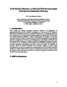
Our directory service also supports user mobility as a fundamental part of its design. In order to be able to reach a mobile user, the directory service allows a user to register to receive calls at a particular terminal if she wishes to be reached there. Registration creates a new call appearance for the user in the directory service. Name resolution can then return this call appearance, along with an indication that it represents the user’s current location. Deregistration can be based on a timeout, explicit deregistration, or implicit deregistration when a user registers to receive calls at another terminal, depending on the user profile and information provided in the registration request. User-specified profiles allow flexibility and customization in the directory service. Name resolution queries are processed by a query-handling profile (QHP), which contains the logic for handling a query related to a particular user. Depending on the user’s preferences, the directory service filters the call appearances indicating where a user can be reached based on who sent the query, the timeof-day, and the purpose of call. In addition, a query can contain a persona for the name being resolved, and a user can specify a different query-handling profile for each of his personas. This allows separate query-handling logic to be used for a user’s work, home and other personas. In addition to providing customization, the query-handling profile allows the user greater control over the privacy of information than a traditional directory service. The directory service is designed to enable the evolution to multimedia communications. It is very convenient to store some minimal information about a terminal’s capabilities in its call appearance record, and to indicate the desired media type(s) for the call in the query. This allows the directory service to filter the information that is returned so that it includes only those endpoints that support the desired media types. This section focuses primarily on the service interface provided by the directory service, rather than the implementation. The service interface is location-independent: a user accesses the service, rather a particular server. However, in order for the directory service to scale to a large number of users, we expect that it will need to be distributed. Like DNS and X.500, the name space can be organized hierarchically and the directory database can be partitioned according to the hierarchical structure of the name space. Reliability and load balancing can be achieved by having multiple replicas of partitions of the database. Caching of the results of directory lookups may also be used. 2.1 Contents of the Directory Service Figure 1 illustrates the contents of a user record in a directory server. Each user is identified by a unique distinguishing name (DN), that is used to locate the record associated with the user. The record contains information about the user (e.g. full name, address, etc.), credentials used for authenticating changes to the user record and for location registration, and a number of query-handling profiles associated with different user personas. In addition, the user record contains a number of call appearances associated with different ways the user can be reached. Call appearances are typically associated with a particular terminal device or server. Each call appearance contains information related to that device, including the terminal’s network layer address (NLA) and the transport layer address (TLA) of the application listening for incoming calls. The call appearance typically also contains a minimal description of the terminal capabilities, such as audio, video, or fax, as well as descriptive information, such as “voice mail server” or “home phone” that can be used by the application that initiated the query. In order to support terminal mobility, we include a unique electronic serial number (ESN) for each terminal.
Directory User Record DN User info
Caller
Query
Credentials QHP1 QHP2
Response (CHP)
Call Appearance Records ESN NLA
TLA
Termcap
Descr
ESN NLA
TLA
Termcap
Descr
ESN NLA
TLA
Termcap
Descr
NLA
TLA
Termcap
Descr
DN
optional optional
optional
Figure 1: The Directory
Another type of call appearance contains the DN of another user, for example, a secretary. In this case, the call appearance could contain the NLA and TLA of the secretary’s terminal, avoiding the need to place a second query to the directory service to retrieve this information. However, storing the NLA and TLA here does not support mobility for the alternate user. If such mobility is important, we might prefer to pay the expense of another query. The response to a query is a call handling profile (CHP). A CHP consists of a set of call appearances, each of which contains the network layer address of an endpoint associated with the user. The call handling profile indicates the user’s preferences for how the caller should reach him. A priority field indicates the user’s preference for the order in which call appearances are attempted. Thus, after hours, a user may prefer callers to leave a voice mail message, but may also return a home phone number to be used in case of emergencies. Entries with the same priority are attempted in an arbitrary order. 2.2 Terminal Mobility A user may wish to be reached at a mobile terminal that can rapidly change its point of connectivity to the backbone network, e.g. due to handoffs. Assuming that the network layer address of a terminal reflects its current point of attachment, it becomes necessary for the directory service to map a user name to the current network layer address of a terminal. However, the directory server used for user registration may not always be geographically close to the location of the terminal that a user wishes to receive calls at. Therefore, to improve performance we introduce another entity in our architecture, a “terminal tracking server” (TTS), whose function is to track a terminal’s network layer address, and provide a mapping from a terminal’s ESN to its current NLA. At terminal registration time, a mobile terminal acquires an NLA and the address of a TTS from the network via autoconfiguration. It then registers its current NLA with the TTS. When a user logs into a terminal, the user record in the directory service is updated with a call appearance containing the address of the TTS, rather than that of the terminal, and with a flag identifying the terminal as a mobile terminal. Then, when responding to a name resolution query the directory service queries the TTS for the terminal’s NLA. As long as a terminal moves within a TTS, there is no need to update the user’s entry at the home server. If a terminal moves to a new TTS, then the home direc-
tory server is updated for each user logged into the terminal, and the entry at the previous TTS server is flushed. Our approach for supporting terminal mobility is similar to that used in cellular telephone systems, except that the use of a TTS removes the need to update a home-location register frequently. However, it is quite different from the mobile-Internet protocol. In mobile-IP, a mobile terminal has two IP addresses: a static address that identifies its home network and a dynamic address that defines its current location. A packet is forwarded to the static address on the home network. At the home network, an agent receives and forwards it to the current location of the terminal using the dynamic address. This leads to inefficient routing and a coupling between the data forwarding and location management functions
3. Application-layer signaling The application-layer signaling (ALS) protocol provides the functions of establishing and maintaining session state between applications running on behalf of users. This includes terminal capability negotiation, and managing control and media streams within a shared context. ALS is invoked after the calling party application has queried the directory service to obtain one or more call appearances for the party to be called. All communication between the calling and called parties takes place over logical channels which are used to distinguish information flows within a session. Each session has a single logical channel for exchanging ALS messages, and one or more for media data. Logical channels were designed specifically for use with telephony applications and ALS. They have associated state maintained at the terminal devices, are lightweight in terms of setup and teardown, and can be conveniently bundled for manipulation as part of a shared context. Each logical channel uses a suitable transport protocol and resources. For example ALS messages require guaranteed delivery such as provided by a logical channel using a reliable transport protocol. ALS is optimized for what we consider to be the common case: real-time applications, and especially point-to-point voice calls. The protocol has a relatively small and simple set of basic messages that can be augmented by a range of optional fields and message extensions. There are two key message types: invitation and response. The invitation is directed to the transport layer address found in the call handling profile returned by the directory service. The invitation contains the distinguishing name of the called party, and optional information identifying the calling party, subject and urgency. The called party application is expected to alert its user and subsequently send a response. The response indicates either call acceptance or gives a reason for rejection, e.g. user declines or user is busy. This simple exchange is all that is necessary to establish session state between the parties and allow communication to commence. A central part of session establishment is to negotiate the number of logical channels for media data, as well as their attributes such as media types, framing, encodings, priority and transport-related parameters. This process is commonly known as capability negotiation. In the ALS protocol, this occurs as an integrated part of the invitation/response exchange. The invitation message contains logical channel descriptors as desired by the caller, constructed using called-party capability information provided in the directory reply. The aim is for capability negotiation to succeed in a single pass as part of the invitation/response exchange. The called party’s response contains matching
logical channel descriptors, allowing negotiation of parameters. The calling application uses this information to initialize media coding, instantiate logical channels and commence data exchange as part of an active session. There are several other ALS messages. During session establishment, an alerting message can be issued by the called party to inform the calling party that the invitation is being processed but a definite response is as yet unavailable. The caller can use this to provide feedback to its user and postpone a time-out condition. Once in an active session, either party can issue an ALS request to modify the session state. This can be to setup a new logical channel, to renegotiate parameters for an existing logical channel, or to teardown a logical channel. The called party’s reply is used to accept, reject or negotiate the proposed change. To terminate a session, either the calling or called party must issue a release message to its peer, which in turn must send an acknowledgment. At that point the coders are stopped, logical channels are torn down, and related transport resources are freed up.
4. Logical Channels: A Session and Presentation Abstraction Our design for logical channels (LC’s) is motivated by the need to multiplex related data and control streams on a transport connection. Multiplexing allows several streams to share a transport connection thus saving the costs and delays associated with creating extra connections. In addition, multiple media streams that are temporally related can be synchronized more easily if they share a single transport connection. A secondary motivation for the LC mechanism is to provide a uniform interface to a variety of transport layer protocols. Multiplexing LCs on a connection can be motivated by considering a two-party call. It is usually the case that after the connection for ALS is setup and the initial invitation/response exchange takes place, there will be little or no further call signaling apart from the drop/release. Logical channels make it possible to use this connection for the voice data, rather than setting up an additional one. The benefits of multiplexing have to weighed against potential drawbacks such as the need to use the strictest QoS value implied by the combined LC requirements, the delay caused by buffering and scheduling all the LCs, and dealing with adding or dropping an LC in a connection. These trade-offs are application dependent and so the LC layer must allow applications control over multiplexing. Application streams
LC0
LC1
LC2
Logical channel layer
Transport layer TSAP0
TSAP1 datagram transport service
byte stream transport service
Figure 2: Logical Channels Mapped to TSAPs
The LC layer is illustrated in Figure 2 in the context of a telephony application. LC0, LC1, and LC2 are three logical channels in an application. LC0 and LC1 are mapped to a transport connection that is accessed using a transport service access point TSAP0. LC2 is mapped to another transport connection referred to by TSAP1. TSAP0 uses a datagram transport service, and TSAP1 uses a reliable byte stream transport service. LC0 and LC1 are used to carry two audio streams, and LC2 is used to carry ALS messages. This illustrates the function provided by the LC layer – multiplexing a telephony application’s packets over available transport services. The LC layer is implemented completely as a user level library and exports a synchronous receive and send API to LCs. A send call for an LC results in a corresponding call on the associated TSAP. A receive call returns immediately if a packet is present in the LC receive queue. Otherwise it blocks reading the set of TSAPs that the LC is associated with. Packets that arrive on these TSAPs are demultiplexed to an LC queue based on the destination LCID in the LC header. A receive call for an LC returns when a message for the target LC arrives. For applications that do not wish to block, a UNIX like select call called lc_select is provided. Currently, a receive call incurs an extra copy operation but we could avoid this by modifying the API to return buffer pointers to the application. 4.1 Encapsulation Our packet telephony implementation gets a block of audio samples from an audio device, encodes it using the negotiated encoding, encapsulates it, and transmits it over a LC. The receiving application does packet reassembly and delay adaptation, performs audio decoding, and writes decoded samples to the audio output device. Our encapsulation format, shown in Figure 3, has the following characteristics. 0
8
LCID
9
X
16
SEQ #
24 25
CODING
M
31
RESRVD
LCID - Logical Channel ID X - Extension Indication SEQ # - Sequence Number CODING - Encoding Format Indicator M - Marker Bit RESRVD - Reserved for future use Figure 3: Default Packet Header Format
•
•
A minimal encapsulation header providing only the fields necessary for the receiver to perform basic operations such as demultiplexing, reassembly and jitter compensation. Thus we use a 1 byte LCID for demultiplexing, and a 7-bit sequence number for reassembly and delay adaptation. Support for header extensions for less frequent control operations. The extension is signaled using a 1 bit field in the header.
•
•
Support for synchronizing data playout with a control message sent on a different channel. Since the control message can be delayed, we use a 1-bit marker field in the header to indicate to the receiver that a control operation must be performed before using the marked data. The receiver is required to acknowledge receipt of the control packet. Support for a payload encoding format indicator.
5. Registration and Call Setup Figure 4 illustrates the steps to establish a connection between users A and B. Initially, user B registers with its home directory service and creates at least one call appearance that reflects its present location. Network A (2) Query User A
Directory Server (1) Registration
(3) Response
User B
(4) Application Signaling (5) Media exchange
Figure 4: Call Setup
User A then connects to its local directory server and submits a query to locate user B. User A may include its distinguishing name and a set of media preferences in the query. The directory receives the query and executes B’s query handling profile using the supplied parameters. The resulting call handling profile (CHP) is then returned to A. A call appearance in the CHP contains either the address of a terminal device in the packet network, or the address of a gateway to a different network domain (e.g. the PSTN). In the example, user A then initiates a signaling exchange with a terminal based on the information in the call handling profile and local policy. The purpose of the signaling exchange is to alert B of the incoming call, and, if B accepts the call, to negotiate the types of media and encoding parameters between the two terminals and establish connectivity for each media channel. The application signaling channel remains open throughout the duration of the conversation to add or delete media channels, and finally to terminate the session. The media exchange phase begins when B has accepted the call and the two terminals have established media connectivity.
6. Implementation and Interworking The system is currently deployed on two platforms. The first is an all-hardware system consisting of PBX interface cards from Dialogics, Inc, and a telephone/ATM interface from Inno-Media-Logic, Inc. In this system, software is used only for call setup; the audio data is handled entirely in hardware. The second is a PC-system running LINUX and equipped with a full-duplex sound card. In
this system, software does not only call control, but also performs data compression and supports multi-media applications. Interworking with the PSTN is done via a gateway system equipped with the Dialogics PBX interface cards. This system translates both the signaling messages and the encoded voice data. Calls from the PSTN to a packet terminal are completed by either 1) assigning a telephone number to each person and using the directory server to translate the dialed destination number into a current ATM address, or 2) using a single PSTN number for the gateway and giving a secondary dialtone where the caller can enter the destination name via the telephone keypad. To complete calls from a packet terminal to the PSTN, the directory server returns the address of an appropriate gateway to the initiating terminal. When the call arrives at the gateway, the application-layer-signaling conveys the proper destination number for the PSTN. When none is supplied, the caller is given a dialtone and allowed to dial directly.
7. Summary Packet telephony is of increasing interest due to the increased flexibility and opportunity it provides to offer a variety of creative new services. This paper presented an architecture for providing a packet telephony service. The architecture allows the packet telephony service to exist transparently over different transport technologies such as ATM and the Internet. The directory service supports user and terminal mobility and offers a programmable interface to each subscriber for implementing advanced call handling features. The application signaling architecture provides support for call establishment, terminal capabilities negotiation and session management for the duration of the call. The encapsulation format is designed to be simple and efficient for telephony. The interworking architecture allows interfacing of the packet telephony service with the legacy telephony infrastructure (PSTN). An implementation effort is currently under way to examine all aspects of the packet telephony architecture through a small scale prototype. In addition, we are examining extensions to our architecture to support conferencing, security, and billing.
References [RTP] [H323] [CMA]
[SIPS] [DNS]
H. Schulzrinne, S. Casner, R. Frederick and V. Jacobson (1996). RFC 1889, RTP: A Transport Protocol for Real-Time Applications. ITU-T (1996). Recommendation H.323, Visual Telephone Systems and Equipment for Local Area Networks Which Provide a Non-guaranteed Quality of Service. O. Kahane and S. Petrack (1997). IMTC Voice over IP Forum submission VoIP97010, Call Management Agent System: Requirements, Function, Architecture and Protocol. IETF (1997). Draft-ietf-mmusic-sip-03, SIP: Session Initiation Protocol. P. Mockapetris (1983). RFC 882, Domain names: Concepts and facilities.