2.1 Word Encoding and Norm Function ... Table 1 : Norm Functions for Common Word Encodings ..... Figure 5: Distributed Arithmetic - ROM/Accumulator.
Arithmetic Transforms for Verifying Compositions of Sequential Datapaths Katarzyna Radecka and Zeljko Zilic McGill University, Montreal, Canada { kasiar,zeljko} @macs.ece.mcgill.ca representation used in word-level decision diagrams, enabling the compact canonical description of arithmetic circuits. The results are given in this paper in terms of AT, but also apply to graph representations. In Section 3 we present the extensions to AT that provide the concise and easily obtainable description of datapath arithmetic circuits, including sequential ones. This allows us to develop the scheme for describing and verifying sequential datapaths that have been addressed mainly with complex theorem proving or model checking techniques [l], [ 7 ] . In Section 5 we demonstrate the efficiency of our method at work on the example of highly sequential Distributed Arithmetic (DA) circuits, that are well suited for field programmable gate array (FPGA) and deep sub-micron circuit implementations.
ABSTRACT In this paper, we address the issue of obtaining compact canonical representations of datapath circuits with sequential elements, for the purpose of equivalence checking. First, we demonstrate the mechanisms f o r efficient compositional construction of Arithmetic Transform (AT), which is the underlying function representation, used in modern word-level decision diagrams. Second, we introduce a way of generating the canonical transforms of the sequential datapath circuits. Using these principles, we verib by AT highly sequential Distributed Arithmetic (DA) architectures.
1. INTRODUCTION Design verification aims at providing an answer to the question: "Does the implemented circuit conform to the specification?" Verifications are often conducted through equivalence checking. Under this scenario, a canonical representation of the circuit is constructed and compared against the description obtained from the specification. Original equivalence checking methods that relied on graph-based Binary Decision Diagram representations were unable to deal with arithmetic circuits such as multipliers. However, efficient word-level graphs like Binary Moment Diagrams (BMDs) [4] and their generalizations [5] can overcome this obstacle. Due to their word-level nature, the construction from binary signals is possible by backwards circuit traversal [ 6 ] ,but is generally quite tedious. Further, sequential circuits including arithmetic datapaths present an obstacle to the efficient representation. Related work in [9] partly overcomes these difficulties by using univariate realnumber polynomial representations that can deal with sequential components. However, as only real numbers can be used in [9], representations are only approximated. In this paper we introduce new ways of generating the canonical descriptions of large datapath circuits. We propose techniques for compositional verification of digital signal processing (DSP) datapaths, consisting of adders, multipliers, memories, etc., as in Figure 1. The goal of such verification is to assure correctness of the composition of blocks. Blocks are either individually verified, or include Intellectual Property (IP) cores that are only given by their specifications. Our method is based on Arithmetic Transform (AT), which is an underlying
0-7695-1200-3/01$10.00 Q 2001 IEEE
Figure 1: A Datapath Example
2. ARITHMETIC TRANSFORM Arithmetic Transform is a canonical polynomial representation of multi-output Boolean functions f : B" + B" . To describe multi-output functions with a single polynomial, function outputs are "grouped together" into word-level (W) quantities, e.g. integers, resulting in a pseudo-Boolean function f : B" W. Definition 1: Arithmetic Transform (AT) of a pseudoBoolean function f : B" + W is a polynomial with
arithmetic
"+
"
operation, word-level coefticients c,,,~.. ," ,
binary inputs X I ,.., xn and binary exponents i,, ...,in:
that uniquely and exactly interpolatesf. The transform coefficient vector C = ( c ~ , ~ ~}. . . is ~" obtained by multiplying the vector f of word-level function
348
outputs with the transform matrix T,,, C = T, * f , where T, is defined recursively by arithmetic Davio expansion:
T, =
[
Lemma 1: Consider a pseudo-Boolean function f : B " + W withanorm1 I : B " + W . T h e n ,
1,
To = I . (2) Tn-1 T o show that the polynomial with coefficients generated in this way reconstructs exactly (interpolates) a function, note that according to Equation 1 AT is a linear polynomial in n variables. For n = 1, the coefficients co and CI of a single-variable linear form f = co+clx are obtained from cofactorsfo and f l . By multiplying the values with T I , we get co=fO and c I =fi-fO, which is a more familiar form of Davio expansion. Matrix T, extends this expansion recursively to n-variable functions, one variable at a time. Once AT of a circuit implementation is generated, the comparison to AT of the specification is straightforward. Its canonicity and compact size for most arithmetic circuits, excluding the dividers, make AT very appropriate to use in equivalence checking of datapaths. Further, the error correcting properties of AT facilitate its application to verification by test vectors [8]. Hence, by using AT, a continuum of verification methods can be applied, including various combinations of formal and vector-based schemes. Additionally, as AT can represent IP core specifications, verification of systems including proprietary IP can be performed as well. -,'I
2.1 Word Encoding and Norm Function AT accepts inputs as binary n-tuples and generates outputs in the word-level form. A word-level encoding is explicitly expressed by the number norm function B" + W , which defines how a Boolean vector is
I 1:
W f1=If
I
Sign Extended
I
N -1
N-l
k=O
k=O
+
Note that the norm of the sum (product) of two numbers equals the sum (product) of their norms. Further, the norm of an arbitrary algebraic expression is equal to the expression applied to the norms of its components.
3. ARITHMETIC TRANSFORM EXTENSIONS We consider the construction of AT for the composition of several blocks, Figure 2.a. To compose ATs of two blocks where the outputs of the first block are fed to the inputs of the second one, we must convert the word-level output of the first block into a binary vector, Figure 2.b. The problem with this approach is that the binary encoding has to be explicitly constructed at each interface. No simple AT compositions are possible in this scenario. Instead of using the binary conversion, we propose the alternative solution that allows the direct composition of transforms, as well as handling of sequential circuits. To achieve these goals, we need to introduce two extensions to basic AT. AT(B2(81(1))=? __________________________________________I I I
Number Norm 1x1 Unsigned
*
A T ( x * y ) = x x k 2 k * z Y k 2 k $X*yI$XI*IyI.
interpreted in the word-level domain. Table 1 contains several common integer and fractional number norms. Word
I
Proof: By applying the transform to quantities in W , an interpolation polynomial is obtained, such that for all 0 inputs ATCf(xl, XZ ... x,)) = Iflxl, x2. ... x,) I. Example I : AT of Multiplier. Let the input bits to the unsigned integer multiplier be X k and Y k , k= 0 ,..., N-1.Its AT is equal to the number norm of the product:
I __________________________________________a) AT of Block Composition
2's Complement
R =AT(Bl(l)) r------___--
T = IRV
S = AT(B20) c___________
I
Table 1 : Norm Functions for Common Word Encodings
Definition 2: Binaly encoding (x,,x2...,x,) of a word w is the inverse ofthe norm function, 1wl-l = ( X I , xq ...,x, ) .
Figure 2: Naive Compositional AT Construction
Note that there is no closed-form expression for binary encoding; instead, binary conversion algorithm must be applied to obtain IwI-'.Hence, there is no simple AT(1wl-l).
3.1 First Extension: Mixed Transform Our first extension facilitates the compositional approach to representing the complex datapaths. We allow the inputs to be a mix of binary, xi, and word-level, wj, quantities, i.e., f(xl ... x,,,wI...wk).
349
Definition 3: Mixed AT (MAT) of function J f : B" x W k + W is a polynomial with binary exponents il, .... in and el, .... ek:
Proof: By using norm of the quantities in W , we get an interpolation polynomial in binary inputs, with AT(f)=I f I. 0 This is a correct ATU) according to Lemma 1. Example 3: MAT of Adder. Consider an unsigned fractional adder, where input a is represented at wordlevel, i.e., unsigned fractional, while input b is treated as binary vector. Then, by substituting binary encoding of a in the defining MAT equation, we obtain its AT as:
that interpolates$ We will use the MAT transformation when some sets of inputs are known to be word-level quantities, such as outputs of previous blocks.
N-l i=l
Lemma 2: The coeflcients of MAT can be calculated using the transformation given by Equation 2, expanded around binary input variables, with word-level input variables unassigned, i.e., treated as symbols C(WI,w2,-..wk)=T, *f . Pro03 Application of the transform to the quantities in B" results in an interpolation polynomial that, according to Lemma 1, is MAT(f(xl,x2, ... x, W I , w2, .... wk)) = I f ( w1, w2, .... wk)l. Assigning concrete word-level values to unassigned word-level variables still preserves the norm function, according to the norm properties. Hence, this transform is equal to I f I which implies that the resulting MAT polynomial exactly interpolates the function. Example 2: MAT of MUX. A multiplexer (MUX) with inputs a, b and the control signal x can perform selection of either bit- or word-level quantities a and b. Arithmetic Davio expansion (Equation 2) around variable x , leads to MAT(Mux) = a(1- x ) + bx . This example also illustrates the use of MAT for a non-arithmetic function. + MAT facilitates the composition, by which the outputs of one AT can be directly used as inputs to MAT, Figure 3. For example, variables a and b in Example 2 can be given by ATs of previous blocks. T o obtain the final AT of the composition, we need to apply the following conversion. r......----~..............................-....--.-
N-l
M A T ( a + b ) = a + z b j 2 - ' = z ( a , + b j ) 2 - '= A T ( a + b ) . i=l
Note that "+" has the same meaning in AT and MAT. + To calculate AT of the whole combinational circuit, ATs should be generated for each block fed by primary inputs, while MATS should be applied to all other blocks. The overall AT is created by substituting AT transforms for intermediate word-level quantities.
3.2 Second Extension: Sequential Transform To describe datapaths with sequential components, we introduce to MAT the notion of a timedfunction. A timed function A n ] represents the value o f f at the nrh clock period. Definition 4: MAT Sequential (MATS) is a MAT transform MAT(f)[n],of timed function f at time instance n. Many datapath blocks are time invariant. Hence, the timed transform of arithmetic blocks will be exactly the same as the original MAT transform. The simplest role that the timed transform plays is to represent the state information kept in memory elements. A defining equation for a memory is mour[n]= mj,[n-1I. Example 4: MATS of Add-Accumulate Loop. Consider the addition in nrhstep, where one of the summands is taken from the primary inputs, while the other is supplied from the register storing the accumulated values of the previous n-1 additions, Figure 4.a. Assume that the register has been initially reset.
AT(B2(B1(1,),12)) MATIB2)
pdd
dpaxnUlateLcq~
n I ail
VI ,....................................~.-............'
Figure 3: Use of MAT in Composition of ATs
Lemma 3: AT(f) can be obtained from MAT of function f : B" x W k + W through the syntactical replacements, word-level input w i E is substituted bY its binary encoding
a)
b)
Figure 4: Add- and Multiply-Accumulate Loops T o obtain MATS of the add-accumulate loop, consider the intermediate word-level function An], representing the input to the register after n additions. Assuming that the free input a[n]is also a word-level quantity, the value of A n ] is given by the recurrence equation:
I I-' :W + B " , i.e.,
MAT( f (xi.... ,x, ,I wi I-', ...,I wk I-') = A T ( f ) .
350
f [n]= urn]+ f [ n - 13, f [O] = 0 . The corresponding MATS is then: MATS( f )[n]=a[n]+ MATS( f ) [ n- 11, MATS( f ) [ O ] = 0 . After the nrh addition, MATS of the add-and-accumulate loop is obtained as the following solution to the above recurrence equation: n
MATS ( f > [ n=] C a [ i ] .
Please note that the above representation corresponds to the MAC loop specification. +
4. VERIFICATION OF DATAPATHS A datapath of a typical DSP architecture, Figure 1, performs arithmetic and logic operations. Its main building blocks are: register files, ROMs, shift registers, multiplexers, multipliers and adders connected into a MAC structure, as shown in Figure 1 . To verify the complete datapaths, we will rely on the verified implementations of its basic blocks, done either through equivalence checking [ 5 ] ,or vector-based methods [8]. For overall datapath verification, we can use the library of datapath blocks, together with their transforms. The transform of each element only depends on its functionality, and not on the actual implementation. For example, AT of an adder is the same, for a ripple, lookahead or skip adder. The transforms (AT, MAT or MATS) of the most common arithmetic circuits were presented in Examples 1-5. Next, we introduce the algorithm to verify the datapath composition from blocks.
+
i=l
Lemma 4: MATS of a composition of a combinational element described by function f with sequential blocks can be obtained from MATcf) by replacing each input that is generated by a sequential block with its defining MATS. Proof: Since MAT describes the combinational function of a block, with memory elements disconnected, then, by Definition 4, such a syntactical replacement presents the 0 correct functionality of the sequential function. Corollary 1: MATS of sequential function f can be obtained from MAT of the combinational part o f f by replacing each MAT input that is generated by a memory element with its defining MATS.
4.1 Transform of Complete Datapaths
Corollary 2: r f at least one input variable of combinational function f is generated by a sequential block, then the transform of the composition, instead of MAT, needs to be presented as MATS:
Having defined transforms of individual blocks in a datapath, the automated construction of the overall AT can proceed by forward traversal from primary inputs, as MATS((f ( x,,... wi ...,w,)) = MAT( f ( x , ,...MATS(w,)...,wk)) shown in Algorithm 1. For each block encountered, the transform is constructed from its immediate inputs. Each Lemma 5: MAT of a circuit at time instance n can be combinational block depending entirely on primary inputs obtained by solving MATS as a recurrence equation. requires only AT description (line 4, Algorithm 1). Blocks Sequential elements need to be initialized. with inputs generated by previous blocks will be Proof: MATS represents the function of a block at each represented in MAT form (line 6, Algorithm 1) if none of time instance. By solving the recurrence equation, the its inputs perform a sequential function, Corollary 2. circuit behavior at a given time instance is obtained. Generate MATS of the network of blocks Recurrence equations describing sequential elements in 1. for each block B,in topological order datapaths posses forms that are easily solvable analytically and symbolically by tools such as Maple or Mathematica. 2. I 3. Assign: inputs (6,) to output(predecessor(B,)) Example 5: MATS of Multiply-and-Accumulate (MAC) 4. if (combinationa/(BJ&& alLinputs-primary) loop - a common element of DSP datapaths. Consider the 5. f, = AT(6,); transformation of the composition performed over the 6. if (combinationa/(BJ && no-se9-input) MAC, Figure 4.b, using previously derived MAT 7. f, = MAT(B,, assigned-input-list); transforms of its individual blocks. Inputs to the MAC at 8. else I*sequential(t3,)7 the time instance i are N-bit binary vectors x and y , the 9. f, = MATS@,, assigned-input-list); output z is a binary vector of size 2N. MATS of the IO. f, = reccurence-solve(f, ); multiplier block is defined for inputs occurring at time 11. } instance i as: N-l N-l 12. Overall-AT = f, M A T S ( x * y ) [ i ] =x ~ , [ i ] *2 x~ ~ ~ [ = i a] [2i ]~. P=o P=o Algorithm 1 : Composition of Block Transforms The transform of the accumulator-register loop, obtained Every time a sequential block is encountered, its by solving the same recurrence type as in Example 4 is: recurrence equation is solved symbolically. The outputs are then expressed in terms of the block inputs, MATS(w)[n],at the time n of their occurrence at the block inputs w. The inputs are then substituted by transforms of
351
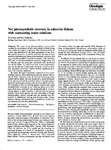
Transforms of a few major datapath blocks were derived in Sections 3.1 and 3.2. Now, we present the transforms of the remaining DA blocks. For presentation purposes, we initially assume that the sign bits are zero, or, equivalently, that the unsigned encoding is employed. AT of ROM. The content of ROM represents the bit multiplication of a constant Ak by bit vector xk, k = 1,...,N , Figure 5. It is easily verifiable from Figure 5 that, for the case N = 4, AT of ROM is given by
the previous blocks in the overall expression. The process is repeated until all the blocks are traversed, and all the outputs are expressed in terms of primary outputs of the circuit.
5. VERIFICATION OF DISTRIBUTED ARITHMETIC CIRCUITS Distributed Arithmetic (DA) refers to datapath architectures where the inner product of a vector by a constant is performed as a bit-serial operation [ l o ] . DA leads to efficient FPGA implementations of specialized DSP circuits like filters, but also of basic arithmetic functions, such as multipliers [3]. In filter applications, the word-level quantities are usually fractions. Hence, the signed numbers are represented as: x = -xO
+
A T ( R O M ) = A i x , + A , x , +...+ANxN
N = z A j ~ j , j=l
where each variable xj is one-bit wide and the coefficients A,, j = 1, ..., N are fractional numbers.
M-l
xi 2-' , and
................................
i=l ~
inpits
for unsigned numbers, the sign digit xo is not used. The calculation of inner products of a vector of constants A&with input vectors xk, k = 1, 2,. ..,h? M-l
y=tA,x,,
where
,
xj = - x j o + c x j , 2 - '
k=I
i=l
is performed bit-wise. Instead of inputting the whole M-bit xk vector in parallel, and then executing the multiplication by a M-bit constant Ak, all vectors are serially shifted in. In each cycle every shifted bit is "multiplied" in parallel by its constant Ak. Partial sums maintained in this way do not resemble the standard partial results of inner product calculations. The product: N
(
n
Figure 5: Distributed Arithmetic - ROM/Accumulator Structure MATS of Shift Registers. A shift register is a purely sequential circuit, consisting of a chain of storage cells. For each register, its discrete time defining equation is given as f[n] = a[n- 11, where the inputs a[n]are treated as bits. Building the shift register out of individual storage cells amounts to composing the word-valued transfer functions. For jrh shift register with M-1 stages, MATS at ] xj(M-l-k). time k is M A T S ( S R ( x j ) ) [ k =
y = Z A j x j = C A j - x , ; ~+ j=l
j=l
i=l
is transformed by changing the order of summation into
Equation 3 represents the form in which the inner product is calculated in the DA arithmetic. The multiplications in brackets, Equation 3, do not have to be calculated with multipliers. Instead, bit products can be pre-computed for all the possible combinations of bits x,, of vectors x,, and stored in ROM. Then, based on the actual combination of x,' among all x,'s, the corresponding ROM location is addressed [lo]. One possible hardware implementations of the DA inner product of four 4-bit vectors is presented in Figure 5.
MATS of Add-Accumulate Sum with Delay Element. MATS of this block is calculated by constructing and 1 solving the recurrence: f [ n ] = a[n]+- f [ n -11, f[O] = 0 ,
2
where variable a[n] is a word-level ROM output quantity and the initial condition in the register is 0. By solving the recurrence equation at time n, we get:
5.1 Transforms of Building Blocks of DA A typical DA circuit consists of the following blocks. Shift registers are used to serially input the vector bits. ROMs store the pre-computed partial sums, and addaccumulate loops maintain the partial results of the multiplication, Figure 5.
n
n
i=o
l=O
f [ n ] = C a [ i ] * 2 ' - " =Ca"]*2-'"-i'
,
5.2 AT Description of Complete Unsigned DA The transform of the complete circuit in Figure 5 is obtained by forward traversal, following Algorithm 1. The
352
Unsigned I Signed I Encoded Time # Terms ROM I AT 1 ROM I AT I ROM I AT [SI 4 16 60 32 64 8 64 0.5 8 256 120 512 128 128 128 2.0 16 16k 240 32k 256 8k 256 9.2 32 4G 480 8G 512 Table 2: AT vs. ROM Sizes in DA Implementations
intermediate variables will be substituted in all the expressions during the traversal. By substituting the outputs of the shift registers to the ROM inputs, we obtain the following timed expression: N
M A T S ( R O M ) [ k ] = x AJ . jx( M. - 1 - k ) . j=l
Next, substituting these variables, as the inputs to the addaccumulate sum results in:
6. Conclusions We presented two extensions to Arithmetic Transform that facilitate the compositional verification of sequential datapaths. The first extension makes the easy composition of transforms of individual blocks possible, while the second one allows sequential circuit representations. The compact canonical descriptions of large circuits can be quickly obtained by symbolic composition of transforms of individual blocks. Verification of highly sequential Distributed Arithmetic architectures was presented using these transforms. We intend to apply the method to the larger classes of sequential datapaths.
(4) The overall function AM-21 is completed at time instance M-2 as Equation 4 at time M-2: M-2 N
A T ( f ) = MATS(f)[M -21 = C C A j X j c M - l - k , 2 - ( M - ’ - P ) . k=O j=l
The result is the same as in Equation 3 (circuit specification) with the assumption that the sign bits are zero. T o verify that, we notice that by applying the change of indices of the first summation, the final AT is given by the expression that is equivalent to Equation 3:
7. References 5.3 AT Description of Signed and Encoded DA The signed DA algorithm differs from the previous case in (M-Z)‘h step added at the end of the execution, when the sign bits are incorporated. Then,f=AM-I] is obtained as N
A T ( f )= MATS(f)[M - 11 = - Z A j x j o +MATS( f ) [ M - 21. j=l
This expression is equal to Equation 3; hence, the equivalence is proven. The same approach was used to prove the equivalence of additional DA forms, including encoded DA circuits from [IO] that achieve the reduction in ROM sizes by alternative internal number encoding. Each new circuit can have a different, non-trivial DA implementation. The presented method can check the correctness of DA realization already on the algorithmic level. We implemented Algorithm 1 in Mathematica, for its ease of integration with the recurrence solver rsolve (by M. Petkovsek), already incorporated in Mathematica. The obtained representation is canonical and compact. By comparing the sizes (measured in words) of the resulting AT with the sizes of ROMs employed in DA circuits, as in Table 2, we observe that the overall AT representation is logarithmic in the size of a ROM. The last column presents worst case times spent on a 440MHz Ultra 10 workstation with 128MB of main memory in generating overall AT from ATs of DA components. As Mathematica is an interpreter with lots of overhead, these times could be greatly reduced by compiled code.
[l]M.D. Aagaard and C-J. H. Seger, “The Formal Verification of Pipelined Double-precision IEEE Floating-point Multiplier”, In Proc. IEEEIACM Int’l Con$ CAD, ICCAD, pp. 7-10, 1995. [2] R. Amirtharajah, T. Xanthopoulos and A. Chandrakasan, “Power Scalable Processing Using Distributed Arithmetic”, In Proc. ISLPED, pp. 170-175, 1999. [3] A. Berkeman, V. Owall, and M. Torkelson, “A Complex Multiplier with Low Logic Depth”, IEEE lnt’l. Con$ On Electronics, Circuits and Systems, pp. 47-50, 1998. [4] R.E. Bryant and Y-A. Chen, “Verification of Arithmetic Functions with Binary Moment Diagrams”, In Proc. of 32”“Design Automation Conference, pp. 535-541, 1995. [5] R. Drechsler, B. Becker and S. Ruppertz, “The K*BMD: A Verification Data Structure”, IEEE Design and Test of Computers, Vol. 14, No. 2, pp. 51-59, April-June 1997. [6] K. Hamaguchi, A. Morita and S. Yajima, “Efficient Construction of Binary Moment Diagrams for Verification of Arithmetic Circuits”, In Proc. ICCAD, pp.78-82, 1995. [7] J. D. Kim and S-K. Chin, “Assured VLSI design with formal verification”, In Proc. 12th Annual Con$ Computer Assurance, COMPASS, pp. 13 -22, 1997. [8] K. Radecka and Z. Zilic, “Using Arithmetic Transform for Verification of Datapaths via Error Modeling”, Proc. of VLSI Test Symposium, pp. 271-277,2000. [9] J. Smith and G. De Micheli, “Polynomial methods for allocating complex components”, In Proc. Design, Automation and Test in Europe, pp. 217 -222, 1999. [IO] S.A. White, “Applications of Distributed Arithmetic to Digital Signal Processing: A Tutorial Review”, IEEE ASSP Magazine, pp. 4-19, July 1989.
353