Articulated Object Registration Using. Simulated Physical Force/Moment for 3D Human Motion Tracking. Bingbing Ni, Stefan Winkler, and Ashraf Kassim.
Articulated Object Registration Using Simulated Physical Force/Moment for 3D Human Motion Tracking Bingbing Ni, Stefan Winkler, and Ashraf Kassim Department of Electrical and Computer Engineering National University of Singapore Singapore 117576 {g0501096, elews, eleashra}@nus.edu.sg
Abstract. In this paper, we present a 3D registration algorithm based on simulated physical force/moment for articulated human motion tracking. Provided with sparsely reconstructed 3D human surface points from multiple synchronized cameras, the tracking problem is equivalent to fitting the 3D model to the scene points. The simulated physical force/ moment generated by the displacement between the model and the scene points is used to align the model with the scene points in an Iterative Closest Points (ICP) [1] approach. We further introduce a hierarchical scheme for model state updating, which automatically incorporates human kinematic constraints. Experimental results on both synthetic and real data from several unconstrained motion sequences demonstrate the efficiency and robustness of our proposed method. Keywords: Iterative Closest Points, 3D Registration, Articulated Human Motion Tracking, Simulated Physical Force/Moment, Kinematic Constraints.
1
Introduction
Multiple view based, marker-less articulated human body tracking has attracted a growing research interest in the computer vision community through the last decade. This is because of the large number of potential applications such as motion capture, human computer interaction, virtual reality, smart surveillance systems etc. Due to the high dimensionality of human body motion, the 3D tracking problem is inherently a difficult problem. Image based methods were the first to be introduced in literature. Gavrilla and Davis [2] project a kinematic model onto each image plane and search for the best fit between the projected model and the image contours. Delamarre and Faugeras [3] create forces between the 3D human model and the detected image contours of the moving person to achieve their alignment. Instead of deterministic search algorithms, stochastic search algorithms are more likely to guarantee a global optimum. Deutscher [4] propose an annealed A. Elgammal et al. (Eds.): Human Motion 2007, LNCS 4814, pp. 212–224, 2007. c Springer-Verlag Berlin Heidelberg 2007 �
Articulated Object Registration Using Simulated Physical Force/Moment
213
particle filter approach for full body motion tracking. With as little as 100 particles, they can track full body motion in a stochastically optimal way. These particles are weighted by the similarity score between the extracted human contours and the synthetic silhouettes of the human model. Other methods based on belief propagation [5] were introduced to reduce the computational complexity. To address the self-occlusion problem, various 3D reconstruction-based algorithms have been proposed. Cheung [6] introduce a shape-from-silhouette method for full body tracking from both silhouette and color information. Based on the results of visual hull reconstruction, they segment the surface points of the human body into rigid moving body parts using color information. Thus the 3D articulated human body tracking problem is reduced to first estimating the rigid motion of each body part independently and then imposing constraints between the connected body parts. Cheung [7] also introduce a method based on volumetric reconstruction. Using an efficient voxel reconstruction technique, they fit ellipsoid models of human body parts into the reconstructed voxels in real-time. However this ellipsoid fitting approach fails when two body parts are too close to distinguish. In this paper we present a registration-based 3D articulated human body tracking method. The inputs to our system are sparsely reconstructed human surface points. We have developed a simulated physical force/moment based 3D registration method that performs in an Iterative Closest Points (ICP) flavor. Tracking is achieved by registering our human model to the reconstructed 3D points in each frame. Our algorithm incorporates different constraints of human motion kinematics in an automatic way, which makes the registration procedure more flexible. Our experiments show both the efficiency and robustness of our proposed method. The most related work to ours is performed by Delamarre and Faugeras [8], in which they apply similar ICP approach to track the 3D hand motion. However their work differs from ours in several ways. First, their inputs are dense reconstruction of the hand. Second, they use recursive dynamics algorithms to update the model state while we introduce a simple hierarchical model state updating scheme. Further more, no quantitative comparisons between their results and the ground truth data are given. The paper is organized as follows: Section 2 gives a brief introduction of our human model. The 3D registration method based on simulated physical force/moment is presented in detail in Section 3. Section 4 shows our tracking results for several human motion sequences with discussions. Section 5 concludes the paper.
2
3D Human Model
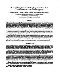
As shown in Fig. 1, the human body is represented by a combination of 10 cylinders. The torso can be regarded as a degenerate cylinder since it has an elliptical cross-section. Although more sophisticated tapered cylinders or super quadrics could be employed as models, our experiments show that the simple
214
B. Ni, S. Winkler, and A. Kassim
cylinder model is adequate for our tracking algorithm in terms of accuracy, and it also has the advantage of lower computational cost. For each part except the torso, a local coordinate frame is defined with the origin at the base of the cylinder. These origins also correspond to the center of rotation of each body part. The global coordinate system originates at the center of the torso. All body parts and corresponding parameters are indexed from 0 to 9 (cf. Fig. 1).
Fig. 1. 3D human model
Human kinematic knowledge is employed as a prior to define the degrees of freedom (DoF) for our human model. We incorporate 25 DoF: 3 DoF for upper arms, legs and head (rotating about their X, Y and Z axes), 1 DoF for lower arms and legs (they are only allowed to rotate about their X axes), and 6 DoF for the torso (global translation and rotation). With these definitions, the entire 3D pose of the body is determined by a 25D model state vector s = (t0x , t0y , t0z , θ0x , θ0y , θ0z , θ1x , θ1y , θ1z , θ2x , ...)T , which are the joint angles of shoulders, elbows, hips, and knees, plus the global position and orientation of the torso. The objective of our registration task is to find such a 25D state vector for the model that best fits the scene points (i.e., minimize some distance function between the model and the scene). To further constrain this high dimensional solution space as well as to eliminate the ambiguity during tracking, 2 types of motion constraints are imposed: 1. Kinematic constraints: The connectivity between adjacent body parts as well as the length constancy of the body parts are enforced through kinematic constraints. Each body part is only allowed to move according to its DoF (e.g., the lower arms are only allowed to rotate about their X axes). 2. Joint angle limits: For real human motion, the joint angles between adjacent body parts are within certain ranges (e.g., the elbow can only rotate around its X axis about 135 degrees). Therefore it would be necessary to incorporate this constraint to further reduce the solution space.
Articulated Object Registration Using Simulated Physical Force/Moment
215
One property of our simulated physical force/moment based registration algorithm is that we can incorporate the above constraints automatically during iterations, which will be described in detail in the following section.
3
Registration Using Simulated Physical Force/Moment
Given a set of 3D surface points for each frame and a 3D human model composed of a set of connected body parts, the tracking problem is equivalent to a registration problem: find a suitable configuration of the state vector s to minimize some distance function between the human model and the 3D scene points. The distance metric we choose here is the average Euclidean distance between 3D scene points and their assigned parts of the human model (the point-cylinder distance): 1 � � �Pi − Pi,m(π(i)) �2 (1) D(M, S) = N i � �2 , j = 0, 1, ..., 9 π(i) = argminj �Pi − Pi,m(j)
(2)
where M and S denote the model and the set of scene points respectively; N is the number of scene points; m(j) denotes the j th model part; Pi is a 3D scene � is its corresponding (closest) point on the j th model part; π(i) point and Pi,m(j) is the index of the model part which Pi is assigned to (i.e., with the closest distance). 3.1
Iterative Closest Points (ICP)
The well-known iterative closest points (ICP) algorithm is commonly used to coarsely align a rigid model with 3D scene points in an iterative manner: 1. For each 3D scene point, find its closest point on the model; calculate the local displacement between the model and the scene point. 2. Estimate the transform by integrating the local displacement over the entire object. 3. Apply the transform to the model. 4. Repeat above steps until convergence (i.e., the displacement between the scene and model is small or the consecutive estimated updating transforms are negligible). The original version of the ICP algorithm is only designed for rigid models. Recently some variations of the ICP algorithm were proposed to deal with articulated objects. Demirdjian [9] presents a method that first applies ICP to each rigid body part, then linearly projects each independent transform into the solution space (i.e., the solution space that constrains the connectivity of the articulated body parts). Knoop [10] model several different types of joint constraints to enforce the articulated property after estimating the transform for each part independently. These independent transform estimation/solution
216
B. Ni, S. Winkler, and A. Kassim
space projection based methods can easily become stuck in local minima. We therefore present a novel ICP-flavored, simulated physical force/moment based registration method, which iteratively aligns the model with the 3D scene points in a global and hierarchical style. 3.2
Registration
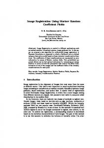
Our basic idea comes from the observation of the physical world. Suppose a displacement between a scene point and its closest point on the model creates a simulated physical force. This force generates two effects on the model: translation velocity and angular moment to pull/rotate the model into the alignment with the 3D scene point. Fig. 2 illustrates the force/moment created by the displacement between a scene point and its closest point on the model.
Fig. 2. Translation and rotation created by the simulated physical force/moment
→ −−→ − The force can be expressed as F = P � P , where P is the scene point and P � − → − → is its closest point on the model. The moment is denoted as M = F L, where L → − is the vertical distance from force F to the rotation center. The magnitude of the translation and rotation vectors generated is proportional to the magnitude → − − → → → of the physical force/moment, namely: − v = ρ F and − ω = λM , where ρ and λ are some small coefficients. As in the ICP, we iteratively compute the closest points and then update the model state according to the estimated transform. During each iteration step, the displacements between all 3D scene points and the model are calculated, and all forces and moments are summed up, resulting in a translation and a rotation vector to align the model with the 3D scene points: � � − → → − vi = ρFi (3) (δtx , δtx , δtz )T = i
and (δθx , δθx , δθz )T =
� i
i
− → ωi =
� −→ λMi
(4)
i
−→ → − Here Fi and Mi are the simulated physical force and moment created by the scene point Pi . With enough iterations, the misalignment between the model and the
Articulated Object Registration Using Simulated Physical Force/Moment
217
Fig. 3. Alignment procedure between the model and the scene points
Fig. 4. Human model hierarchy tree
3D scene points will be minimized, and the overall physical force/moment will be balanced, indicating convergence. Fig. 3 illustrates the alignment procedure between the model and the scene points. Given a set of articulated cylinder model parts, we start with assigning each scene point to its closest model part. However, instead of applying the above method to each body part independently, we adopt a hierarchical approach for applying the transform to the human model, which has the following intuition: Suppose a physical force is applied to the right lower arm of the model; this force will not only create the angular moment for the right lower arm to rotate around the elbow, but will also contribute to the right upper arm’s rotation about the shoulder, as well as the global rotation and translation of the torso. Our hierarchical updating approach is consistent with this key observation. The human model will be treated as a hierarchy tree with its root at the torso, and it has sub-trees rooted at the right and left upper arms, the right and left upper legs, and the head. Fig. 4 illustrates the hierarchy of the human model. When estimating the transform associated with a certain body part, the physical forces applied to all body parts in its group will be integrated. For example, when calculating the global translation and rotation (δt0x , δt0y , δt0z , δθ0x , δθ0y , δθ0z )T , the forces applied to all body parts will be counted as follows: ⎞ − → ∈m(j) δt0x � Fi � → − ⎝ δt0y ⎠ = λj0 Fi j i δt0z ⎛
(5)
218
B. Ni, S. Winkler, and A. Kassim
and
⎛
⎞ −→ ∈m(j) δθ0x � Mi� −→ ⎝ δθ0y ⎠ = ρj0 Mi j i δθ0z
(6)
where λj0 and ρj0 (j = 0, 1, 2...9) are some weighting factors. Similarly, when estimating the rotation (δθ1x , δθ1y , δθ1z )T of the right upper arm about the right shoulder (there would be no translation for the right upper arm as defined by its DoF), the physical forces applied to the right upper arm and right lower arm will be counted: ⎛ ⎞ −→ −→ Mi ∈m(1) Mi ∈m(2) δθ1x � � − → −→ ⎝ δθ1y ⎠ = ρ11 Mi + ρ21 Mi (7) i i δθ1z We further concatenate the transform vectors estimated for each body part to obtain the 25D updating vector δs = (δt0x , δt0y , δt0z , δθ0x , δθ0y , δθ0z , δθ1x , δθ1y , δθ1z , δθ2x ...)T . Obviously the DoF of each body part is preserved and the articulated structure of the human model is maintained implicitly in this updating scheme.
(a) Iteration 4
(b) Iteration 6
(c) Iteration 10
Fig. 5. Example of the iterative registration procedure for our human model (The scene points are plotted by green stars. The simulated forces between the model and the scene points are represented by blue lines. The human model is represented by red cylinders.)
Furthermore, the kinematic constraints and joint angle limits can be incorporated in this framework automatically. Given the original state vector s and the updating vector δs generated by our registration algorithm, we can clamp the new state vector to avoid the violation of any constraint by the following inequality: (8) slb ≤ s + δs ≤ sub where slb and sub are the lower and upper bounds of the joint angles. Fig. 5 illustrates a few iterations of a typical registration procedure for our human model by this hierarchical updating scheme.
Articulated Object Registration Using Simulated Physical Force/Moment
219
Fig. 6. A diagram for the tracking procedure
3.3
Tracking
The tracking procedure is straightforward: given a new frame of reconstructed scene data, we start from the registered state of last frame st−1 and iteratively apply the simulated physical force/moment based registration algorithm until convergence. We choose the convergence criteria as follows: The distance function between the model and the scene is smaller than some threshold, and the estimated state transforms for consecutive iteration steps become negligible. Fig. 6 gives a detailed diagram of the tracking procedure.
4
Results and Discussion
We validate our proposed method using both synthetic and real data. In total about 1000 frames from both synthetic and real sequences are tested. For the synthetic data, the 3D surface points are generated by the 3D modeling software package Maya, combined with the motion sequences provided by the CMU motion capture database [11]. Each of the sequences spans hundreds of frames during which the subject performs unconstrained, fully articulated motions such as walking and dancing. Gaussian noise is added to the 3D coordinates of the original data points to simulate reconstruction errors. We then compare the joint angles estimated by our method with the ground truth from the database. Several examples of the tracking results of the synthetic sequences are shown in Figs. 7 and 8. It can be observed that our registration/tracking algorithm performs well for most poses. In Fig 8(a), the two upper arms are tightly coupled with the torso, which makes them difficult to distinguish, however our algorithm
220
B. Ni, S. Winkler, and A. Kassim
(a)
(b)
(c)
(d)
Fig. 7. Examples of the tracking results of the walking sequence. The top row shows the synthetic scenes created with Maya, from which the 3D surface points are sampled. The bottom row shows the corresponding registration results. The scene points are plotted as green stars, and the human model is represented by red cylinders.
performs properly under this scenario. Another case of robustness is demonstrated in Fig 8(b), where the arms are folded very close to each other, yet the pose is correctly tracked. Besides its reliable performance under such conditions, our registration/tracking algorithm is also flexible when it comes to more unusual human poses; Figs. 8(c) and 8(d) show such examples. Examples of the tracking results of a real motion sequence are shown in Fig. 9. This sequence shows a female dancer performing various movements. Using 7 synchronized cameras surrounding the scene, the human surface points are obtained by visual hull reconstruction [12]. Although ground truth data is not provided, we can still evaluate the results qualitatively. While the tracking results are good overall, the loose dress of the dancer causes problems in the reconstruction accuracy in some cases. Fig. 10 compares the ground truth with the estimated joint angles in the walking and dancing sequences. It can be observed that in the walking sequence our estimated joint angles of the left knee follow the periodical motion of the left leg very accurately. Fig. 11 shows the histograms of the root mean squared error (RMSE) for the different sequences. The average RMSE of the estimated joint angles for both sequences are about 8 and 16 degrees, respectively. The larger errors in
Articulated Object Registration Using Simulated Physical Force/Moment
(a)
(b)
(c)
(d)
Fig. 8. Examples of the tracking results of the dancing sequences
(a)
(b)
(c)
(d)
Fig. 9. Examples of the tracking results of the real sequence
221
222
B. Ni, S. Winkler, and A. Kassim
(a) Joint angle of the left knee in the walking sequence.
(b) Joint angle of the right elbow in the dancing (1) sequence.
Fig. 10. Comparison between the ground truth and experimental results for two joints
(a) Walking sequence (450 frames, average RMSE=8.2 degrees).
(b) Dancing sequences (480 frames, average RMSE=16.1 degrees).
Fig. 11. RMSE for synthetic sequences
the dancing sequences are mainly due to the coarseness of our human model; for example, the subject’s upper torso bends forward, but our model fits the upper/lower torso as a single rigid body part, resulting in estimation errors. Lack of minor extremities (e.g., hands and feet) also induces further estimation errors. One can notice in Fig. 5(c) that the points of the feet pull the lower legs slightly away from their actual positions. In our future work, we will refine our human model to avoid this kind of errors, i.e., split the torso into two parts, add parts for feet and hands etc. In normal cases when the body parts are not close to each other (i.e., arms and legs are stretched out), a roughly aligned pose is adequate for accurate initialization even if the displacements between the scene points and human model are large. Fig. 12 shows 3 initialization results starting from the initial model pose on the left.However, for some poses, especially when two body parts
Articulated Object Registration Using Simulated Physical Force/Moment
(a)
(b)
(c)
223
(d)
Fig. 12. Examples of the initialization results. The left figure shows the initial pose of the model. The other 3 figures show the converged results of the initialization. The scene points are plotted as blue stars, and the human model is represented by red cylinders.
are too close to distinguish or have sharp joint angles, the initialization can become trapped in a local minimum. To address this problem, various methods can be used. We are investigating 3D shape context [13,14] to coarsely detect the human posture in the initial frame. The 3D shape descriptor calculated from the reconstructed points of the first frame will be compared with all candidates in a small pre-generated shape descriptor database. The configurations with the best matching scores can then be used to initialize the model state vector.
5
Conclusions
We have introduced a simulated physical force/moment based 3D registration method, which we have applied to articulated human motion tracking. We also presented a hierarchical model state updating scheme that incorporates different human kinematic constraints in an automatic way. Our experiments on sequences of unconstrained human motion show the robustness and effectiveness of our proposed method. Acknowledgments. The synthetic motion key data used in this project was obtained from mocap.cs.cmu.edu. The multiple-video data used here are from INRIA Rhone-Alpes multiple-camera platform Grimage and PERCEPTION research group. The database is available at https://charibdis.inrialpes.fr.
References 1. Besl, P., McKay, H.: A method for registration of 3-D shapes. IEEE Transactions on Pattern Analysis and Machine Intelligence 14(2), 239–256 (1992) 2. Gavrila, D., Davis, L.: 3-D model-based tracking of humans in action: A multi-view approach. In: Proc. IEEE Conference on Computer Vision and Pattern Recognition, San Francisco, CA, USA, pp. 73–80. IEEE Computer Society Press, Los Alamitos (1996)
224
B. Ni, S. Winkler, and A. Kassim
3. Delamarre, Q., Faugeras, O.: 3D articulated models and multi-view tracking with silhouettes. In: Proc. IEEE International Conference on Computer Vision, Corfu, Greece, vol. 2, pp. 716–721. IEEE Computer Society Press, Los Alamitos (1999) 4. Deutscher, J., Blake, A., Reid, I.: Articulated body motion capture by annealed particle filtering. In: Proc. IEEE Conference on Computer Vision and Pattern Recognition, Hilton Head, SC, USA, vol. 2, pp. 126–133. IEEE Computer Society Press, Los Alamitos (2000) 5. Han, T., Huang, T.: Articulated body tracking using dynamic belief propagation. In: Sebe, N., Lew, M.S., Huang, T.S. (eds.) Proc. IEEE International Workshop on Human-computer Interaction. LNCS, vol. 3766, pp. 26–35. Springer, Heidelberg (2005) 6. Cheung, K., Baker, S., Kanade, T.: Shape-from-silhouette of articulated objects and its use for human body kinematics estimation and motion capture. In: Proc. IEEE Conference on Computer Vision and Pattern Recognition, Madison, Wisconsin, USA, vol. 1, pp. I–77–I–84 (2003) 7. Cheung, K., Kanade, T., Bouguet, J., Holler, M.: A real time system for robust 3D voxel reconstruction of human motions. In: Proc. IEEE Conference on Computer Vision and Pattern Recognition, Hilton Head, SC, USA, vol. 2, pp. 714–720. IEEE Computer Society Press, Los Alamitos (2000) 8. Delamarre, Q., Faugeras, O.: 3D articulated models and multi-view tracking with physical forces. Computer Vision and Image Understanding 81(2), 328–357 (2001) 9. Demirdjian, D.: Enforcing constraints for human body tracking. In: Proc. Workshop on Multi-Object Tracking (2003) 10. Knoop, S., Vacek, S., Dillmann, R.: Modeling joint constraints for an articulated 3D human body model with artificial correspondences in ICP. In: Proc. IEEERAS International Conference on Humanoid Robots, Tsukuba, Japan, pp. 74–79 (December 2005) 11. Lab, C.G. 12. Franco, J., Boyer, E.: Exact polyhedral visual hulls. In: Proc. British Machine Vision Conference (2003) 13. Belongie, S., Malik, J.: Matching with shape context. In: Proc. IEEE Workshop on Content-based Access of Image and Video Libraries, Hilton Head, SC, USA, pp. 20–26. IEEE Computer Society Press, Los Alamitos (2000) 14. Kortgen, M., Park, G., Novotni, M., Klein, R.: 3D shape matching with 3D shape context. In: Proc. 7th Central European Seminar on Computer Graphics (April 2003)