Aspect-Oriented Domain-Specific Modeling Jeff Gray, Ted Bapty, Sandeep Neema, Aniruddha Gokhale Institute for Software Integrated Systems (ISIS) Vanderbilt University, Nashville TN {jgray, bapty, neemask}@vuse.vanderbilt.edu
ABSTRACT Aspect-Oriented Domain-Specific Modeling (AODSM) represents the nexus between Aspect-Oriented Programming (AOP) and Model-Integrated Computing (MIC). Recently, research in the area of aspect-oriented design has concentrated on the important issues of notational and diagrammatic representation. However, the research described in this paper has brought the benefits of aspect-orientation to the modeling process itself. This paper describes numerous facets of AODSM, including: domain-specific weavers, the Embedded Constraint Language (ECL), code generation issues within a metaweaver framework, and a comparison between AODSM and AOP. An example of the approach is provided, as well as a description of several future research topics for extending the flexibility within AODSM.
Keywords aspect-oriented software development, computing, domain-specific visual languages
model-integrated
1. INTRODUCTION Even though the general notion of separation of concerns is an old idea, one can witness the nascence of a research area devoted to the investigation of new techniques to support advanced separation of concerns. It has been recognized by numerous researchers (e.g., [Tarr et al., 99], [Bergmans and Aksit, 01], [Kiczales et al., 01], [Lieberherr et al., 01]) that the software modularization constructs developed over the past quarter-century are sometimes inadequate for capturing certain types of concerns. This has serious consequences with respect to modular composition. As noted in [Tarr et al., 99], previously defined modularization constructs are most beneficial at separating concerns that are orthogonal. However, these constructs often fail to capture the isolation of concerns that are non-orthogonal. Such concerns are said to be crosscutting, and their representation is scattered, and tangled among the descriptions of numerous other concerns. Crosscutting concerns are denigrated to second-class citizens in most languages (i.e., there is no explicit representation for modularization of crosscutting concerns). As a result, crosscuts are difficult to compose and change without invasively modifying
[email protected]
the description of other concerns (i.e., crosscuts are highly coupled with other concerns). Recent research efforts, under the general name of AspectOriented Software Development (AOSD) [AOSD, 02], are exploring fundamentally new ways to carve a system into a set of elemental parts in order to support crosscutting concerns. The goal is to capture crosscuts in a modular way with new language constructs called aspects. In the nomenclature of AOSD, a pointcut specifies a collection of points in the dynamic execution of a program that are affected by a specific crosscutting concern, and advice represents the behavior to add to a pointcut [Kiczales et al., 01]. Separation of concerns often necessitates subsequent integration. Whereas AOP provides the capability of separating numerous concerns during development, the effects of the crosscuts must be integrated back into the solution space. The goal of the separation is to improve the conceptual ability of programmers during development– the end result at run-time, however, will certainly have crosscutting concerns that are transparent. As David Weiss states, “ At runtime, one might not be able to distinguish what criteria were used to decompose the system into modules” [Hoffman and Weiss, 01]. In AOP, a translator called a weaver is responsible for taking code specified in a traditional programming language, and additional code specified in an aspect language, and merging the two together. Because the aspect code describes numerous behaviors that crosscut a system, the concerns must eventually be integrated into the base. This is the purpose of the AspectJ weaver – it integrates aspects into the execution points of the base code [Kiczales et al., 01].
1.1 Research Objectives This paper describes research on advanced separation of concerns at the system modeling level, and the construction of support tools that facilitate the elevation of crosscutting modeling concerns to first-class citizens. The contributions of this research can be summarized by two objectives:
•
Raise Aspect-Oriented (AO) concepts to a higher level of abstraction An AO approach can be beneficial at different stages of the software lifecycle and at various levels of abstraction; that is, it also can be advantageous to apply AO at levels closer to the problem space (e.g., analysis, design, and modeling), as opposed to the solution space (e.g, implementation and coding). Whenever the description of a software artifact exhibits crosscutting structure, the principles of modularity espoused by AO offer a powerful technology for supporting separation of concerns. This has been found to be true also in the area of domain-specific modeling. Although there have been other efforts that explore AO at the design and analysis levels (see Section 1.5.1 for more details), the work described in [Gray et al., 01] represents one of the earliest occurrences in the literature of an actual aspectoriented weaver that is focused on system modeling issues, rather than topics that are applicable to traditional programming languages.
•
Assist in the creation of new weavers using a generative framework Because the syntax and semantics of each modeling domain are unique, a different weaver is needed for each domain. A metaweaver framework has been created as an aid toward the rapid construction of new domain-specific weavers. This framework uses several code generators that take metalevel specifications, described in a Domain-Specific Language (DSL), as input. The generators produce code that serves as a hook into the framework.
These two objectives provide a contribution toward the synergy of AOSD and Model-Integrated Computing (MIC) [Sztipanovits and Karsai, 97]. This union assists a modeler in capturing concerns that, heretofore, were very difficult, if not impossible, to modularize. A key benefit is the ability to explore numerous scenarios by considering crosscutting modeling concerns as aspects that can be rapidly inserted and removed from a model. The remainder of this section provides background information required to understand the AODSM approach presented in this paper.
1.2 MIC and the Generic Model Editor In Domain-Specific Modeling (DSM), expressive power is gained from using notations and abstractions that are aligned to a specific problem domain. Often, graphical representations are provided for modeling domain abstractions. In domain-specific modeling, a design engineer describes a system by constructing a visual model using the terminology and concepts from a specific domain. Analysis can then be performed on the model, or the model can be synthesized into an implementation.
At ISIS, MIC has been refined over many years in order to assist in the creation and synthesis of computer-based systems. A key application area for MIC is in those systems that have a tight integration between the computation structure of a system and its physical configuration [Sztipanovits and Karsai, 97]. In such systems, MIC has been shown to be a powerful tool for providing adaptability in frequently changing environments. An example of the flexibility provided by MIC is documented in [Long et al., 98], where an installed system at Saturn was shown to offer significant improvements in throughput by being able to adapt to changes in business needs and the physical environment (i.e., the reconfiguration of an automobile manufacturing plant). A specific instance of the type of domain-specific modeling supported by MIC is implemented using a core tool – the Generic Model Editor (GME) [Lédeczi et al., 01]. The GME is a modeling environment that can be configured and adapted from metalevel specifications (this is called the modeling paradigm) that describe the domain [Nordstrom et al., 99]. In using the GME, a modeler loads a modeling paradigm into the tool. This provides an environment containing all of the modeling elements and valid relationships that can be constructed in a specific domain.
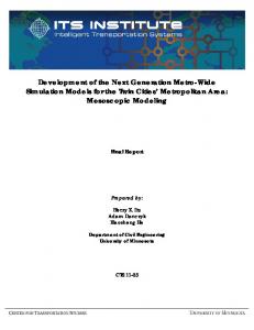
1.3 Design Space Exploration A beneficial approach toward domain-specific modeling considers the creation of a base model for representing a family of related systems (e.g., a product-line architecture [Clements and Northrop, 01]). In such an approach, a design space corresponds to a set of implementation alternatives that are available within the product family. The selection of a fixed-point, among the set of possible alternatives from the base model, must be explored prior to model synthesis [Neema, 01]. Design space exploration is an iterative process that selectively evaluates a set of constraints that are chosen by a modeler using a tool. The exploration of a design space requires the existence of constraints that are dispersed throughout a model. Constraints codify properties of the model that must be satisfied during exploration. Each iteration of the exploration prunes the design space further. Focusing the exploration on different sets of constraints can lead the exploration and pruning algorithms along different elaborations of synthesis. The Multigraph Constraint Language (MCL) is an extension of the Object Constraint Language (OCL) [Warmer and Kleppe, 99]. MCL is supported within the GME in order to define the domain rules that are in a modeling paradigm. MCL constraints also can appear as attributes within a model to assist in the design space exploration. The MCL is used to denote pre/post-conditions, class invariants, and even guard conditions for state machines. The MCL is a purely declarative modeling language; it is not a programming language. An important feature of the MCL is that it does not introduce side effects into the underlying model. An example of a latency constraint, from a domain that was developed for Automatic Target Recognition (ATR), is illustrated in Figure 1. This particular constraint defines the latency for the top-level of the model to be less than 100.
1.5.1 Aspect-Oriented Modeling: Adjective or Verb?
Figure 1: A Latency Modeling Constraint
1.4 Crosscutting Constraints The utility of specifying constraints within a model, however, is often diminished due to their scattering throughout the model hierarchy [Gray et al., 01]. It is often the case that the metamodel forces the emergence of a “ dominant decomposition” (i.e., the primordial criteria for modular decomposition) [Tarr et al., 99] that imposes the subjugation of other concerns, such as those captured by constraints. Consequently, constraints represent a type of crosscutting concern. In conventional system modeling tools, any change to the intention of a system property requires visiting and modifying each constraint, for every context, representing the property. This would require the modeler to “ drill-down” (i.e., traverse the hierarchy by recursively opening, with the mouse, each submodel), manually, to many locations of the model. It is not uncommon for a model in the GME to contain hundreds of different modeling elements with hierarchies that are ten or more levels deep. The interdependent nature of each constraint makes change maintenance a daunting task for anything but a simple model. The benefits of a single model representation of a product family are nullified. The “ Parnasian” objectives of changeability, comprehensibility, and independent development are all sacrificed in the presence of crosscutting constraints [Parnas, 72]. This paper presents a technique for modularizing the concerns represented in these crosscutting constraints.
1.5 Related Work In this section, two specific areas of related work are briefly mentioned. In addition to describing the work, reasons are given for their inability to offer a solution to the problem of handling crosscutting constraints during the actual system modeling process.
A growing area of research is concentrated on bringing aspectoriented techniques into the purview of analysis and design. The prominent work in that area has been published as [Clarke et al., 99], [Clarke and Walker, 01], and [Clarke, 02] (also, see the workshops in this area at the First Conference on Aspect-Oriented Software Development). A focal point of these efforts is the development of notational conventions that assist in the documentation of concerns that crosscut a design. These notational conventions advance the efficiency of expression of these concerns in the design. Moreover, they also have the important trait of improving the traceability from design to implementation. Without the introduction of aspect-oriented notations into popular modeling languages (like UML), there could be a mismatch (in some cases) when an object-oriented design is implemented using an aspect-oriented programming language. In the absence of these new notations, the intent of a crosscut is captured in an object-oriented design in a way that is awkward. This progression of a paradigm, from implementation to design, is very similar to the evolution of the object-oriented and structured paradigms moving from the implementation level to the design level. The movement of the paradigm up the stages of the software lifecycle aids in reducing the semantic gap between each phase. Although these current efforts do well to improve the cognizance of AO at the design level, they treat the concept of AspectOriented Design (AOD) as an “ adjective.” This is to say that the focus has been on the notational, semantical, and decorative attributes concerned with aspects and their representation within UML. A contribution of this paper is to consider AODSM as a “ verb.” That is, viewing AO as a mechanism to improve the modeling task, itself, by providing the ability to quantify properties across a model during the system modeling process. This action is performed by utilizing a weaver that has been constructed with the concepts of modeling in mind. A research effort that also seems to have this goal in mind can be found in [Ho et al., 02]. Although they state that their approach is aspectoriented, their work seems more aimed at providing a transformation tool that reifies design patterns at the level of object-oriented design.
1.5.2 Concern Separation in the GME Research and development with the GME has incorporated several powerful techniques (e.g., viewpoints and type hierarchies) for dealing with the problem of separation of concerns at the modeling level. These techniques generally fail, however, at capturing modeling concerns that are crosscutting. As models grow in size and complexity, it becomes unmanageable to view the contents of a model in its entirety; there are just too many participating entities. The concept of viewpoints has been researched frequently as a topic within requirements engineering [Nuseibeh et al., 94]. Plainly stated, “ A view is a description of the system relative to a set of concerns from a certain viewpoint” [Hilliard, 99]. The GME supports the concept of a viewpoint as a first-class modeling construct. This assists a modeler in separating the concerns of multi-perspective views [Lédeczi et al., 01]. Each
GME viewpoint describes a partitioning that selects a subset of entities as being visible. Although they offer a powerful conceptualization for concern separation, viewpoints, however, do not fit completely within the definition of aspects (at least in the way that they are defined within the AOP community). Using only viewpoints, for example, a modeler cannot quantify over a model’ s join points and apply advice. The key parts of AO, as enumerated in [Kiczales et al., 01], are not fully present in viewpoint-oriented techniques. Types and prototypes are two capabilities that can be very useful in modeling. Modeling tools that support these concepts provide mechanisms to share a common description among numerous objects. A prototype is a representative example of a group of objects that can be reused (or cloned) at other places in the application model. The idea, as it applies to modeling, borrows from the research that has been done in the area of prototypebased programming languages [Craig, 00]. The GME supports the idea of types and prototypes in order to provide a facility to modelers for categorizing and managing general modeling concepts [Lédeczi et al., 01]. Creating clones of prototypes is a simple operation in the GME – the prototype is selected and then dragged to the destination. Clones have the same set of attributes as their prototypes. By modifying the value of an attribute of some prototype, the change propagates to all clones. As in all prototype-based programming systems, however, the clones are not identical mirror images of their prototypes. It is possible to overwrite any attribute value in the clone, and expect the new value not to be rewritten by the propagation mechanism. The prototype-clone relationship is preserved for the full lifetime of these objects, which distinguishes cloned objects from simple copies. Consider the fact that many programming languages support the notion of typing, yet, the modularization of crosscutting concerns cannot be captured using typing alone. The same can be said for the typing facility provided within GME. It does support a useful feature of generalization and reuse of properties, but it fails to provide the kind of quantifying separation found in AOP. The combination of viewpoints and types within the GME, and the aspect weaver described herein, provides a modeler with the flexibility needed to examine the effect of numerous modeling scenarios. More importantly, these three techniques promote the ability of a modeler to make changes readily within the model – a desirable characteristic of any method that supports concern separation.
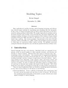
weavers are required. As Figure 2 illustrates, the domain for Automatic Target Recognition (i.e, “ ACS ATR”) needs its own specialized weaver, as does the BBN Unmanned Aerial Vehicle (UAV) domain, and the Boeing BoldStroke domain (see the example at the end of the paper).
ACS
BBN
Boeing
ATR
UAV
BoldStroke
+
+
ATR specific weaver
+
BBN specific
BoldStroke specific
weaver
weaver
Figure 2: Separate Weavers for Different Paradigms The GME has the capability to persistently store models using XML. To better understand the need for multiple weavers, consider the XML document in Figure 3 (this XML corresponds to the strategy provided later in Figure 13). The document has distinctly named regions with respect to the kind of elements being presented in the domain (e.g., “ Component”), as well as roles (e.g., “ ComputeMethod”), name, and even attributes (e.g., “ WCET”).
InertialSensor compute
The remainder of this paper is devoted to a description of the AODSM process.
2
2. DOMAIN-SPECIFIC WEAVING In the definition of a modeling paradigm, concepts from the domain are specified using a graphical modeling language. Different domains will have different dominant decompositions and different crosscutting concerns. Consequently, different
Figure 3: BoldStroke/CCM XML Model
Further consider the XML fragment in Figure 4. It also has its own unique modeling entities (e.g., “ State,” “ Transition,” “ Guard”). It should be noted that the same XML DTD is used in both Figure 3 and Figure 4. However, the modeling concepts captured in each model are significantly different. The quoted strings in some of these models (e.g., the “ kind” slots) show that something “ meta” is truly happening. Because each new GME metamodeling paradigm introduces different types of modeling elements, syntax, and semantics, different weavers are needed for each new paradigm. The situation is similar to the reason a different compiler is needed for a new programming language – the syntax and semantics varies too much between each language to permit a single instance of a generalized translator that compiles multiple languages.
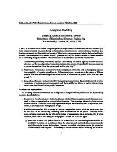
As intimated earlier, the output of a domain-specific weaver is a new GME model that contains constraints that have been weaved (i.e., the input to the weaver may be a base model that is void of any constraints). The newly created constrained model can then be passed on to the design-space exploration tool, as mentioned previously in the introduction. The content inside the box of Figure 5 represents the contributions toward AODSM. The design space exploration research is a previous effort that provided the initial motivation for exploring this new area. For more details on strategies and specification aspects, see [Gray et al., 01].
Domain-Specific Strategies frameRate Range1-7 Transition
Models Specification Aspects
latency > 25 frameRate=4
Constrained Models
Figure 4: BBN/UAV XML Model The AODSM approach that we are using can be summarized by the diagram in Figure 5. In this figure, new weavers are created by integrating domain-specific strategies into a metaweaver framework (shown in the top-part of Figure 5). A strategy specifies a heuristic (e.g., processor assignment, as shown in an upcoming example) for a specific modeling paradigm. Strategies are specified in a Domain-Specific Language (DSL) called the Embedded Constraint Language (ECL); see the next section for information on ECL. A generator translates each strategy into C++, such that an instantiation of the metaweaver framework is created. The instantiation of the framework (with a set of strategies) produces a new domain-specific weaver. After a weaver is created for a specific domain, GME models (represented in that domain) can be weaved with specification aspects. A specification aspect is an AODSM neologism that is related to the AOP idea of a pointcut. Specification aspects identify specific points in a model that are affected by a crosscutting modeling concern.
Design-Space Exploration and Pruning
Figure 5: Summary of AODSM Process
3. Embedded Constraint Language Weavers are specified using our Embedded Constraint Language (ECL). ECL is an extension (and subset) of the MCL (and OCL) for operations on modeling objects. This language allows the weaver designer to specify the traversal of models, computations upon the structure and attributes, and subsequent modification s to the models. The modifications can be the addition of constraint objects, addition/modification of attributes to existing models, and addition of domain-specific modeling objects. A short description of the ECL follows. For more details, see [Gray, 02].
Table 1: Included OCL Operators Arithmetic Operators +, -, *, /, =, , =, Logical Operators and, or, xor, not, implies, if/then/else
procedure calls. Recursion is also supported in ECL. Circular dependencies are possible (of course, the strategy must specify a termination condition in order for the strategy to complete its processing). Table 2: ECL Model Operators Aggregates
folders, models, atoms, attributes, connections
Collection Operator & Property Operator Connections -> . Standard OCL Collection Operators collection->size() : integer collection->forAll(x | f(x) ) : Boolean
connpoint, target, refs, resolveRefeeredID, resolveIDReferred Transformation
addAttribute, addAtom, addModel, addConnection, removeNode
collection->select(x | f(x) ) : collection collection->exists(x | f(x) ) : Boolean
Selection
findFolder, findModel, findAtom, findAttributeNode The ECL supports many of the basic language constructs found in the OCL, as categorized in Table 1. There are a few things that distinguish ECL from OCL and MCL: •
•
•
ECL provides a set of operators for navigating the hierarchical structure of a model (see Table 2). These aggregate operators can be applied to first-class model objects (e.g., a container model or primitive model element) in order to obtain reflective information needed in either a strategy or specification aspect (e.g., findModel, getID, findAttribute). These operators can be considered as reflective and likened to introspective operators in Java (e.g., getName, getType, getInt); i.e., they are reflective to the internal representation used in the GME. Traditionally, OCL has been used as a declarative language to specify properties of UML diagrams [Warmer and Kleppe, 99]. The use of ECL requires the capability to introduce side-effects into the underlying XML model. This is needed because the strategies often specify transformations that must be performed on the model. This requires the ability to make modifications to the model as the strategy is applied. Therefore, ECL supports an imperative procedural style with numerous operations that can alter the state of the model (e.g., addAtom, addAttribute, removeChild). Because the underlying model hierarchy is stored as an XML file, these functions are often implemented as wrappers for the specific calls that are needed to the XML Document Object Model (DOM). The procedural nature of ECL permits the dependency between strategies. Strategies can be chained together as
General
id, parent, getID, getInt, getStr
A specific example of the application of the ECL can be found in the upcoming Examples section.
4. COMPARISON TO AOP Domain-specific weavers rely on specification aspects and strategies to carry out their duty. Specification aspects, similar in intent to pointcuts in AspectJ [Kiczales et al., 01], are used to describe where the concern will be applied in the model, and strategies describe how a concern is applied in the context of a particular node in the model. Several comparisons can be made between the approach to AODSM, as described in this paper, and traditional AOP (see Figure 6). The illustration in Figure 6a depicts a pointcut that is associated with a specific piece of advice. The effect of this association is the quantification of a concern over multiple join points [Filman and Friedman, 00]. The pointcut construct in AspectJ identifies several join points, and the advice construct describes the additional code to run at those join points. Comparatively, the box in the bottom-right of Figure 6b represents a subset of a specification aspect. In this specification aspect, a predicate within the select statement instructs the weaver to collect all nodes in the model that are of kind “ StateFlow” and have a name that matches “ Model*.” Such a statement has a direct correspondence to a pointcut (as in AspectJ)
that picks out specific points in the execution of a program satisfying some condition. The specification aspect also describes the strategy that is to be invoked on each node selected from the predicate. As the strategy is applied at each node, the graph is transformed according to the intent of the strategy. This has a direct correspondence to the association of pointcuts with advice in AspectJ, and how advice affects the execution of the program. Comp1 package org.apache.tomcat.session;
// XXX
// if we interval,
inactive see if
import org.apache.tomcat.core.*;
have an c heck to
package org.apache.tomcat.session;
// sync'd for safty -- no other thread should be getting something
AspectJ
AODSM
Well-defined points in the execution of a program
Currently, static points (nodes) in an XML document
A declarative statement (formed from a set of primitives like call, this, and target) that describes a set of join points in a program
A declarative statement (formed from ECL collection operators) that identifies a set of locations within a model
A block of code that is executed at a join point
A strategy, or heuristic, for instrumenting a model node with information related to a concern
// we've exceeded it // from this while we are reaping. This isn't the most optimal
import org.apache.tomcat.util.Strin gManager;
import org.apache.tomcat.util.*;
if != -1) {
(inactiveInterval import org.ap ache.tomcat.core.*;
import java.io.*;
int
thisInterval
=
import java.net.*;
Table 3: Comparison of AspectJ and AODSM
Comp2
void validate() {
Table 3 provides a comparison of the critical elements that make a system aspect-oriented; i.e., the join point model, the pointcut designator construct, and the concept of advice [Kiczales et al., 01]. It also should be mentioned that the AODSM approach, as described here, has benefited from some of the Adaptive Programming techniques [Lieberherr et al., 01].
// solution for this, but we'll determine something else later.
import java.io.*;
Join Point Model
import java.net.*;
import java.util.*; (int)(System.currentTimeMilli s() - lastAccessed) / 1000; import javax.servlet.*;
synchronized void reap() {
import java.util.*; Enumeration sessions.keys();
import javax.servlet.http.*;
enum
=
import javax.servlet.http.*; if (thisInterval > inactiveInterval) {
i nvalidate(); /** /**
* Core implement ation of a server session ServerSessionManager ssm = *
ServerSessionManager.getManag er();
Pointcut Designator after(Object o) throwing (Error e): pubIntf(o) { log.write(o, e); …
Advice
}
pointcut pubIntf(Object o): call(public * com.borland.*.*(..)) &&
5. CODE GENERATION
target(o);
a)
Aspect-Oriented Programming (AspectJ)
This section presents a few remarks regarding the generation of C++ from strategies that are written in the ECL. It also provides an initial comparison of the conciseness of using DSLs like the ECL.
5.1 StratGen: The Strategy Code Generator Strategy1 Strategy2 Strategy3 StrategyN
… select(p | p.name() == “Model*” && p.kind() == “StateFlow”)->Strategy3(); …
b) Aspect-Oriented Domain-Specific Modeling Figure 6: Effects of AOP and AODSM
The StratGen generator tool translates strategies, as specified in the ECL, into C++ code that can be inserted into the metaweaver framework. Specific details regarding StratGen can be found in [Gray et al., 01] and [Gray, 02]. This sub-section provides an example of the translation approach used within StratGen. Figure 7 contains a single statement from a strategy, described in [Gray, 02], which is focused on eager/lazy evaluation for a CORBA event channel (this is just one of several lines found in that strategy – it is not meant to imply that this single line represents the entirety of the strategy). This statement finds all of the models that match a specific id and then calls the DetermineLaziness strategy on those selected models. The amount of C++ code that is generated by StratGen, however, is far from being concise or simple (see Figure 8). Much of the code for implementing this strategy statement is focused on iterating over a collection and selecting elements of the collection that satisfy the predicate. In a different research effort, it was discovered that the details involved in generating selections from another DSL were also found to be much larger than expected [Karsai and Gray, 00].
5.2 Comparing ECL to the Generated C++ components.models("")->select(c | c.id()==refID)->DetermineLaziness();
Figure 7: Fragment of an EagerLazy Strategy The code in Figure 8 contains a generic value class named ClData. It is in this class where the equality operator performs a special match for string wildcards. The C++ code calls an XML Parser wrapper class that retrieves a set of all models. An iteration over the list of models checks to see if the name of the node referenced by the current iterator matches the wildcard.
It is reasonable to assume that any language that raises the level of expressiveness will be more concise than the underlying representation to which it is generated. A simple analogy of this would be a comparison of any high-level programming language to the equivalent assembly or object code that resides closer to the execution space. Typically, the representation of a single executable statement in a programming language translates to several assembly instructions, or more than a few bytes of object code. There have been very few studies that have quantified the actual productivity improvements offered by DSLs. The most detailed study of this topic may be found in [Batory et al., 94], where it was discovered that a DSL for specifying data structures led to a reduction of programming time by a factor of 3. It was also determined in that study that the number of lines of code needed to represent a specific intention was reduced by a factor of 4. These results are similar to observations that have been made in comparing the ECL to its underlying C++ translation.
… CComPtr models0 = XMLParser::models(components, ""); nodeTypeVector selectVec1 = XMLParser::ConvertDomList(models0); nodeTypeVector selectVecTrue1 = new std::vector; vector::iterator itrSelect1; for(itrSelect1 = selectVec1->begin(); itrSelect1 != selectVec1->end(); itrSelect1++) { nodeType selectNode1 = (*itrSelect1); nodeType c;
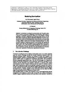
The data presented in Figure 9 is an initial comparison of the conciseness offered by DSLs like ECL. With reference to bytes of code, this figure visually represents the differences between ECL and the generated C++ code. The subjects of this study were a subset of several of the strategies that were created to support this research. An observation can be made regarding the State Generation strategy. Its translation yielded the lowest ratio of size comparison. This strategy also contains the least amount of ECL collection statements, suggesting the somewhat obvious observation that all of the code needed to iterate over a collection increases the amount of generated C++ code.
c = selectNode1; CComBSTR id0 = XMLParser::id(c);
ClData varforward1(id0); ClData varforward2(referredID); bool varforward3 = varforward1 == varforward2; if(varforward3) selectVecTrue1->push_back(*itrSelect1);
7000 6000 5000 4000 3000 2000 1000 0
ECL C++
}
n io at er e n on G e i ti s at n a St t Tr e en at zy St La ignm r/ ss n ge r A tio bu ri
i st D
o ss
er
itrCollCall1 != selectVecTrue1->end(); itrCollCall1++)
e oc
w
for(itrCollCall1 = selectVecTrue1->begin();
Ea
Pr
Po
vector::iterator itrCollCall1;
DetermineLaziness::apply(…);
…
Figure 9: Bytes of Code Comparison of ECL and C++
Figure 8: Sample of Generated C++ Code
Sensor
WCET=10ms
100 Hz
Latency < 2ms
Σ
WCET=4ms
WCET=1ms
Latency < 10ms
Latency < 20ms
Update Map (x,y,z)
(x,y,z) MapDB
(x,y,z)
Display
Weapon Release WCET=2ms Latency < 5ms
WCET=150ms
Figure 10: A Weapons Deployment Model
6. EXAMPLE We are using the Boeing BoldStroke framework as an experimental platform on some of our research efforts. Boeing’ s BoldStroke is a product-line framework for avionics navigation software [Sharp, 98]. In this section, an example strategy will be presented in a domain for modeling a subset of BoldStroke applications and configurations. Consider the diagram in Figure 10. This represents a simple model that contains five components. The first component is an inertial sensor. This sensor outputs, at a 100Hz rate, the position and velocity deltas of an aircraft. A second component is a position integrator. It computes the absolute position of the aircraft given the deltas received from the sensor. It must at least match the sensor rate such that there is no data loss. The weapon release component uses the absolute position to determine the time at which a weapon is to be deployed. It has a fixed period of 20Hz and a minimal latency requirement. A mapping component is responsible for obtaining visual location information based on the absolute position. A map must be constructed such that the current absolute position is at the center of the map. A fifth component is responsible for displaying the map on an output device. Notice the frequencies, latencies, and Worst Case Execution Times (WCET) of these components. The specific values of these properties will likely differ depending on the type of aircraft represented by the model (e.g., the latencies and WCETs for an F-18 would most likely be lower than a helicopter). The core modeling components describe a product family with the values for each property indicating the specific characteristics of a member of the family. Figure 11 provides a depiction of the weapons deployment model, represented within the GME. The model is an instance of the paradigm that was initially developed for the DARPA MOBIES
program, and later refined for a DARPA PCES project, to assist in the modeling of BoldStroke applications. The extensions that were made for PCES permit the representation of CORBA Component Models (CCM) [Siegel, 00]. The CCM provides capabilities that offer a greater level of reuse and flexibility for developers who need to deploy standardized components [Wang et al., 01].
Figure 11: A GME Model of the Component Interactions Each of the components in Figure 11 has internal details, in support of the CCM, that also are modeled. For instance, the contents of the Compute Position component are rendered in Figure 12. As can be noticed from the internals of this component, the series of interactions actually take place using a publish/subscribe model. The figure specifically highlights the attributes of a method called “ compute” (see the bottom-right of the figure). The attributes provide the name of the method, the
C++ source file that contains the method, and the method’ s estimated WCET.
WCETs of each component are accumulated. Whenever this accumulated value reaches past the threshold, a new processor is created for component assignment. Assign will finally call another strategy, named AddConstraint, which will add a new constraint to the model. The new constraint, in this case, represents the processor assignment. Admittedly, this particular strategy for processor assignment is very simple and would not be a best choice. However, it has been chosen for its simplification so that intricacies of the algorithm do not overshadow the intent of demonstrating the mechanism by which constraints are distributed. Also, observe that the entire strategy is written purely in ECL (except for one line of inlined code that is used for string creation).
defines AddConstraint, Assign, ProcessorAssignment;
strategy AddConstraint(constraintName, expression : string) { addAtom("OCLConstraint", "Constraint", constraintName).addAttribute("Expression", expression);
Figure 12: The Internals of Compute Position
}
strategy Assign(limit : integer)
6.1 Example Crosscutting Concern: Processor Assignment Suppose that we wanted to model the processor assignment of each component. That is, based upon the expected WCET, the component methods are executed as tasks on various processors. A notation is needed to specify the assignment of component methods/tasks to processors. One way to accomplish this representation issue is to specify the processor assignment as a constraint of the component model. The way that processor assignment is typically modeled involves the application of a set of heuristics that globally assign tasks to processors based on specific properties of each component. In modeling, this is often done by hand and requires the modeler to visit each component, or task, in order to manually apply the heuristic. For a model with a large number of components, this can be a daunting task. It becomes increasingly unmanageable in situations where the modeler would like to play “ what-if” scenarios. These “ what-if” scenarios are used to drive the iterative evolution of the model, such that intermediate scenarios may even be discarded. This is helpful because a modeler may want to change the values of different properties, or even modify the details of the heuristic, in order to observe the effect of different scenarios. A manual application of a heuristic would require that the modeler re-visit every component and re-apply the rules of the heuristic. An example of a specification aspect and strategy to support processor assignment can be found in Figure 13. The interpretation of the aspect called ProcessorAssignment is that an iteration is specified over all of the modeling elements that are of type “ Comp*” (note the use of the wildcard designator). The strategy, called Assign, is then invoked on each of these modeling components (here, a parameter bound to the value 10 represents a threshold of the execution time for each processor load). The purpose of the Assign strategy is to look into the “ compute” method of each component and find its WCET. The
{ declare static accumulateWCET, processNum : integer; declare currentWCET : integer;
self.compute.WCET.getInt(currentWCET); accumulateWCET := accumulateWCET + currentWCET;
if (limit < accumulateWCET) then accumulateWCET := currentWCET; processNum := processNum + 1; endif;
AddConstraint("ProcessConstraint", aConstraint); }
a)
Processor Assignment Strategy
aspect ProcessorAssignment { models("")->select(m | m.kind() = “Comp*”)->Assign(10); }
b) Specification Aspect for Component Processor Assignment Figure 13: Strategy/Aspect for Processor Assignment Note that the ProcessorAssignment aspect could be modified so that a different strategy is invoked (i.e., some strategy other than Assign); or, a different parameter threshold could be provided that may result in a different set of constraints (i.e., the parameter to Assign may be changed from 10 to 20). The key advantage of this approach is realized in the observation that,
from a change in one place, an entirely different set of constraints can be weaved. This solves a serious scalability problem concerning maintenance issues, and the ability to change the constraints within a model. Figure 14 shows the same component that was given in Figure 12. The only difference is that the component now contains a constraint that was added by the weaver as a result of applying the strategies described by the specification aspect. Notice that the strategy has assigned this component to processor 0. An examination of all the other components involved in this interaction would reveal that different components are assigned to processors based on their WCET and the parameterized threshold.
7.2 Applicability to Other Modeling Tools The previous sections assumed that the separation of modeling concerns was being performed on models created with the GME. In fact, this assumption is built into the XML Parser within the weaver framework. The limitation imposed by this assumption precludes other modeling tools (that also can export models using XML) from being able to employ the benefits of an aspect weaver. In addition to the GME, other examples of domain-specific visual modeling tools are Honeywell’ s Domain Modeling Environment [DOME], and metaEdit+ (from metaCASE) [Tolvanen and Kelly, 00]. It is possible that these, and other modeling tools (such as Ptolemy, from UC Berkeley [Lee, 01]), could benefit from an aspect-oriented modeling approach. A new code generator could be inserted into the weaver framework in order to provide an added measure of variability. From the modeling tool’ s Document Type Definition (DTD), the functionality of the wrappers provided within the XML Parser can be generated. This would permit adaptability of the framework between domains (using the strategy code generator), and also adaptability between modeling tools, using Generative Programming techniques [Czarnecki and Eisenecker, 00].
7.3 Aspect Modeling to Support OMG’s MDA
Figure 14: Component with Weaved Constraint
A future goal of our DARPA PCES project is to provide the capability for generating the configuration of BoldStroke components from domain-specific models in such a way that specific parts of each component are weaved together as an aspect. For example, a base model could capture the infrastructure of a product-line and constraints could represent specific configuration information for a particular product. A synthesis process could generate AspectJ components from an analysis of the model and constraints. This goal fits well with the OMG’ s Model Driven Architecture (MDA) [Bézivin, 01], as well as the idea of “ fluid AOP” [Kiczales, 01].
7. FUTURE WORK The ECL has truly been an evolving language – each new strategy that was created brought some fresh insight into additional language constructs that would be beneficial. In the future, the ECL will continue to evolve to support additional features (e.g., support for a “ cflow” or “ dflow” construct, similar to AspectJ). This section outlines some additional research objectives that will be explored in the immediate future.
7.1 Aspect Modeling as Visual Programming A potentially rewarding subject for future investigation will be the subsumption of the textual descriptions formulated within the ECL into a graphical modeling language; that is, an investigation into the expression of specification aspects, and even strategies, using a graphical formalism similar to that of visual programming languages. This kind of visual aspect modeling would, of course, be perfectly suited for exploration from within the GME. The concept of generating weavers from visual formalisms (i.e., interpreting strategy specifications that are described visually) is also appealing.
8. CONCLUSIONS A focal objective of the research described in this paper is to apply the concepts of aspect-oriented programming to domainspecific modeling. The implementation of this objective has resulted in a means for applying aspect modeling, per se, to the repertoire of a previously proven modeling tool (the GME). A contribution presented in the paper is a description of a language that has been used to support aspect modeling. As other work in this general area of aspect modeling has concentrated on important notational issues for extending the UML, the research here has brought the benefits of aspect-orientation to the modeling process itself. There are several reasons that would support the adoption of these ideas into a general modeling approach. As presented earlier, it was discovered on a previous DARPA project that a lack of support for separation of concerns with respect to constraints can pose a difficulty when creating domain-specific models. Constraints may be specified throughout the nodes of a model in order to stipulate design criteria and limit design alternatives. However, because these constraints are scattered across the hierarchy of a model, they are very difficult to change. The
scattering of constraints throughout various levels of a model makes it difficult to maintain and reason about their effects and purpose. The concept of a domain-specific weaver can be used in many ways beyond the application of constraints. The weaver can be used in order to distribute any system property (that is endemic to a specific domain) across the hierarchy of a model. A weaver can also be used to instrument structural changes within the model according to the dictates of some higher-level requirement that represents a crosscutting concern. To support the creation of weavers for numerous modeling domains, a metaweaver framework assists in the construction of new weavers. The framework, in conjunction with several code generators and DSLs, are used to provide the adaptability needed to construct new instances of the framework. A core component of this framework is a code generator that translates high-level descriptions of strategies into C++ source code. The conciseness of the ECL, compared to the generated code, provides a measure of the benefit for using DSLs to provide a higher level of abstraction.
9. ACKNOWLEDGMENTS We would like to thank the following individuals for comments on portions of this paper: Steve Schach, Gá bor Karsai, Janos Sztipanovits, Á kos Lédeczi, Mike Fitzpatrick, Fritz Barnes, and Larry Dowdy. Additionally, this work has benefited from previous general discussions with Gregor Kiczales, Rick Schantz, Joe Loyall, Craig Rodrigues, and David Sharp. We also thank Doug Schmidt for his support and helpful suggestions. This work is funded by the DARPA Information Technology Office (DARPA/ITO), under the Program Composition for Embedded Systems (PCES) program.
10. REFERENCES [AOSD, 02] http://aosd.net [Batory et al., 94] Don Batory, Jeff Thomas, and Marty Sirkin, “ Reengineering a Complex Application Using a Scalable Data Structure Compiler,” ACM SIGSOFT International Symposium on the Foundations of Software Engineering (FSE) , New Orleans, Louisiana, December 1994, pp. 111-120. [Bergmans and Aksit, 01] Lodewijk Bergmans and Mehmet Aksit, “ Composing Crosscutting Concerns using Composition Filters,” Communications of the ACM, October 2001, pp. 51-57. [Bézivin, 01] Jean Bézivin, “ From Object Composition to Model Transformation with the MDA,” Technology of Object-Oriented Languages and Systems (TOOLS), Santa Barbara, California, August 2001. [Clarke, 02] Siobhá n Clarke, “ Extending Standard UML with Model Composition Semantics,” Science of Computer Programming, May 2002.
[Clarke et al., 99] Siobhá n Clarke, William Harrison, Harold Ossher, and Peri Tarr, “ Subject-Oriented Design: Towards Improved Alignment of Requirements, Design, and Code,” Object-Oriented Programming, Systems, Languages, and Applications (OOPSLA), Denver, Colorado, November 1999, pp. 325-339. [Clarke and Walker, 01] Siobhá n Clarke and Robert J. Walker, “ Composition Patterns: An Approach to Designing Reusable Aspects,” International Conference on Software Engineering (ICSE), Toronto, Ontario, Canada, May 2001, pp. 5-14. [Clements and Northrop, 01] Paul Clements and Linda Northrop, Software Product Lines: Practices and Patterns, AddisonWesley, 2001. [Craig, 00] Iain Craig, The Interpretation of Object-Oriented Programming Languages, Springer-Verlag, 2000. [Czarnecki and Eisenecker, 00] Krzysztof Czarnecki and Ulrich Eiseneker, Generative Programming: Methods, Tools, and Applications, Addison-Wesley, 2000.
[DOME] http://www.htc.honeywell.com/dome/ [Filman and Friedman, 00] Robert Filman and Dan Friedman, “ Aspect-Oriented Programming is Quantification and Obliviousness,” OOPSLA Workshop on Advanced Separation of Concerns, Minneapolis, Minnesota, October 2000. [Gray et al., 01] Jeff Gray, Ted Bapty, Sandeep Neema, and James Tuck, “ Handling Crosscutting Constraints in Domain-Specific Modeling,” Communications of the ACM, October 2001, pp. 8793. [Gray, 02] Jeff Gray, “ Aspect-Oriented Domain-Specific Modeling: A Generative Approach Using a Metaweaver Framework,” Ph.D. Dissertation, Vanderbilt University, Department of Electrical Engineering and Computer Science, May 2002. [Hilliard, 99] Rich Hilliard, “ Views and Viewpoints in Software Systems Architecture,” First Working IFIP Conference on Software Architecture, San Antonio, Texas, 1999. [Ho et al., 02] Wai-Meng Ho, Jean-Marc Jezequel, Francois Pennaneac’ h, and Noel Plouzeau, “ A Toolkit for Weaving Aspect-Oriented UML Designs,” First International Conference on Aspect-Oriented Software Development, Enschede, The Netherlands, April 2002. [Hoffman and Weiss, 01] Daniel Hoffman and David Weiss, editors, Software Fundamentals – Collected Papers by David L. Parnas, Addison-Wesley, 2001. [Karsai and Gray, 00] Gá bor Karsai and Jeff Gray, “ Component Generation Technology for Semantic Tool Integration,” IEEE Aerospace Conference, Big Sky, Montana, March 2000. [Kiczales et al., 01] Gregor Kiczales, Eric Hilsdale, Jim Hugunin, Mik Kersten, Jeffrey Palm, and William Griswold, “ Getting Started with AspectJ,” Communications of the ACM, October 2001, pp. 59-65. [Kiczales, 01] Gregor Kiczales, “ Aspect-Oriented Programming: The Fun Has Just Begun,” Software Design and Productivity Coordinating Group – Workshop on New Visions for Software Design and Productivity: Research and Applications, Nashville, Tennessee, December 2001.
[Lédeczi et al., 01] Á kos Lédeczi, Arpad Bakay, Miklos Maroti, Peter Volgyesi, Greg Nordstrom, Jonathan Sprinkle, and Gá bor Karsai, “ Composing Domain-Specific Design Environments,” IEEE Computer, November 2001, pp. 44-51.
[Sharp, 98] David Sharp, “ Reducing Avionics Software Cost Through Component Based Product-Line Development,” Software Technology Conference, Salt Lake City, Utah, April 1998.
[Lee, 01] Edward Lee, “ Overview of the Ptolemy Project,” Technical Memorandum UCB/ERL M01/11, March 6, 2001.
[Siegel, 00] Jon Siegel, CORBA 3 Programming, John Wiley & Sons, 2000.
[Lieberherr et al., 01] Karl Lieberherr, Doug Orleans, and Johan Ovlinger, “ Aspect-Oriented Programming with Adaptive Methods,” Communications of the ACM, October 2001, pp. 3941.
[Sztipanovits and Karsai, 97] Janos Sztipanovits and Gá bor Karsai, “ Model-Integrated Computing,” IEEE Computer, April 1997, pp. 10-12.
[Long et al., 98] Earl Long, Amit Misra, and Janos Sztipanovits, “ Increasing Productivity at Saturn,” IEEE Computer, August 1998, pp. 35-43. [Neema, 01] Sandeep Neema, “ System Level Synthesis of Adaptive Computing Systems,” Ph.D. Dissertation, Vanderbilt University, Department of Electrical Engineering and Computer Science, May 2001. [Nordstrom et al., 99] Greg Nordstrom, Janos Sztipanovits, Gá bor Karsai, and Á kos Lédeczi, “ Metamodeling - Rapid Design and Evolution of Domain-Specific Modeling Environments,” International Conference on Engineering of Computer-Based Systems (ECBS), Nashville, Tennessee, April 1999, pp. 68-74. [Nuseibeh et al., 94] Basher Nuseibeh, Jeff Kramer, and Anthony Finkelstein, “ A Framework for Expressing the Relationship Between Multiple Views in Requirements Specification,” IEEE Transactions on Software Engineering, October 1994, pp. 760773. [Parnas, 72] David Parnas, “ On the Criteria To Be Used in Decomposing Systems into Modules,” Communications of the ACM, December 1972, pp. 1053-1058.
Fundamentals
and
[Tarr et al., 99] Peri Tarr, Harold Ossher, William Harrison, and Stanley Sutton, “ N Degrees of Separation: Multi-Dimensional Separation of Concerns,” International Conference on Software Engineering (ICSE), Los Angeles, California, May 1999, pp. 107119. [Tolvanen and Kelly, 00] Juha-Pekka Tolvanen and Steve Kelly, “ Visual Domain-Specific Modeling: Benefits and Experiences of Using metaCASE Tools,” ECOOP Workshop on Model Engineering, Cannes, France, June 2000. [Wang et al., 00] Nanbor Wang, Doug Schmidt, and Carlos O’ Ryan, “ Overview of the CORBA Component Model,” Component-Based Software Engineering: Putting the Pieces Together, George Heineman and William Councill, editors, Addison-Wesley, 2001. [Warmer and Kleppe, 99] Jos Warmer and Anneke Kleppe, The Object Constraint Language: Precise Modeling with UML, Addison-Wesley, 1999.