International Journal of Scientific & Engineering Research, Volume 7, Issue 5, May-2016 ISSN 2229-5518
ASSEMBLY BY PRESTRESSED OR HIGH-STRENGTH BOLT. CHAOUFI.ALI1 AHMED TAFRAOUI1 1
Laboratoire de Fiabilité du Génie Mécanique BP.417 Route de Kenadza 08000 Béchar, Algérie
Université tahri mohamed bechar algerie Email:
[email protected] E-mail :
[email protected]
Abstract: The analytical method provides a very good approximation of the tightening of a bolted assembly. Consequently, one can be satisfied with a fast analytical calculation to rather precisely check the tightening of a bolted assembly. A model finite element is hardly more precise at least of a point of considering total. One could still look further into these problems by determining in experiments the constraints in the screw and the part of a pre stressed bolted assembly. It would be also interesting to see more precisely, how evolves locally the constraints in the part and the screw. In this work, one learns how to quickly check the tightening of a pre stressed assembly bolted under static head. For that, one determines by an approach RDM the cons Keywords: Assembly pre stressed analyzes digital, constraints in the components of the assembly bolted.
IJSER
1.INTRODUCTION: What it is necessary to keep in mind: The simple design is to be searched in the choice of the devices of assemblies, this in order to have: Transmission of the more exact efforts Calculation more exact. Materials better utilizes. The checking of the assemblies is done while following the transmission of each effort in each part, the resistance of an assembly being that of its weakest point. One thus may find it beneficial to carry out the same degree of security for all the elements. The number and the importance of the assemblies on building site must be as reduced as possible, insofar as the assembly and transport conditions allow it. It cannot exist of regulation or handbook; however perfect is it, which gives to the designer the possibility of carrying out a drawing without the provided rules or indications being interpreted on the basis of the personal judgment, the professional experience and technical good sense of the designer.
Control of the deformations: the assemblies by bolts requested in traction have only rather weak deformations. On the other hand the assemblies by requested bolts perpendicular to their axes have more raised deformations because of the standardized games. One can however reduce these deformations by adopting gauged bolts or many pre stressed bolts. Dynamic stresses: the actions on the buildings are generally static, except in the event of presence of revolving machines, machines of handling, sieve, etc the vibrations can generate loosening of nuts or simply to harm the effectiveness of the bolted assemblies. One can in this case adopt devices of check nuts or assemblies by pre stressed bolts. In the same way the assemblies by pre stressed bolts are essential in the Low temperatures: it is advisable to use bolts profiting from a warranty of energy of minimal rupture during the crash test in inflection. Parasitic efforts in the assemblies: one must
IJSER © 2016 http://www.ijser.org
1855
International Journal of Scientific & Engineering Research, Volume 7, Issue 5, May-2016 ISSN 2229-5518
1856
take account of it case of seismic actions (where it is necessary to dissipate the energy of the jolts by the plastic deformations of the frame and the assemblies) and in the event of risk of ruin by tiredness. Figure4: assembly reinforced by sole. Figure1: assembly by simple covering. An assembly by simple covering creates one bending moment parasitizes and the assembly becomes deformed: It creates for itself parasitic internal efforts then:
Figure5: deformation of an assembly by traction. 2. Design of the assembly by bolt: From the point of view of construction, there are two basic methods of the design of an assembly per bolt: Assembly by bolt with pin A Assembly by bolt with nut B
IJSER
figure2: deformation of an assembly. The solution is to create symmetrical assemblies
Figure3: symmetrical assemblies. Additional moment of well aware of confusing neutral axis and axis of marking in the beams lattice: it is often the case when angles are used. In example Ci below the secondary moment is of 𝑀 = 𝐹2 − 𝐹1 𝑑…….1.1 Additional moment by action leverage: to avoid that Ci should be designed sufficiently rigid soles. If the soles are not rigid enough the bolts play the part of pivot, and one has a compressive force Q at the edges external of soles (effort of lever). By balance the traction effort in the bolts is worth: 𝐹𝑏 = 𝐹 + 𝑄………1.2
Figure
6:
Assembly
by
bolt.
2.1 Load of the assembly by bolt: According to the type of load, an assembly by pre stressed bolt must answer the various requirements; this has like consequence a different method of calculating of the pre stressing of assembly. There are three various types of load for calculations of the assemblies by bolt: Load in line with bolt: The assembly by bolt is under the action of the thrust load F. Here the pre stressing of assembly ensures compactness or more precisely, the sealing of the assembly during operation. The pre stressing of the assembly must thus be enough high to ensure a sufficient residual pre stressing of the part connected after the constraint of the assembly by the active force and thus the link of force
IJSER © 2016 http://www.ijser.org
International Journal of Scientific & Engineering Research, Volume 7, Issue 5, May-2016 ISSN 2229-5518
necessary between surfaces of contact. Load perpendicular to the axis of the bolt: The assembly by bolt is under the action of the radial force Fr, acting in the plan of the parts connected. The pre stressing of assembly ensures the load capacity of shearing of the assembly using the forces of friction. The transverse force acting on the assembly must thus be transferred between the parts connected by the friction, which is due to the pre stressing of tightening of the bolts. Load combined: The assemblies being due to a combined load
not have any meaning for the type chosen, will be hidden. 3. Automatic design of the bolt: In software SOLIDWORKS one will make the manual design as one can open the library of the SOLIDWORK which one goes selected among the types of bolts this choice and called automatic design; from the toolbox SOLIDWORKS with the selected ISO standard one among the types according to: - bolt with square collars - bolt with cruciform print - cap screw set split - bolt auto—drilling machines - bolt CHC - bolt hexagonal - bolt hexagonal with fine step - bolt without head 6hollow sides - bolt without split head And here is an example (figure) which we applied has our simulation.
IJSER
Figure7: Various types of load for calculations of the assemblies by bolt. 2.2 Type of the load: This list makes it possible to the users to define the type of the load which acts on the assembly. The assembly by bolt can be conceived for the following types of load: A- Silencer (static). B- With pulsation. C- Passage. D- AlterNet asymmetrical. E- Alternated symmetrical.
Figure 8: Type of the load which acts on the assembly. F- With the assemblies due to a cyclic load (load B with…) it is also necessary to carry out, besides the current strength checks, controls of the bolt by the strength of tiredness. G- Choose the desired type of the load. After choice, calculation will be modified in configuration which corresponds to the selected type of load the parameters, which do
Figure 9: bolt hexagonal ISO 4162 – M8. 50. 22-N 3.1 .type of study: In the machine analysis there is several type of studies like continuation: Statics Frequency Buckling Thermal Test of fall Tiredness Nonlinear statics Linear dynamics Design of a device under pressure With our case of study we chose the linear static study. 3.2. Linear static analysis When a loading is applied to a body, this one becomes deformed and the effects of the loading are transmitted in all the body. The external forces induce internal forces and reactions which lead the body to a state of
IJSER © 2016 http://www.ijser.org
1857
International Journal of Scientific & Engineering Research, Volume 7, Issue 5, May-2016 ISSN 2229-5518
balance. The linear static analysis calculates displacements, the strains, the stresses and the forces of reaction under the effect of the loadings applied. Assumption of staticity: All the loadings are applied slowly and gradually until the desired intensity. Once this intensity reached, the loadings remain constant in time. This assumption enables us to neglect the effects of the inertial forces and damping, because induced speeds and accelerations are negligible. A variable loading in the time, which would induce inertial forces and/or of damping considerable, could justify a dynamic analysis. The dynamic loadings vary in time and, in many cases, induce inertial forces and of damping important, which cannot be neglected. Assumption of linearity. The relation between the loadings and the induced answers is linear. If you double for example the intensity of the loading, the answer of the model (displacements, strains and stresses), will be doubled. You can apply the assumption of linearity if: All the materials used in the model check the law of Hooke, i.e. the calculated constraint is directly proportional to the deformation. Induced displacements are sufficiently small to be unaware of the changes generated by the loading on the matrix of stiffness. The boundary conditions do not vary during the application of the loading. The loading must be constant in time in intensity, direction and distribution. It should not change under the effect of the deformation of the model.
Figure11:
1858
choice of
3.4. Displacement imposed: For volumes, this kind of imposed displacement defines all the degrees of freedom of translation in zero. For the bolts, it defines the degrees of freedom of translation and rotation in zero. For connections of bars, it defines the degrees of freedom of translation in zero. When one uses in this type imposed displacement, no geometry of reference is necessary.
IJSER
Figure 10: linear static study 3.3. Choice of material: Before carrying out a study of analysis, one will define all the material properties necessary to the corresponding type of analysis. For example, the modulus of elasticity is necessary for the static studies, for our example one will choose the steel alloy. (Figure11).
material.
Figure12:
fixed geometry.
3.5. Force applied or couples applied: a) Force/Torque: Application of the forces, the moments or the couples presenting a uniform distribution on the faces, edges, points of reference, tops and beams in any managerial staff, the executive staff of structural studies. The specified force is applied to each selected top, edge, face or beam. When we apply a force to a face or an edge, the value specifies represents only the amplitude. Thus, if we apply a normal force to an entirely cylindrical face, the vector sum of the forces applied is worthless. We can apply non uniform forces to the faces, edges of hulls and beams. A non uniform force is defined by a value and a distribution. The value of the force is equal to the sum of all the absolute values of the forces applied to each face. The distribution of the force is described by the coefficients of a polynomial of the 2nd degree according to axes X and Y of the frame of reference of reference, as described for the variable pressure.
IJSER © 2016 http://www.ijser.org
International Journal of Scientific & Engineering Research, Volume 7, Issue 5, May-2016 ISSN 2229-5518
Figure15: Figure 13: application of the loads on the bolt. 3.6.le grid: During the grid of a part or one assembly using volume elements, the software generates one of the following types of elements, according to the active options of grid for the study: · Grid average quality. The automatic mesh generates volume linear tetrahedral elements. · Grid top quality. The automatic mesh generates volume parabolic tetrahedral elements. The linear elements are also called first order elements or of a lower nature. The parabolic elements are also called elements of the second order or a higher nature. A linear tetrahedral element is defined by 4 nodes in the tops and 6 right edges which connect them. A parabolic tetrahedral element is defined by 4 nodes in the median tops, 6 nodes and 6 edges. A schematized representation of the linear and parabolic tetrahedral elements volume is given in the following figures
1859
linear mesh
3.7. Design and geometry of the bolt: Sometimes it is suitable, from the technological point of view or construction, to use a special bolt in the assembly instead of an ordinary prismatic bolt with various cross sections. For example where necessary of a precise assembly of the parts using the adapted bolts or using a bolt connected to a stem shortened to reduce the influence of the additional bending stresses. Flexible bolts with a special treatment are also frequently used for the assemblies exposed to a variable load.
IJSER
Figure 14: choice of elements for grid. For the structural problems, each node of a volume element has 3 degrees of freedom representing the translations in the three orthogonal directions of space. The software uses directions X, Y and Z of the total Cartesian frame of reference to formulate the problem (figure 15).
Figure 16:
bolt
with shortened
stem.
4. Design of surfaces of contact under the heads (nuts) of the bolts: For the assemblies by bolt, three types of basic designs of surfaces of contact below heads (nuts) of the bolts are used. A- Circular surface of contact: The most normal case more running and for the contact in the assemblies by bolt with normal nuts if surfaces of contact are perpendicular to the axis of the bolt. BConical surface of contact: Special use for the assemblies by bolt where the precise centering of the part connected against the axis of the bolt is required. This requires a special conical nut and a conical seat in the hole for the bolt, consequently a greater requirement of precision in the production. C- Spherical surface of contact.
IJSER © 2016 http://www.ijser.org
International Journal of Scientific & Engineering Research, Volume 7, Issue 5, May-2016 ISSN 2229-5518
Figure 17: Different contact surfaces. Special use in the assemblies where the perpendicularity of surfaces of contact to the axis of the bolt and consequently its additional bending strain can be envisaged. This requires a special ball nut and a spherical seat in the hole for the bolt. What is very demanding for the technology of production? 4.1. Pre stressed , power struggles and operational diagram of the assembly: In this paragraph we can find the power struggles acting in the assembly by designed pre stressed bolt. The power struggle in an assembly by bolt entirely in charge for pre stressing of support given is calculated in the last part. The power struggles are illustrated in the image in the lower part of this paragraph.
1860
Table1: Model Information Name of document reference
the and
Treaty like
Volumetric properties
Volume body
Mass: 0.0172446 lb Volume: 0.0619907 in^3 Density: 0.27818 lb/in^3 Weight: 0.0172329 lbf Mass: 0.0586841 lb Volume: 0.210957 in^3 Density: 0.27818 lb/in^3 Weight: 0.0586443 lbf
EndChamfer
Volume body
FlangeHexFillet
Table2:
Properties
of
the
Name of study Type of analysis Type of grid Heating effects: Thermal option
Study 2 Statics Volume grid Activated (E) To include loadings
Temperature of worthless deformation
25 Centigrade
To include the pressure of the fluid Calculated by Solid Works Flow Simulation
Disabled (E)
Type
FFE More
IJSER
Figure 18: Assembly bolt screw nut.
a) Assumptions: SCREW fix. · Touch · Tightening applied between face FEMALE SCREW. · Force applied to the threaded body. b) Information on the model:
figure19: Name of the model: Assemblage1 Current configuration: Assembly bolt screw nut
of
solvor
Stiffening stress:
Disabled (E)
Low stiffness:
Disabled (E)
Inertial relieving:
Disabled
Options of incompatible interdependent contact
Automatic
Great
Disabled (E)
displacement
To check the external forces
Activated (E)
Friction
Disabled(E)
Adaptive method:
Disabled (E)
IJSER © 2016 http://www.ijser.org
study:
thermal
(E)
International Journal of Scientific & Engineering Research, Volume 7, Issue 5, May-2016 ISSN 2229-5518
Table3:
Units
System of units: Length/Displacement Temperature Angular velocity Forced /pressure
Table4: Properties Reference the model
of
1861
Fixed-1 IF (MKS) mm Centigrade rad/ Dry N/m^2
of
material:
Properties
Components
Name: Steel alloy Type of model: Linear isotropic rubber band Criterion of ruin by default: Constraint of max.von Mises Elastic limit: 6.20422e+008 N/m^2
Volume body 1 (End Chamfer) (Hexagon Flange Nut ISO - 4161 M8 N-1), volume Body 1 (Flange Hex Fillet) (ISO 4162 - M8 X 50 X 22N-1)
Entities: 1face (S) Type: Fixed geometry
Table6: Resulting forces Compone X Y nts Force of 1572. 0.000143 reaction 51 83 (NR) Moment 0 0 of reaction (Nm) Table7: loading Force Name of the Image of loading loading
the
IJSER
Data
of
the
Table5: External Name displacement imposes
of
curve:
Information
on
Image of contact
Contact between whole1
Total contact
Table9:
N/A
actions: Image of imposed displacement
Details of imposed displacement
Information
Type of grid Mesh used: Points of Jacobien Size of maximum element Size of minimum element Quality of grid To re-mesh the parts in failure with an incompatible grid
IJSER © 2016 http://www.ijser.org
Resulta nt 1572.5 1 0
Details of the loading Entity:1face (S) Type: Normal force Value:500000N
Contact
Modulus of elasticity: 2.1e+011 N/m^2 Poisson's ratio: 0.28 Density: 7700 kg/m^3 Modulus of rigidity: 7.9e+010 N/m^2 Thermal dilation coefficient: 1.3e-005 /Kelvin
.001080 89 0
Force-1
Table8:
Limit of traction: 7.23826e+008 N/m^2
Z
the
the
contact:
Properties of the contact Type: Contact between pair tight adjustment Entities:3face (S) Advanced: Surface on surface Type: Inter dependent Components:1 component (S) Options: Compatible mesh
on
mesh:
Volume grid Grid based on the curve With the nodes 3.29658 mm 0.659317 mm High Disabled (E)
International Journal of Scientific & Engineering Research, Volume 7, Issue 5, May-2016 ISSN 2229-5518
1862
Table10: Information on mesh – Details:
Table14: displacement
Full number of nodes Full number of elements Maximum aspect ratio % of elements having an aspect ratio < 3 % of elements having an aspect ratio > 10 % of distorted elements (Jacobien):
Name Déplacements1
Table11: Resulting Forces of Together of selections Entier model
22825 13905 81.485 93.4
Max 0.0551651mm Node: 22260
0
forces: reaction:
Sum X
Sum Y
Sum Z
resulting
N
1572.51
0.00014383
0.00108089
1572.51
Figure21 : Assembly 1- Study 2- Diplacements Diplacements 1
Table15 : Déformations Name Déformations1
Type ESTRN: Equivalent deformation
Min 0 Element: 1
IJSER
Table12:
Moments
Together of selections Entier model
Units
Sum X
N.m
0
Name Contraintes1
Min 0 mm Node: 1
0.813
Units
Table13: Contraintes
Type URES: resulting displacement
Type VON: constraint of Von Mises
of
reaction:
Sum Y
Sum Z
resulting
0
0
0
Min 0 N/m^2 Node: 1
Max 0.00182335 Element: 12191
Max 4.97941e+008 N/m^2 Node: 13613
Figure22 : Assembly 1- Study 2- Déformations Déformations1
Figure2 : Assembly 1- Study 2- constraint- constraints1
Conclusion: For a loading of 500000 NR one notes that the value of the constraint reaches a maximum value of 4x10+8 N/m2 and then will fall towards a minimal value of 0.5x10+8N/m2ce which implies that this assembly does not resist the maximum value. For this the displacement reaches the maximum value of 0.045mm. And with the node #13708 there is a deformation which reaches the maximum value and then will fall up to zero. What gives a contracting of the diameter of the Screw and the nut will slightly move what localization of
IJSER © 2016 http://www.ijser.org
International Journal of Scientific & Engineering Research, Volume 7, Issue 5, May-2016 ISSN 2229-5518
game
between
the
parts
means [11]
Reference [1]
[2]
[3]
[4]
[5]
[6]
[7]
[8]
[9]
[10]
bibliography
Bibliography on Bolted and Riveted Joints, ASCE Manuals and Reports on Engineering Practice, No. 48, American Society of Civil Engineers, Reston, VA., Bibliography on Riveted Joints, A.E.R. deJong, American Society of Mechanical Engineers, New York, 1945. C. Batho and E.H. Bateman, ―Investigations on Bolts and Bolted Joints, Second Report of the Steel Structures Research Committee,‖ London, 1934. W.M. Wilson and F.P. Thomas, ―Fatigue Tests on Riveted Joints,‖ Bulletin 302, Engineering Experiment Station, University of Illinois, Urbana, 1938. Research Council on Riveted and Bolted Structural Joints of the Engineering Foundation, Specifications for Assembly of Structural Joints Using High-Strength Bolts, 1951. G.L. Kulak, J.W. Fisher, and J.A.H. Struik, ―Guide to Design Criteria for Bolted and Riveted Joints,‖ Second Edition, John Wiley, New York, 1987. Connections in Steel Structures: Behaviour, Strength, and Design, Elsevier Applied Science, 1988, Editors: Reidar Bjorhovde, Jacques Brozzetti, and Andre Colson Connections in Steel Structures II: Behavior, Strength, and Design, American Institute of Steel Construction, 1991. Editors: Reidar Bjorhovde, Andre Colson, Geerhard Haaijer, and Jan Stark. Connections in Steel Structures III: Behaviour, Strength, and Design, Pergamon, 1996. Editors: Reidar Bjorhovde, Andre Colson, and Riccardo Zandonini. Connections in Steel Structures IV: Behavior, Strength and Design, American Institute of Steel
[12]
[13]
[14]
1863
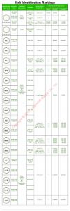
Construction, 2002. Editors: R. T. Leon and W.S. Easterling. ASTM A502-93, Standard Specification for Steel Structural Rivets, American Society for Testing and Materials, West Conshohocken, Pennsylvania, USA. ASTM A307-00, Standard Specification for Carbon Steel Bolts and Studs, 60 000 PSI Tensile Strength, American Society for Testing and Materials, West Conshohocken, Pennsylvania, USA. ASTM A325-02, Standard Specification for Structural Bolts, Steel, Heat Treated, 102/105 ksi Minimum Tensile Strength, American Society for Testing and Materials,West Conshohocken, Pennsylvania, USA. ASTM A490-02, Standard Specification for Structural Bolts, Alloy Steel, Heat-Treated, 150 ksi Minimum Tensile Strength, American Society for Testing and Materials,West Conshohocken, Pennsylvania, USA. Load and Resistance Factor Design Specification for Structural Joints Using ASTM A325 or A490 Bolts, Research Council on Structural Connections, 2000.(Available free at www.boltcouncil.org). ASTM A563-00, Standard Specification for Carbon and Alloy Steel Nuts, American Society for Testing and Materials,West Conshohocken, Pennsylvania, USA. ASTM F436-93(2000), Standard Specification for Hardened Steel Washers, American Society for Testing and Materials,West Conshohocken, Pennsylvania, USA. Association canadienne de normalisation, CAN/ CSA–S16–01 Limit States Design of Steel Structures, Toronto, 2001. G.L. Kulak and G.Y. Grondin, Limit States Design in Structural Steel, Seventh Edition, Canadian Institute of Steel Construction, Toronto, 2002. Association canadienne de normalisation, CAN/ CSA–S6–00 Code canadien sur le calcul des ponts routiers, Toronto, 2000.
IJSER [15]
[16]
[17]
[18]
[19]
[20]
IJSER © 2016 http://www.ijser.org
International Journal of Scientific & Engineering Research, Volume 7, Issue 5, May-2016 ISSN 2229-5518
[21]
[22]
[23]
[24]
[25]
[26]
[27]
[28]
[29]
[30]
[31]
L. Shenker, C.G. Salmon, and B.G. Johnston, ―Structural Steel Connections,‖ Department of Civil Engineering, University of Michigan, Ann Arbor, 1954. Fisher, J.W., Galambos, T.V., Kulak, G.L., and Ravindra, M.K., ―Load and Resistance Factor Design Criteria for Connectors,‖ J. of the Structural Division, ASCE, Vol. 104, No. ST9, September 1978. Munse, W.H. and Cox, H.C., ―The Static Strength of Rivets Subjected to Combined Tension and Shear,‖ Engineering Experiment Station Bulletin 427, University of Illinois, Urbana, 1956. Hechtman, R.A., ―A Study of the Effects of Heating and Driving Conditions on Hot-Driven Structural Steel Rivets,‖ Department of Civil Engineering, University of Illinois, Urbana, 1948. Yoshida, N. and Fisher, J.W., ―Large Shingle Splices that Simulate Bridge Joints,‖ Fritz Engineering Laboratory Report No. 340.2, Lehigh University, Bethlehem, PA, December, 1968. Rumpf, John L. and Fisher, John W., ―Calibration of A325 Bolts,‖ J. of the Structural Division, ASCE, Vol. 89, ST6, December, 1963. Christopher, R.J., Kulak, G.L., and Fisher, J.W., ―Calibration of Alloy Steel Bolts,‖ J. of the Structural Division, ASCE, Vol. 92, ST2, April, 1966. Bickford, John H., ―An Introduction to the Design and Behavior of Bolted Joints,‖ Second Edition, Marcel Dekker Inc., New York, 1990. Kulak, G.L. and Birkemoe, P.C., ―Field Studies of Bolt Pretension,‖ J. Construct. Steel Research, Vol. 25, Nos. 1 & 2, pages 95-106, 1993. ASTM F1852-00, Standard Specification for ―Twist Off‖ Type Tension Control Structural Bolt/Nut/Washer Assemblies, Steel, Heat Treated, 120/105 ksi Minimum Tensile Strength, American Society for Testing and Materials,West Conshohocken, Pennsylvania, USA. Kulak, Geoffrey L. and Undershute, Scott T., ―Tension Control Bolts:
[32]
[33]
[34]
Strength and Installation,‖ Journal of Bridge Engineering, Vol. 3 No. 1, ASCE, February, 1998. ASTM F959–99a, Standard Specification for CompressibleWasher-Type Direct Tension Indicators for Use with Structural Fasteners, American Society for Testing and Materials, West Conshohocken, Pennsylvania, USA. Dahl, Joan S., Le-Wu Lu, Fisher, John W., and Abruzzo, John, ―Comparative Effectiveness of Tightening Techniques for A490 1-1/4 in. Diameter Bolts,‖ Engineering Journal, American Institute of Steel Construction, Vol. 33, No. 1, First Quarter, 1996. Oswald, C.J., Dexter, R.J., Brauer, S.K., ―Field Study of Pretension in Large Diameter A490 Bolts,‖ ASCE Journal of Bridge Engineering, Vol. 1, August, 1996. Mikkel A. Hansen, ―Influence of Undeveloped fillers on Shear Strength of Bolted Splice Joints,‖ PSFSEL Thesis No. 80–1, Department of Civil Engineering, The University of Texas at Austin, March, 1980. Yura, J.A., Frank, K.H., and Polyzois, D., ―High Strength Bolts for Bridges,‖ PMFSEL Report No. 87–3, Department of Civil Engineering, The University of Texas at Austin, May, 1987. Load and Resistance Design Specification for Structural Steel Buildings, American Institute of Steel Construction, Chicago, Illinois, 1999. Chesson, Eugene, Jr., Munse,William H., and Faustino, Norberto R., ―HighStrength Bolts Subjected to Tension and Shear,‖ Journal of the Structural Division, ASCE, Vol. 91, ST5, October, 1965. Chesson, Eugene, Jr., ―Bolted Bridge Behavior During Erection and Service,‖ Journal of the Structural Division, ASCE, Vol. 91, ST3, June, 1965. Kulak, Geoffrey L. and Grondin, G.Y., ―AISC LRFD Rules for Block Shear in Bolted Connections—A Review,‖ Engineering Journal, American Institute of
IJSER [35]
[36]
[37]
[38]
[39]
[40]
IJSER © 2016 http://www.ijser.org
1864
International Journal of Scientific & Engineering Research, Volume 7, Issue 5, May-2016 ISSN 2229-5518
[41]
[42]
[43]
[44]
[45]
[46]
[47]
[48]
[49]
[50]
[51]
Steel Construction,Vol. 38, No. 4, Fourth Quarter, 2001. (Voir aussi les errata à cette référence.) Driver, R.G, Grondin, G.Y., and Kulak, G.L., ―A Unified Approach to Design for Block Shear,‖ Proc. Connections in Steel Structures V, Amsterdam, June, 2004. Munse,W.H. and Chesson, E. Jr., ―Riveted and Bolted Joints: Net Section Design,‖ J. of the Struct. Div., ASCE, Vol. 89 (1),. 107–126,1963. Chesson, E., Jr., and Munse,W.H., ―Riveted and Bolted Joints: Truss Type Tensile Connections,‖ J. of the Struct. Div., ASCE, Vol. 89 (1), 67– 106, 1963. McGuire, William, ―Steel Structures,‖ Prentice-Hall Inc., Englewood Cliffs, N.J., 1968. Institut canadien de la construction en acier, ―Handbook of Steel Construction,‖ Eighth Edition, Willowdale, Ontario, 2004. Fisher, J.W., Kulak, G.L., and Smith, I.F.C., ―A Fatigue Primer for Structural Engineers,‖ National Steel Bridge Alliance, American Institute of Steel Construction; Chicago, IL., 1998. Fisher, J.W.,Yen, B.T. and Wang D., ―Fatigue of Bridge Structures – a Commentary and Guide for Design, Evaluation and Investigation Of Cracking,‖ ATLSS Report No 89-02, Lehigh University, Bethlehem, PA, 1989. Kulak, G.L., ―Fatigue Strength of Riveted Shear Splices,‖ Progress in Structural Engineering and Materials, Vol 2 (1), 1–10, 2000. Dexter, J. Robert, Wright, W.J., and Fisher, J.W., ―Fatigue and Fracture of Steel Girders,‖ J. of Bridge Engineering, ASCE, Vol. 9, No. 3, May, 2004. Josi, Georg, Grondin, Gilbert Y., and Kulak, Geoffrey L. ―Fatigue of Joints with Staggered Holes,‖ Journal of Bridge Engineering,Vol. 9, No. 6, November–December 2004. American Association of State Highway and Transportation Officials, ―AASHTO LRFD Bridge Design
[52]
[53]
[54]
[55]
[56]
Specifications, SI, 3rd Edition,‖ Washington, D.C., 2004. Nair, R.S., Birkemoe, P.C., and Munse, W.H., ―High Strength Bolts Subjected to Tension and Prying,‖ J. of the Structural Division, ASCE, Vol. 100, No. ST2, February, 1974. Bouwman, L.P., ―Fatigue of Bolted Connections and Bolts Loaded in Tension,‖ Report No. 6–79–9, Stevin Laboratory, Delft Univ. of Technology, Delft, The Netherlands, 1979. Structural Bolting Handbook, Steel Structures Technology Center, Inc. Novi, MI., 2000. Manuel, Thomas J. and Kulak, Geoffrey L., ―Strength of Joints that Combine Bolts and Welds,‖ Journal of Structural Engineering, ASCE, Vol. 126, No. 3, March, 2000. Kulak, Geoffrey L. and Grondin, G.Y., ―Strength of Joints that Combine Bolts and Welds,‖ Engineering Journal, American Institute of Steel
IJSER
IJSER © 2016 http://www.ijser.org
Construction, Vol. 40, No. 2, Second Quarter 2003.
1865


![PRESTRESSED CONCRETE PIPES [PSC]](https://m.moam.info/img/260x300/prestressed-concrete-pipes-psc_5993ec731723ddd169543a1e.jpg)


