from an external wound to another external wound, a bullet lodged in the body, or a skeletal nick. ... The smaller base of the frustum is positioned at the blade's.
Assessing the Involvement of Anatomical Structures in Penetrating Trauma Probabilistically Omolola Ogunyemi Center for Human Modeling and Simulation Department of Computer and Information Science Univ. of Pennsylvania, Philadelphia, PA 19104{6389 April 1997
Abstract To determine the type and magnitude of injuries involved in penetrating trauma from gunshot and stab wounds, a working knowledge of the relationship between human anatomy, physiology, and physical manifestations of injury is required. With ballistic injuries involving multiple entry and exit wounds, determining the extent and type of injuries is made even more di�cult as many di�erent trajectories could produce the same external wounds. This work presents a 3D graphical system that allows the user to visualize di�erent bullet path hypotheses as well as stab wound paths in a 3D model of the human body, and to identify the anatomical structures a�ected for each path. The system also presents the degree of belief that an anatomical structure associated with a given penetration path is injured, expressed as a probability. It is designed to work both with TraumAID (a system for providing decision support in the initial de nitive management of trauma) and MediSim (a system that simulates casualties, medics and interactions between them).
i
Acknowledgements The author would like to thank the following people whose insightful suggestions, questions, comments (and code in some cases) helped shape this work: Dr. Clarke, Dr. Webber, Jonathan Kaye, Rich Washington, Harold Sun, Brett Achorn, Dr. Abba Krieger, and Welton Beckett. This work has been supported by the National Library of Medicine under contract number NO1-LM-4-3515, and ARPA under grant number DAMD17-94-J-4486.
ii
Contents Abstract Acknowledgements List of Figures List of Tables 1 Introduction
i ii v vi 1
2 Anatomical and Geometric Models
3
1.1 Penetration Path Assessment System Overview : : : : : : : : : : : : 2.1 2.2 2.3 2.4
De nitions : : : : : : : : : : : : Representation of Anatomy : : Gunshot wound representation : Stab wound representation : : :
: : : :
: : : :
: : : :
: : : :
: : : :
: : : :
: : : :
: : : :
: : : :
: : : :
: : : :
: : : :
: : : :
: : : :
: : : :
: : : :
: : : :
: : : :
: : : :
: : : :
: : : :
3 Injury Generation and Assessment
Introduction and De nitions : : : : : : : : : : : : : : : : : : : : : : : Generating penetration path hypotheses : : : : : : : : : : : : : : : : Performing penetration analysis : : : : : : : : : : : : : : : : : : : : : Calculating injury probabilities : : : : : : : : : : : : : : : : : : : : : 3.4.1 Generating experimental bullet trajectories : : : : : : : : : : : 3.4.2 Generating experimental stab paths : : : : : : : : : : : : : : : 3.4.3 Examples: Estimating hit probabilities : : : : : : : : : : : : : 3.4.4 Determining overall hit probabilities for anatomical structures 3.5 `Interactive' example : : : : : : : : : : : : : : : : : : : : : : : : : : :
3.1 3.2 3.3 3.4
4 The User Interface
4.1 Overview : : : : : : : : : : : : : : : : : : : 4.2 System Input : : : : : : : : : : : : : : : : 4.2.1 Wound placement : : : : : : : : : : 4.2.2 Bullet and skeletal nick placement : 4.3 System Output : : : : : : : : : : : : : : : iii
: : : : :
: : : : :
: : : : :
: : : : :
: : : : :
: : : : :
: : : : :
: : : : :
: : : : :
: : : : :
: : : : :
: : : : :
: : : : :
: : : : :
: : : : :
1
3 3 4 5
6
6 7 9 11 12 14 14 15 17
23 23 25 26 26 26
5 Applications
27
6 Future Work
30
5.1 TraumAID : : : : : : : : : : : : : : : : : : : : : : : : : : : : : : : : : 5.2 MediSim : : : : : : : : : : : : : : : : : : : : : : : : : : : : : : : : : : 5.3 Educational : : : : : : : : : : : : : : : : : : : : : : : : : : : : : : : :
6.1 Improvements to anatomical and wound path space models : 6.1.1 Body Type : : : : : : : : : : : : : : : : : : : : : : : 6.1.2 Anatomical Structure Representation : : : : : : : : : 6.1.3 Stab path treatment : : : : : : : : : : : : : : : : : : 6.2 Constraining the penetration path hypotheses : : : : : : : : 6.3 User Interface : : : : : : : : : : : : : : : : : : : : : : : : : :
7 Conclusion A Changing the Variance Bibliography
: : : : : :
: : : : : :
: : : : : :
: : : : : :
: : : : : :
27 28 28
30 30 30 31 31 31
32 33 38
iv
List of Figures 2.1 2.2 3.1 3.2 3.3 3.4 3.5 4.1
3D gunshot wound path space and a 2D circle section : : : : : : : : : Stab wound path space : : : : : : : : : : : : : : : : : : : : : : : : : : Three penetration path hypotheses for two through wounds : : : : : : Bounding box for the polygonal surface representation of a diaphragm Stab and gunshot wound path space cross-sections : : : : : : : : : : : Overhead views of three penetration path hypotheses : : : : : : : : : Penetration path hypothesis with injury probabilities : : : : : : : : : Penetration path assessment system torso model : : : : : : : : : : : :
v
4 5 7 10 13 18 22 25
List of Tables 3.1 Hypotheses given i wounds and b bullets : : : : : : : : : : : : : : : : 3.2 Hypotheses given i gunshot wounds : : : : : : : : : : : : : : : : : : : 4.1 Menu structure for penetration path assessment system : : : : : : : :
vi
8 9 24
Chapter 1 Introduction Penetrating trauma is responsible for a large proportion of civilian deaths in the United States and is a major cause of battle eld fatalities. There is evidence that early administration of expert care to victims of penetrating trauma would considerably reduce the number of deaths due to these injuries [36]. In dealing with penetrating injuries, physicians are generally concerned about the anatomical structures a�ected, as the types of injuries to vital structures could determine a patient's treatment and chances for survival. Determining the extent of injuries is made di�cult in the case of multiple gunshot wounds because many di�erent pairings are possible for entry wounds to exit wounds or entry wounds to bullets lodged in the body. In this work, we present a 3D graphical penetration path assessment system that enables users to visualize di�erent bullet path hypotheses and stab wound paths, using a rotatable 3D model of the human torso. The system identi es the anatomical structures a�ected for each path and presents the degree of belief that an anatomical structure associated with a given penetration path is injured, expressed as a probability (within con dence limits). By displaying 3D models of gunshot and stab wound paths and injured organ possibilities for a given set of wounds, the system provides a visual cue to their potential consequences; a kind of virtual CT-scan. This can help in bridging the gap between knowledge of the anatomy involved in a particular injury and the physiological manifestations associated with that injury.
1.1 Penetration Path Assessment System Overview The penetration path assessment system is based on Leonard Karpf's ideas about model based penetration path calculations [23]. It extends this work by providing a graphical user interface with a 3D torso model on which injuries can be simulated, di�erent injury hypotheses generated and assessed probabilistically, and by presenting the user with both visual (graphical) and written feedback about injury assessments. Probabilities generated by the system make the feedback more precise by quantifying the likelihood of damage to a�ected structures. 1
In assessing gunshot wounds, the goal of the system is to present an initial space of penetration possibilities , and so ballistic characteristics such as bullet type and velocity are not considered in assessing injuries. Although the system can assess the e�ect of bullet ricochet o� skeletal parts, issues such as bullet fragmentation and the impact of secondary projectiles from bullet or bone fragments are not addressed within the system. For an examination of these and other related issues, see [15, 16, 17, 18, 33, 37]. 1
The focus of the current penetration path assessment system has been on addressing penetrating injuries to the chest and abdomen, as some of the most life-threatening penetrating injuries a�ect these regions. We believe that a more uniform treatment of penetrating injuries to di�erent areas of the body would be desirable and so we plan to extend the system to deal with injuries to the limbs and head.
Note that penetration possibilities (i.e., the possibility of damage to particular anatomical structures) combined with signs and symptoms observed in a patient determine injury possibilities. For example, lung puncture accompanied by the appropriate signs and symptoms in a patient might lead to a diagnosis of tension pneumothorax, simple pneumothorax or both. 1
2
Chapter 2 Anatomical and Geometric Models 2.1 De nitions The penetration path system determines possible involvement of anatomical structures in multiple penetrating injuries using 3D models of wound paths and anatomical structures. We refer to the three-dimensional models of wound paths as wound path spaces. For gunshot wounds, a wound path space is the space of possible trajectories from an external wound to another external wound, a bullet lodged in the body, or a skeletal nick. For stab wounds, a wound path space is the area potentially a�ected by an instrument used in a stabbing.
2.2 Representation of Anatomy The organs, skeleton, and skin for the three-dimensional torso model currently used in the penetration path assessment system are polygonal surface models developed at View Point DataLabs. Polygonal surface models of major blood vessels (descending aorta, carotid and subclavian arteries, etc.) were developed in-house based on reconstructions from CT-scan data using SPAMMVU and descriptions from anatomy texts [1, 21, 22]. The outer skin model currently in use is a polygonal mesh of a female torso. The torso model is a xed size model of an \average" female. The three dimensional models used by the penetration path assessment system are displayed in Jack R [2], a graphical system for displaying and animating both articulated and non-articulated gures given their polygonal surface representations. Since injuries produced by a similar set of surface wounds on two people of di�erent sizes or shapes will tend to di�er, we plan to introduce body models that vary in size, shape, and as possible, relative placement of organs. We also plan to take advantage 3
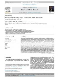
(a) (b) Figure 2.1: 3D gunshot wound path space and a 2D circle section of the Visible Human data set in order to provide complete models of both the female and male anatomies. With these updated models, we could address injuries to the entire body.
2.3 Gunshot wound representation To simplify issues of representation with respect to gunshot wounds, we identify two basic types of gunshot wounds through a body: � Through wounds which consist of an entry and an exit wound and the path taken by a bullet from the entry to the exit wound. � Partially-through/Interior wounds that consist of an entry wound, a bullet lodged in the body and the path from the entry wound to the bullet. Both of these cases are represented with the same three dimensional wound path space model (see Figure 2.1(a)), with the wound path space oriented in such a way that one apex corresponds to the entry wound location and the other to the exit wound or bullet location. The wound path space model is created by taking a chord of a circle and the arc subtended by the chord (Figure 2.1(b)) and rotating the twodimensional gure obtained 360 degrees about the x-axis to form a three-dimensional gure. We x the ratio of the wound path space model's length to its diameter at 100:18, based on values obtained from [4, 15] of the dimensions of permanent and temporary wound cavities produced in injuries involving projectiles. Thus the basis of the gunshot wound wound path space model is a combination of hypotheses about the possible paths taken by a projectile and potential cavitation e�ects that result from the projectile moving through body tissues. In the two cases mentioned above, bullet trajectories are assumed to follow a continuous line/curve. The wound path space representation re ects the maximum expected deviation (from a straight line path) of a continuous line trajectory. To model the region a�ected when dealing with bullet ricochet o� bone, we consider two pairings { one from an entry wound to a particular area of the skeleton and another from this area of the skeleton to either a bullet lodged in the body or an exit wound. The result is two wound path spaces like the one in Figure 2.1(a) joined end 4
to end: one wound path space has an apex at the location of the entry wound and its other apex at the area of the skeleton nicked by the bullet. The second wound path space has one apex at the skeletal nick and its other apex at either a bullet location or an exit wound location.
Figure 2.2: Stab wound path space
2.4 Stab wound representation Two simpli cations are made in modeling the wound path space for a stab wound. The rst is that we assume we are dealing with a xed length blade. The second involves constraining the possible directions of penetration of the blade: given a stab wound to the anterior, posterior or lateral torso, the stab path is placed perpendicular to the skin surface at the point of the stabbing. 1
The wound path space representation for a stab wound is a truncated cone or frustum (Figure 2.2). The smaller base of the frustum is positioned at the blade's entry point, and the wider base is placed internally in such a way that the frustrum is perpendicular to the skin surface. The vee shape of the wound path space re ects uncertainty about the limits of the direction of penetration of the blade to the left and right of the axis perpendicular to the blade's entry point on the skin surface, and the wound path space's circularity represents uncertainty about the orientation of the blade about the axis perpendicular to the entry point on the skin surface.
We refer to the penetrating part of an instrument (knife, screwdriver, ice-pick, etc.) used in a stabbing as a blade. 1
5
Chapter 3 Injury Generation and Assessment 3.1 Introduction and De nitions In the case of gunshot wounds, one or more wound path spaces may compose a penetration path hypothesis. For example, consider a patient presenting with four external wounds to the chest: two anterior (left and right) and two posterior (left and right). If we assume that these correspond to two through wounds (i.e., the patient was shot twice and each bullet entered and exited the body), there are three possible hypotheses (Figure 3.1): 1. The left anterior wound and the left posterior wound are part of the same wound path space, similarly for the right side (i.e., the wound path spaces are parallel from anterior to posterior). 2. The left anterior wound and the right posterior wound are part of the same wound path space, and the right anterior and left posterior wounds belong to the same wound path space (i.e., the wound path spaces cross). 3. The left anterior wound and the right anterior wound belong to the same wound path space, similarly for the left and right posterior wounds (i.e., the wound path spaces are parallel from right to left). These three hypotheses yield markedly di�erent potential consequences for a patient. The third would result in mainly super cial injuries whereas in the rst case there would be the danger of injury to the lungs and abdomen, and in the second there would be danger of injury to the lungs, heart, abdomen and major blood vessels. If we instead assume that the four external wounds described above correspond to partially-through wounds (i.e., the patient was shot four times and there are four bullets lodged within the body), we get a total of twenty-four possible hypotheses. 6
(a)
(b)
(c)
Figure 3.1: Three penetration path hypotheses for two through wounds
3.2 Generating penetration path hypotheses Determining the wound path produced in a stabbing is straightforward given the simplifying assumptions outlined in the preceding chapter; we only need to consider a single wound path space originating from a surface (stab) wound. Multiple gunshot wounds, on the other hand, are complicated by the fact that all possible pairings of external wounds and bullets must be considered. Determining which of the competing sets of pairings is most accurate must be based on further evidence (tests, e.g., roentgenographic results) provided by a physician. Each set of pairings of external gunshot wounds and bullets forms a penetration path hypothesis. Given just one external gunshot wound (i.e., an entry wound), only one possibility exists: there must be a bullet lodged in the body. In this case, a single path can be postulated from the entry wound to the bullet and we have just one penetration path hypothesis. With two external gunshot wounds, we could have a pairing between the two external wounds, which means that one of the wounds must be an entry wound and the other an exit wound, or we could have two pairings from two separate entry wounds to two bullets retained in the body. If we have a total of i external gunshot wounds and j through wounds involving 2j of the i wounds, then the number of ways of choosing a set of pairings of external wounds is
i 2
!
! ! Qj? i ? 2 ::: i ? 2(j ? 1) k 2 2 = j!
1 =0
i ? 2k 2 j!
! = 2j j !(ii?! 2j )!
(3:1)
(for j = 0, Qjk? f (x) = 1). So for instance, given four external wounds as in the rst example ! of section 3.1, and the knowledge that only one through wound exists, we get 4 =1! = 6 possible pairings. That example shows the number of distinct pairings 2 possible (3) for four external wounds given that there are two through wounds. Given i external wounds and j through wounds, where i > 2j , the remaining i ? 2j external wounds are simply entry wounds, and so there must be i ? 2j bullets present in the 1 =0
7
body. Since we very likely do not know which entry wounds match which bullets, we need to consider all (i ? 2j )! possible permutations. This term becomes very large as the number of bullets increases. The number of penetration path hypotheses, given a total of i external gunshot wounds and j through wounds is ! Qj? i ? 2k k 2 i! ( i ? 2 j )! = (3:2) j j! 2 j! 1 =0
In the event that the i external gunshot wounds are all partially-through wounds, the formula above reduces to i! as the example in section 3.1 involving four partiallythrough wounds illustrates (there are 4! or 24 possible hypotheses in this case). The table below gives the number of penetration path hypotheses given i external wounds, j through wounds (j may be 0), and b bullets found internally (where b = i ? 2j ):
i b=0 b=1 b=2 b=3 b=4 b=5 3 3 6 4 3 12 24 5 15 60 120 Table 3.1: Hypotheses given i wounds and b bullets Blank values in the table represent combinations the system rejects as inconsistent, for example, having the total number of external wounds and bullets sum to an odd number. 1
If we don't know how many through wounds or bullets there are, we can sum the number of di�erent penetration path hypotheses possible starting from j = 0 to j = bi=2c, where i is the total number of external gunshot wounds: ! Qj? i ? 2k bX i= c 1 bX i= c k 2 ( i ? 2 j )! = i ! (3:3) j j! j 2 j! j 2
1 =0
2
=0
=0
The results of this sum for di�erent values of i are given in the table below. Each entry corresponds to the sum of the values in a row of table 3.1: With few constraints, there is obviously a large number of possible hypotheses. At present, the system is set up to deal with a maximum of i = 20 external gunshot wounds. The system allows the user to constrain the pairings by specifying which wounds are entry wounds and which are exit wounds (so for example an entry wound is never paired with another entry wound, and an exit wound is never paired with This is predicated on the view that it is highly unlikely for two successive bullets to enter and/or leave the body through the same point(s) on the skin surface. 1
8
i=2 i=3 i=4 i=5 i=6 3 9 39 195 1185 Table 3.2: Hypotheses given i gunshot wounds another exit wound or with a bullet). In the event that it is not known which wounds are entry wounds and which are exit wounds, the wound type is labeled unknown and the wound is paired with other wounds as either an entry or an exit wound. Note that the speci cation of which wounds are entry or exit wounds merely serves to reduce the number of possible hypotheses, since trajectories in both directions are treated as equivalent. 2
Currently, to view any of the individual hypotheses possible for a given number of gunshot wounds and bullets, we pick a hypothesis at random from the set of all possible penetration path hypotheses. A preferable alternative would be to cycle through the set of hypotheses, returning to the rst hypothesis in the set only after the last has been viewed, and future versions of the system will adopt this approach.
3.3 Performing penetration analysis Once we have obtained a set of wound path spaces from a given penetration path hypothesis and from stab wounds, if they exist, we can determine which anatomical parts are a�ected by computing intersections between geometric representations of the di�erent wound path spaces and the anatomical structures in the body. To reduce computation, the structures that intersect a wound path space are found in two steps. First, the smallest axis-aligned parallelepipeds (bounding boxes) that enclose each relevant anatomical structure and each wound path space representation are computed ( gure 3.2 gives the bounding box for the polygonal surface representation of a diaphragm). If a vertex of the bounding box for an anatomical structure lies within the bounding box for a wound path space representation or vice-versa, the gures enclosed by these boxes are noted as candidates for intersection. All anatomical structures that are determined to intersect a wound path space representation in this step are stored for the second step. Since bounding boxes give at best a rough estimate of the shape and size of a gure, the rst step may yield false positives (i.e., detect bounding box intersections in cases where the actual structures enclosed by these boxes are not intersecting). For example, the bounding box for the diaphragm 3
In the rst example involving four external wounds in section 3.1, if the two anterior wounds are marked as entry wounds and the two posterior wounds as exit wounds, hypothesis (c) which postulates that the two anterior wounds belong to the same wound path space and that the two posterior wounds belong to a second wound path space, is eliminated. R 3 Data structures for a gure in Jack automatically include elds for the points comprising the gure's bounding box vertices. 2
9
Figure 3.2: Bounding box for the polygonal surface representation of a diaphragm is much larger than the actual gure due to the concavity of the diaphragm, and as a result, bounding box intersection computations involving the diaphragm may yield false positives. The rst step does not yield false negatives { it will not omit from further consideration any organs that could intersect with a given wound path space. In the second step, for each wound path space we create a list of the anatomical structures produced as possible candidates for intersection in the rst step. We then check the polygons and polygon edges that make up the polygonal surface model of the wound path space for intersection with the polygons and polygon edges that make up the surface model of each anatomical structure on the list. Those anatomical structures determined to intersect with a particular wound path space are stored. This step, called a segment to segment intersection check, is described in more detail below and is potentially more computationally intensive than the rst step since a polygonal surface model of a structure may contain hundreds or thousands of polygons depending on its resolution. The rst step is thus a quick way of reducing the set of objects that need to be considered. The segment to segment intersection check is based on Welton Becket's fast_seg_seg_int() routine for checking whether two polyhedra (which may both be concave) intersect. Given two polyhedra, A and B, it checks whether the polygons that comprise A intersect with the edges of B's polygons and vice-versa. The polygons composing each polyhedron are assumed to be convex: seg_seg_int(A, B) for all edges i in A for all polygons j in B if an edge i intersects with a polygon j return TRUE for all edges i in B for all polygons j in A if an edge i intersects with a polygon j return TRUE return FALSE
10
The algorithm quits, returning the value TRUE as soon as a polygon and edge that intersect are found. In the worst case, the two polyhedra do not intersect and every polygon and edge in polyhedron A is checked against every edge and polygon in polyhedron B before a value of FALSE is returned.
3.4 Calculating injury probabilities After the set of anatomical structures associated with a particular wound path space is determined, it is useful to know how likely it is that each structure in the set was hit. We use penetration probabilities to express the likelihood of involvement of anatomical structures in a given ballistic injury/stabbing. Since the penetration probabilities calculated are at best approximations, our calculations include upper and lower limits of con dence about the accuracy of each probability derived. The interval estimated by these con dence bounds is a range of probabilities that has a 95% chance of including the true penetration probability (it is a 95% con dence interval). The hit probability for a given anatomical structure is calculated by generating a number of experimental trajectories or stab paths (within a wound path space that has already been determined to intersect the structure), and then computing how many of these trajectories or stab paths hit the structure in question. For each wound path space that intersects some anatomical structures, an intersection check is performed between trajectories generated within the wound path space and all anatomical structures that intersect the wound path space. Each trajectory generated either intersects a structure (a hit) or does not (a miss). The total number of trajectories or stab paths that intersect a particular anatomical structure is represented by the binomial random variable X with parameters n and p, where n is the total number of experimental trajectories or stab paths generated and p the probability of a hit. The sample hit probability for the anatomical structure, X , is de ned as the mean number of hits for the particular number of trajectories generated; the total number of hits divided by the total number of randomly generated trajectories: X = Xn (3:4) We use the sample hit probability, X , as an estimate of p because for a binomial random variable, the sample probability of success (the sample hit probability in our case) is the maximum likelihood estimator for the true probability of success (the true hit probability), and as such has many desirable properties. We determine the con dence bounds for a given hit probability using a normal approximation to the binomial distribution. Using the normal distribution to approximate the binomial for cases where X � 0:5 and nX > 5 or X > 0:5 and 11
n(1 ? X ) > 5 is a standard approach in statistics since it cuts down on the length of computation that would be involved in computing probabilities directly from the binomial distribution (see [27, 28, 34]). The con dence bounds for the hit probability are given by: s s 1 0 X (1 ? X ) X (1 ? X ) A @X ? z�= (3:5) n ; X + z�= n 2
2
where n is the sample size (the total number of simulated trajectories) and �=2 is the area under the standard normal density function from ?1 to z�= . The interval described by equation 3.5 corresponds to a 100(1 ? �)% con dence interval. For on-screen display purposes, we write equation 3.5 as s X � z�= X (1 n? X ) 2
2
In order to produce a 95% con dence interval, � is set to 0:05 and the corresponding value for z�= = z : is 1:960 [27, 28]. 2
0 025
The process of generating experimental trajectories for gunshot wounds di�ers slightly from that for stab wounds since the mechanisms of injury for both cases lead to di�erent wound path space models (see gures 2.1(a) and 2.2). A di�erent approach to estimating the hit probabilities for both gunshot and stab wounds would be to make top-down cross-sectional slices of a 3D wound path space model in conjunction with the anatomical structures it intersected. The crosssectional slices of the gunshot wound and stab wound path space models would be a series of concentric circles. For each anatomical structure determined to intersect the wound path space, we could project those cross sectional slices of the wound path space that included slices of the anatomical structure in question onto a 2D plane (see gure 3.3(c)). The probability of injury for the anatomical structure would then be expressed in terms of the portion of its cross-sectional area that intersected the crosssectional area of the wound path space. The injury probability for the anatomical structure would be that of the cross-sectional slice with the maximum area relative to the area of the wound path space cross-section. Estimating the cross sectional area of the anatomical structure could prove di�cult though, given the fact that most anatomical structures do not have cross-sections that correspond to standard geometric shapes.
3.4.1 Generating experimental bullet trajectories
Our method for calculating hit probabilities for ballistic injuries involves simulating possible trajectories. To determine the number of trajectories to use for the probability calculations we experimented with simulating di�erent numbers of trajectories, 12
(a) (b) (c) Figure 3.3: Stab and gunshot wound path space cross-sections starting with 50 trajectories and estimating injury probabilities for the same set of external wounds and anatomical structures. The di�erence in the endpoints of the r con dence interval is 2z�= X n?X , which decreases at a rate inversely proportional p to the square root of the number of simulated trajectories ( n). Currently, we generate 200 trajectories for the purpose of calculating injury probabilities, but the number of trajectories simulated can easily be increased (at the expense of an increase in computation time since more assessments of intersections between trajectories and anatomical structure must be performed). 2
(1
)
The simulated trajectories are either curves that stay within the inner boundaries of the wound path space, or straight lines through the center of the wound path space. Each trajectory extends from one apex of the wound path space to the other and is created from two randomly generated angles. One angle correspends to the amount of a trajectory's deviation from a straight line path and the other to its rotation about a given wound path space apex. The angle corresponding to the amount of the trajectory's deviation from a straight line path is generated using a random number generator from the Free Software Foundation that generates random numbers according to a normal distribution. The random number generator accepts as input the mean angle and variance for the distribution. In this case, the mean is an angle of 0 degrees, corresponding to a straight line path (i.e., the average trajectory is one that does not deviate from a straight line path) and the variance corresponds to (0:5 � MaxAngle) , where MaxAngle is the angle that represents the maximum deviation a trajectory can have from a straight line path while staying within the boundaries of the wound path space model. 2
The value for the variance is selected in keeping with two conventions: � In a normal distribution, 95% of values in the distribution are expected to occur within two standard deviations of the mean for the distribution, and, 13
� In trauma care, injuries that have less than a 5being present (based on clinical
information) are not pursued with costly de nitive diagnostic procedures. Since the standard deviation (0:5 � MaxAngle) is half of the two standard deviations from the center that would encompass 95% of bullet paths, we set the variance to be (0:5 � MaxAngle) . This choice of variance produces trajectories which stay within the boundaries of the wound path space model roughly 95% of the time and trajectories whose paths lie outside these boundaries roughly 5% of the time (see appendix A). 2
The angle representing a trajectory's rotation about a wound path space apex varies from 0 degrees (inclusive) to 360 degrees (not inclusive) and is generated using the C standard library pseudo-random number generator, drand48, which generates uniformly distributed numbers over the interval [0.0, 1.0).
3.4.2 Generating experimental stab paths
To determine stab wound probabilities, we simulate a set of blades within the stab wound path space using two angles to determine how the blade slants and twists in the body. One angle corresponds to the deviation of the blade from a direction perpendicular to the entry point on the skin surface and the second corresponds to the rotation of the blade about an axis perpendicular to the blade's entry point on the skin surface. The angles are generated in much the same way as those for the gunshot trajectories: the rst is produced by the random number generator that obeys a normal distribution, and the second by the C standard library random number generator, drand48. We experimented with the number of blades simulated and increased this number from 50 to 200. Currently 200 blades are generated and tested for intersection with the anatomical structures. As with the gunshot wound trials, the number of blades used in intersection calculations may be increased but the attendant trade-o� between accuracy in estimating probabilities and increases in computation time must be taken into consideration.
3.4.3 Examples: Estimating hit probabilities
We examine here the estimation of hit probabilities for two hypothetical cases; one involving a gunshot wound to the heart and the other a stab wound to the diaphragm.
Example 1
Assume that we discover based on penetration analysis (as outlined in Section 3.3) that a gunshot wound path space penetrates the heart. To obtain the hit probability for the heart given this information, we simulate 200 trajectories and discover that 192 of these simulated trajectories intersect the heart. From equation 3.4, we know that the sample hit probability is given by X = 192 200 = 0:96 14
To obtain the con dence bounds for this sample hit probability according to equation 3.5, we have 1 0 s s 0 : 96(1 ? 0 : 96) 0 : 96(1 ? 0 : 96) A @0:96 ? 1:96 ; 0:96 + 1:96 200 200 = (0:96 ? 0:02716; 0:96 + 0:02716) Thus we know with 95% con dence that in this particular instance, the interval (0:93284; 0:98716) encompasses the actual hit probability for the heart.
Example 2
Assume that we are presented with a stab wound path space and from the penetration analysis performed, the wound path space intersects with the diaphragm. To obtain the hit probability for the diaphragm, we simulate 200 blades at random within the wound path space and discover that 6 of these simulated blades intersect the diaphragm. From equation 3.4, we know that the sample hit probability is given by 6 = 0:03 X = 200 According to equation 3.5, the bounds for this hit probability are given by 1 0 s s 0 : 03(1 ? 0 : 03) 0 : 03(1 ? 0 : 03) A @0:03 ? 1:96 ; 0:96 + 1:96 200 200
= (0:03 ? 0:02364; 0:03 + 0:02364) Thus we know with 95% con dence that in this particular instance, the interval (0:00636; 0:05364) (a range of .6% to 5%) encompasses the actual hit probability for the diaphragm. Note that for 200 sample trajectories/stab paths, if we obtain a sample hit probability over 97.5% or under 2.5% we do not determine the con dence bounds. This is because in these cases n(1 ? X ) and nX are both less than or equal to 5, but n(1 ? X ) and nX should be greater than 5 in order to use a normal approximation to the binomial distribution. (The bounds for sample hit probabilities over 97.5% or under 2.5% can be computed exactly using the binomial distribution, but this involves a very time-consuming series of computations. Alternatively could use Poisson distribution to obtain bounds for these cases).
3.4.4 Determining overall hit probabilities for anatomical structures It is possible that the same anatomical structure could be penetrated by one or more stab wound path spaces as well as multiple gunshot wound path spaces from a given 15
penetration path hypothesis. Currently, when an anatomical structure is penetrated by more than one wound path space, separate hit probabilities are calculated for each wound path space involved with that structure. It would be useful to determine the overall probability that the structure was hit given a penetration path hypothesis as well as any stab wound path spaces that might be present. Imagine that we are presented with a situation in which there are d stab wound path spaces. The probabilities that a structure interesects the stab wound path spaces are independent with unobserved values S ; : : : ; Sd. We are also presented with gunshot wounds. Since we are not certain which entrance wounds match which exit wounds, etc., there are H possible hypotheses. The probabilities of each of the different hypotheses are known and denoted by Q ; : : :; QH . For a given hypothesis, h, there are f gunshot wound path spaces. The probabilties that each of these gunshot wound path spaces intersects an anatomical structure are independent (and independent of the events describing the stab wound) with unobserved values th1 ; : : : ; thf . Hence, for a hypothesis h, the total probability that a given anatomical structure is hit is f Y Yd Ph (structure) = 1 ? (1 ? Si) (1 ? thj ) 1
1
j =1
i=1
This is because the probability that no stab wound path space a�ects the anatomQ d ical structure in question is i (1 ? Si) and the probability that no gunshot wound path space a�ects the anatomical structure is Qfj (1 ? thj ), so theQprobabilityQthat the anatomical structure is not a�ected by any wound path space is di (1 ? Si) fj (1 ? thj ) Qand thus theQprobability that it is a�ected by at least one wound path space is 1 ? di (1 ? Si) fj (1 ? thj ). =1
=1
=1
=1
=1
=1
Finally, the overall probability that the anatomical structure is hit is H X Poverall(structure) = QhPh h=1
The problem is now to obtain an estimate of Poverall (structure) and an associated con dence interval. The same procedure as above allows us to estimate the random variable Si by X i (= fraction of hits for stab wound i) and the random variable thj by Y hj (= fraction of hits for gunshot wound path space j in hypothesis h). Therefore, an estimate for Poverall(structure) is 1 0 d f H Y X Y Qh @1 ? (1 ? X i) (1 ? Y hj )A Poverall (structure) = h=1
Yd
i=1
= 1 ? (1 ? X i) where Th = Qfj (1 ? Y hj ). Note that =1
i=1 PH Q h=1 h
16
H X h=1
= 1.
j =1
QhTh
(3.6)
=) Poverall (structure) =
H X h=1
Qh ?
H X h=1
Qh(1 ? X ) � � � (1 ? X d)(1 ? Y h1 ) � � � (1 ? Y hf ) 1
Let PHh Qh(1 ? X ) � � � (1 ? X d )(1 ? Y h1 ) � � � (1 ? Y hf ) = V . We can rewrite the above equation as Poverall (structure) = 1 ? V , or P = 1 ? V for short. @P = V @X i 1 ? X i H X V = (1 ? X ) � � � (1 ? X d) Qh(1 ? Y h1 ) � � � (1 ? Y hf ) 1
=1
1
h=1
@V = ? V @X i 1 ? Xi @V = ? (1 ? X i) � � � (1 ? X d)QhTh @Y hj 1 ? Y hj Let U = Qdi (1 ? X i) and V = U PHh QhTh The con dence bounds for the overall hit probability are given by v u f H d uX X Y hj (1 ? Y hj ) 1 V X m(1 ? X m) + U X t Q T (1?V )�z�= u h h n n m (1 ? X m ) j (1 ? Y hj ) h =1
=1
2
2
=1
2
2
2
=1
2
=1
2
where n is the sample size, the total number of simulated trajectories/stab paths.
3.5 `Interactive' example In this section we examine a scenario with four external gunshot wounds to the left and ride sides of the chest (like the rst example in 3.1). Figure 3.4 shows top views of the three di�erent penetration path hypotheses for these gunshot wounds and the text output below represents the system's ndings for each hypothesis.
Hypothesis 1 (corresponds to gure 3.4(a)) Computing intersections Skeleton parts in path: Skeleton parts in path: Skeleton parts in path: Skeleton parts in path: Skeleton parts in path:
for bullet/stab path #1 skeleton.lcartilage4 skeleton.lcartilage5 skeleton.sternumbody skeleton.lrib8 skeleton.t8
17
(a)
(b)
(c) Figure 3.4: Overhead views of three penetration path hypotheses
18
Organs Organs Organs Organs Organs Hit Hit Hit Hit Hit Hit Hit Hit Hit Hit
in in in in in
path: path: path: path: path:
heartL.heartL lungsL.lungsL desc_aorta.desc_aorta wind.pipes wind.trachea
probability: probability: probability: probability: probability: probability: probability: probability: probability: probability:
skeleton.lcartilage4: 96.00% +/- 2.72 skeleton.lcartilage5: 0.50% skeleton.sternumbody: 4.50% +/- 2.87 skeleton.lrib8: 95.00% +/- 3.02 skeleton.t8: 19.00% +/- 5.44 heartL.heartL: 93.50% +/- 3.42 lungsL.lungsL: 95.00% +/- 3.02 desc_aorta.desc_aorta: 20.50% +/- 5.60 wind.pipes: 23.00% +/- 5.83 wind.trachea: 25.50% +/- 6.04
Display next path?
yes
Computing intersections for bullet/stab path #2 Skeleton parts in path: skeleton.rrib8 Organs in path: lungsL.lungsL Organs in path: wind.pipes Organs in path: wind.trachea Hit Hit Hit Hit
probability: probability: probability: probability:
skeleton.rrib8: 96.00% +/- 2.72 lungsL.lungsL: 96.00% +/- 2.72 wind.pipes: 2.00% wind.trachea: 2.00%
Hypothesis 2 (corresponds to gure 3.4(b)) Computing intersections for bullet/stab path #1 Skeleton parts in path: skeleton.rrib8 Skeleton parts in path: skeleton.t7 Skeleton parts in path: skeleton.t8 Skeleton parts in path: skeleton.t9 Organs in path: wind.pipes Organs in path: wind.esophagus Organs in path: wind.trachea Organs in path: heartL.heartL Organs in path: lungsL.lungsL
19
Hit Hit Hit Hit Hit Hit Hit Hit Hit
probability: probability: probability: probability: probability: probability: probability: probability: probability:
skeleton.rrib8: 93.50% +/- 3.42 skeleton.t7: 3.00% +/- 2.36 skeleton.t8: 38.00% +/- 6.73 skeleton.t9: 4.00% +/- 2.72 wind.pipes: 21.50% +/- 5.69 wind.esophagus: 13.50% +/- 4.74 wind.trachea: 5.50% +/- 3.16 heartL.heartL: 98.50% lungsL.lungsL: 96.00% +/- 2.72
Display next path?
yes
Computing intersections for bullet/stab path #2 Skeleton parts in path: skeleton.lrib8 Skeleton parts in path: skeleton.t7 Skeleton parts in path: skeleton.t8 Skeleton parts in path: skeleton.t9 Organs in path: desc_aorta.desc_aorta Organs in path: wind.pipes Organs in path: wind.esophagus Organs in path: wind.trachea Organs in path: heartL.heartL Organs in path: lungsL.lungsL Hit Hit Hit Hit Hit Hit Hit Hit Hit Hit
probability: probability: probability: probability: probability: probability: probability: probability: probability: probability:
skeleton.lrib8: 94.00% +/- 3.29 skeleton.t7: 12.50% +/- 4.58 skeleton.t8: 96.00% +/- 2.72 skeleton.t9: 3.00% +/- 2.36 desc_aorta.desc_aorta: 2.50% wind.pipes: 95.50% +/- 2.87 wind.esophagus: 93.00% +/- 3.54 wind.trachea: 9.50% +/- 4.06 heartL.heartL: 97.50% lungsL.lungsL: 92.50% +/- 3.65
Hypothesis 3 (corresponds to gure 3.4(c)) Computing intersections for bullet/stab path #1 No organ/skeleton intersections detected Display next path?
yes
Computing intersections for bullet/stab path #2
20
No organ/skeleton intersections detected
Injury probabilities are also displayed in a pop-up window for easier reading. Figure 3.5 shows the system after evaluating the the rightmost wound path space of the rst hypothesis.
21
Figure 3.5: Penetration path hypothesis with injury probabilities
22
Chapter 4 The User Interface 4.1 Overview
The penetration path assessment system is implemented within the Jack R system using C. It has the menu structure given in table 4.1. In order to use the system, the user must rst load a human body model using the Load Human Figure option. At present, a female torso is loaded (see gure 4.1). Gunshot or stab wounds can be placed on the skin surface at the anterior, posterior, left or right hand side of the body model. Bullets can also be placed within the body. In the case of (multiple) gunshot wounds, the user must generate a penetration path hypothesis to obtain the appropriate set of wound path spaces. The set of anatomical structures injured (along with the injury probability) for a given wound path space is obtained by selecting the Show Intersections option from the menu. The system highlights the structures a�ected and in a separate pop-up window, prints out their injury probabilities. The user can also perform a y-through of the body, tracing the path made by a wound path space to get a sense of the structures it a�ects. To explore the e�ects of projectile ricochet, the user can place nicks on a part of the skeleton that intersects a wound path space and then generate a new hypothesis that takes into account bullet ricochet.
23
Menu Submenu Submenu LoadHumanFigure Wounds AddGunshotWound ToAnterior ToPosterior ToBodyLHS ToBodyRHS AddStabWound ToAnterior ToPosterior ToBodyLHS ToBodyRHS DeleteWound Bullets AddBullet DeleteBullet SkeletalNicks AddSkeletalNick ToAnterior ToPosterior ToBodyLHS ToBodyRHS DeleteNick GenerateHypothesis ShowIntersections RestoreInitialV iew APV iews Table 4.1: Menu structure for penetration path assessment system
24
Figure 4.1: Penetration path assessment system torso model
4.2 System Input Most commands to the penetration path assessment system are entered via a mouse (by clicking on the appropriate menu buttons). To generate a set of wounds and assess their e�ect on anatomical structures the user must click on the di�erent commands in the menu (table 4.1) roughly following the menu order from top to bottom and left to right. Input that the system requires in order to generate hypotheses/assess probabilities includes gunshot wound locations, stab wound locations, bullet positions, and skeletal nick positions. This information is entered into the system via the mouse. 25
4.2.1 Wound placement
Surface gunshot and stab wounds are placed on the body relative to the skeleton { the skin surface is made transparent and other structures are temporarily hidden so that the skeleton shows through as a landmark. The user places a wound on any part of the skin surface by clicking on that surface. Since the body model is threedimensional, for any anterior skin surface point clicked on by the user, there is a corresponding posterior skin surface point, and the same holds for the left and right sides of the body. The system accepts the surface closest to the user as the intended placement point of the surface wound. For gunshot wounds, the system displays a
attish cylindrical wound model at the point of contact. For stab wounds, the wound path space for a stab wound is generated from the point of contact, and projects into the body.
4.2.2 Bullet and skeletal nick placement
As with surface wounds, bullets are placed relative to the skeleton. The user rst xes the x ? y position of the bullet (i.e., the position of the bullet relative to the top, bottom, and left and right sides of the body) using crosshairs that lie within the x ? y plane and then the y ? z position (the depth of the bullet relative to the front and rear of the body). Skeletal nicks are placed by clicking on a point of the skeleton's surface. The nick is placed at the surface point closest to the user.
4.3 System Output Output from the system comes in two forms: text { names of structures suspected to be injured and the probability they are involved in injury; graphics { color coding of the graphical display to highlight the three-dimensional models of anatomical structures a�ected by a particular wound path space. Visual reinforcement of the text output is also provided by through-body navigations, whereby a user can essentially \follow" a bullet or stab path through the 3D models of the organs and observe which organs lie in the path of the wound path space.
26
Chapter 5 Applications The penetration path assessment system is designed to work with the TraumAID [31, 35], and MediSim [3] systems developed at the University of Pennsylvania, both of which suggest actions that should be taken by medical personnel when faced with patients su�ering from penetrating injuries. The system is also a potentially useful tool for aiding medical students in learning about anatomy and perhaps in refreshing experts' memories about the spatial relations of di�erent anatomical structures.
5.1 TraumAID TraumAID is an expert system designed to assist physicians with the diagnosis and treatment of multiple trauma. The TraumAID system integrates diagnostic reasoning, planning, and action. Currently, TraumAID uses a rule-based reasoner to identify diagnostic and therapeutic goals appropriate to a particular patient's state. The planner then advises the physician on bene cial actions that should be performed. Recently there has been a push to move away from rule-based reasoning within TraumAID and to instead use belief networks to de ne diagnostic or therapeutic goals. Prior probabilities must be assigned to di�erent nodes in the belief net in order to drive the network. Injury probabilities calculated from E-codes and ICD-9 codes collected from an existing Pennsylvania Trauma Registry database of 137,500 patients [26, 13], could be linked with the penetration probabilities generated by the penetration path assessment system to provide the prior probability values needed with regard to anatomical involvement of wounds. In addition, there is a need to extend TraumAID's reasoning about anatomy: at present the body is represented as being partitioned into di�erent regions, and a whole/part hierarchy is used to represent areas of the body to which injuries have occurred. So for example, a report of a penetrating injury to the left chest in TraumAID could potentially involve the lungs, heart, diaphragm or even the upper part of the abdomen close to the diaphragm. Di�erent people might come up with di�erent 27
hypotheses about injury due to the same wound(s) given this sort of general information (though feedback about patient signs and symptoms would help to eliminate some of the conjectures). By reducing uncertainty about the location of penetrating wounds, the penetration path system constrains the set of anatomical structures that could be associated with the wounds and possibly the set of injuries that would be suspected given these wounds. Since information about speci c anatomical structures can be obtained from the penetration path assessment system, there is a framework for deeper anatomical reasoning which a system that reasoned only about larger regions of the body might not be able to provide.
5.2 MediSim Medisim is a system that represents simulated medics interacting with simulated casualties within local or network virtual environments. It is designed to be used for the training and evaluation of medical corpsmen and civilian EMTs. Using injury models appropriate to either a battle eld or civilian situation, a set of physical and behavioral manifestations in a simulated casualty are determined and portrayed on a 3D body model. Wound and injury types for simulated casualties can be coupled probabilistically to a simulated battle eld. Probabilities of anatomical involvement generated by the penetration path system can be used to update the posterior probabilities of particular injuries simulated within MediSim.
5.3 Educational As stated above, the penetration path assessment system could aid medical students in learning about anatomical structures by providing a 3D environment in which various anatomical structures can be observed at di�erent angles and distances in relation to other structures or without obstruction since gures in the Jack R environment can be made to \disappear" by turning them o� temporarily. Even experts might bene t from the system by having it con rm/disprove their notions about the spatial relationships among the di�erent anatomical structures. This issue apparently does arise occasionally in medical practice as the case description below [14] illustrates: A patient presented to the Emergency Center with a knife embedded in the right lower paraspinal chest and no other abnormal physical ndings on examination. Anterior-posterior and lateral roentgenograms of the chest showed the tip of the knife just anterior to the seventh thoracic vertebra with the blade just to the right of the vertebra. The physicians caring for patient recognized that the descending aorta was anatomically too far to the left of the vertebral column to be injured, but were concerned enough about anatomical proximity to the esophagus to consider a contrast study 28
of the esophagus. The availability of an atlas of cross sectional anatomy of the thorax at the T-7 level showed that the esophagus was also too far to the left at this level to be injured and the contrast study was not done based on this information. The knife was removed in the operating room and the patient was observed. He was treated for a delayed pneumothorax and recovered without further consequences.
29
Chapter 6 Future Work 6.1 Improvements to anatomical and wound path space models
6.1.1 Body Type
To make the assessments produced by the penetration path system more re ective of actual patient information, we need to incorporate into the system full-body models for both males and females that can easily accommodate di�erences in shapes, sizes and relative organ placements of di�erent individuals. This is because the internal impact of a set of surface wounds on two people of di�erent sizes or shapes will tend to di�er. One way of addressing this would be to scale the polygonal surface models of anatomical parts to t di�erent individuals' pro les prior to injury generation and assessment. We plan to take advantage of the Visible Human data set in order to provide complete models of both the female and male anatomies. With these updated models, we could address injuries to the complete body.
6.1.2 Anatomical Structure Representation
The polygonal surface models currently in use o�er the following advantages:
� The amount of data needed for representation of anatomical structures is not
overwhelming but still represents the structures adequately (for example, the low resolution heart model used in the system is made up of 752 polygons while the equivalent high resolution model has 3466 polygons and takes twice as much time to display)
� Assessments of injury to organs and associated probabilities can be computed relatively quickly (it takes an average of 58 seconds for an experienced user to 30
interactively load the human torso, enter two external wounds, generate a hypothesis and compute the penetration probabilities on a Silicon Graphics Indigo 2), and � The polygonal surface representation is compatible with existing software in use at the University of Pennsylvania's Center for Human Modeling and Simulation. However, with the surface models, we cannot o�er the user any details of the anatomy beyond the surface of a particular structure. To obtain such a detailed level of information about the anatomy, it would be necessary to use volumetric models for the anatomical structures rather than surface models. A drawback to using volumetric models is that representing anatomical structures would require a tremendous amount of data[23]. A compromise could be to perform the organ intersection and injury probability assessments using polygonal surface models, and to utilize volumetric models mainly for through-body navigations.
6.1.3 Stab path treatment
At present, the angle of entry, and blade width and length of the instrument used in a stabbing are assumed to be xed. It would be desirable to allow for variations in these factors by eliciting information about blade length, width and entry angle from the user.
6.2 Constraining the penetration path hypotheses By allowing feedback as to the status of a patient in terms of test results and physicians' ndings, we could eliminate certain penetration path hypotheses if the results obtained do not support such hypotheses. This entails developing a system which given a set of penetration path hypotheses and their associated probabilities as well as patient signs and symptoms (or physician's ndings) would determine based on the signs and symptoms (or ndings) which hypotheses were likely and rule out those deemed unlikely. This would also involve re ning (increasing) the penetration probabilities for anatomical structures associated with hypotheses that are not ruled out and decreasing the penetration probabilities of those structures associated with ruledout hypotheses.
6.3 User Interface It would be useful to obtain feedback on the ease of use of the system from medical personnel and information on features that might be desired by physicians in di�erent specialties. Information gathered would also be useful in determining the most e�ective ways of presenting the system's output to the user. 31
Chapter 7 Conclusion We have presented a graphical user interface for assessing the impact of gunshot and stab wounds on a human model in terms of the anatomical structures a�ected and the probability of injury to these structures. Since anatomical knowledge is critical for emergency medical personnel to evaluate possible organ involvement in penetrating injury, a goal of the system is to aid in visualizing a�ected structures. Applications of the system include assisting diagnostic programs like TraumAID in improving their anatomical reasoning, aiding training systems such as MediSim in deriving posterior probabilities of particular types of injuries, and helping medical students in learning about anatomy. The system has potential emergency room applicability: attending physicians could obtain the system's penetration path analysis at the same time that roentgenographic information is made available to them.
32
Appendix A Changing the Variance Hit probabilities for the same set of gunshot wounds given di�erent variances
Jack window X-Y coordinates for gunshot wounds
Anterior gunshot wound x coordinate: 357 Anterior gunshot wound y coordinate: 408 Posterior gunshot wound x coordinate: 269 Posterior gunshot wound y coordinate: 417 Number of trajectories generated : 200
We use a random number generator (Normal rnd(mean, variance, generator)) which generates numbers based on a normal distribution. For the output below it is called with a mean angle of 0 and a variance of (Fraction � Max angle) , where Max angle (20.402820 degrees) is the angle that produces a trajectory with the maximum deviation from a straight line path that still stays within the boundaries of the wound path space model. At present, a trajectory whose deviation exceeds this maximum is automatically considered a miss. 2
-------------------------------------------------------------------0) Variance : (0.75*Max_angle)^2 Hit Hit Hit Hit Hit Hit
probability: probability: probability: probability: probability: probability:
skeleton.lrib8: 81.00% +/- 5.44 heartL.heartL: 51.00% +/- 6.93 lungsL.lungsL: 80.00% +/- 5.54 desc_aorta.desc_aorta: 1.00% wind.pipes: 4.00% +/- 2.72 wind.trachea: 0.50%
33
skeleton.lrib8: Number of trajectories with deviations over the max: 34 heartL.heartL: Number of trajectories with deviations over the max: 34 lungsL.lungsL: Number of trajectories with deviations over the max: 40 desc_aorta.desc_aorta: Number of trajectories with deviations over the max: 42 wind.pipes: Number of trajectories with deviations over the max: 37 wind.trachea: Number of trajectories with deviations over the max: 44 -------------------------------------------------------------------1) Variance : (0.625*Max_angle)^2 Hit Hit Hit Hit Hit Hit
probability: probability: probability: probability: probability: probability:
skeleton.lrib8: 87.50% +/- 4.58 heartL.heartL: 56.00% +/- 6.88 lungsL.lungsL: 90.00% +/- 4.16 desc_aorta.desc_aorta: 2.50% wind.pipes: 2.00% wind.trachea: 2.00%
skeleton.lrib8: Number of trajectories with deviations over the max: 20 heartL.heartL: Number of trajectories with deviations over the max: 25 lungsL.lungsL: Number of trajectories with deviations over the max: 20 desc_aorta.desc_aorta: Number of trajectories with deviations over the max: 15 wind.pipes: Number of trajectories with deviations over the max: 18 wind.trachea: Number of trajectories with deviations over the max: 18 -------------------------------------------------------------------2) Variance : (0.5*Max_angle)^2 Hit Hit Hit Hit Hit Hit
probability: probability: probability: probability: probability: probability:
skeleton.lrib8: 91.00% +/- 3.97 heartL.heartL: 60.00% +/- 6.79 lungsL.lungsL: 95.50% +/- 2.87 desc_aorta.desc_aorta: 2.00% wind.pipes: 0.50% wind.trachea: 2.00%
skeleton.lrib8: Number of trajectories with deviations over the max: 14 heartL.heartL: Number of trajectories with deviations over the max: 15 lungsL.lungsL: Number of trajectories with deviations over the max: 9 desc_aorta.desc_aorta: Number of trajectories with deviations over the max: 8 wind.pipes: Number of trajectories with deviations over the max: 14 wind.trachea: Number of trajectories with deviations over the max: 8
34
-------------------------------------------------------------------3) Variance : (0.375*Max_angle)^2 Hit Hit Hit Hit Hit Hit
probability: probability: probability: probability: probability: probability:
skeleton.lrib8: 97.50% heartL.heartL: 49.50% +/- 6.93 lungsL.lungsL: 99.50% desc_aorta.desc_aorta: 2.00% wind.pipes: 1.00% wind.trachea: 0.50%
skeleton.lrib8: Number of trajectories with deviations over the max: 1 heartL.heartL: Number of trajectories with deviations over the max: 1 lungsL.lungsL: Number of trajectories with deviations over the max: 1 desc_aorta.desc_aorta: Number of trajectories with deviations over the max: 1 wind.pipes: Number of trajectories with deviations over the max: 1 wind.trachea: Number of trajectories with deviations over the max: 1 -------------------------------------------------------------------4) Variance : (0.25*Max_angle)^2 Hit Hit Hit Hit Hit Hit
probability: probability: probability: probability: probability: probability:
skeleton.lrib8: 98.00% heartL.heartL: 47.50% +/- 6.92 lungsL.lungsL: 100.00% desc_aorta.desc_aorta: 0.00% wind.pipes: 1.00% wind.trachea: 0.00%
skeleton.lrib8: Number of trajectories with deviations over the max: 0 heartL.heartL: Number of trajectories with deviations over the max: 0 lungsL.lungsL: Number of trajectories with deviations over the max: 0 desc_aorta.desc_aorta: Number of trajectories with deviations over the max: 0 wind.pipes: Number of trajectories with deviations over the max: 0 wind.trachea: Number of trajectories with deviations over the max: 0 -------------------------------------------------------------------5) Variance : (0.125*Max_angle)^2 Hit probability: skeleton.lrib8: 100.00% Hit probability: heartL.heartL: 42.50% +/- 6.85 Hit probability: lungsL.lungsL: 100.00%
35
Hit probability: desc_aorta.desc_aorta: 0.00% Hit probability: wind.pipes: 0.00% Hit probability: wind.trachea: 0.00% skeleton.lrib8: Number of trajectories with deviations over the max: 0 heartL.heartL: Number of trajectories with deviations over the max: 0 lungsL.lungsL: Number of trajectories with deviations over the max: 0 desc_aorta.desc_aorta: Number of trajectories with deviations over the max: 0 wind.pipes: Number of trajectories with deviations over the max: 0 wind.trachea: Number of trajectories with deviations over the max: 0 -------------------------------------------------------------------6) Variance : (0.0625*Max_angle)^2 Hit Hit Hit Hit Hit Hit
probability: probability: probability: probability: probability: probability:
skeleton.lrib8: 100.00% heartL.heartL: 28.00% +/- 6.22 lungsL.lungsL: 100.00% desc_aorta.desc_aorta: 0.00% wind.pipes: 0.00% wind.trachea: 0.00%
skeleton.lrib8: Number of trajectories with deviations over the max: 0 heartL.heartL: Number of trajectories with deviations over the max: 0 lungsL.lungsL: Number of trajectories with deviations over the max: 0 desc_aorta.desc_aorta: Number of trajectories with deviations over the max: 0 wind.pipes: Number of trajectories with deviations over the max: 0 wind.trachea: Number of trajectories with deviations over the max: 0 -------------------------------------------------------------------7) Variance : (0.0*Max_angle)^2 = 0.0 Hit Hit Hit Hit Hit Hit
probability: probability: probability: probability: probability: probability:
skeleton.lrib8: 100.00% heartL.heartL: 0.00% lungsL.lungsL: 100.00% desc_aorta.desc_aorta: 0.00% wind.pipes: 0.00% wind.trachea: 0.00%
skeleton.lrib8: Number of trajectories with deviations over the max: 0 heartL.heartL: Number of trajectories with deviations over the max: 0 lungsL.lungsL: Number of trajectories with deviations over the max: 0
36
desc_aorta.desc_aorta: Number of trajectories with deviations over the max: 0 wind.pipes: Number of trajectories with deviations over the max: 0 wind.trachea: Number of trajectories with deviations over the max: 0 --------------------------------------------------------------------
37
Bibliography [1] Anson, B. J. Atlas of Human Anatomy. W. B. Saunders, Philadelphia, 1950. [2] Badler, N., C. Phillips, and B. Webber. Simulating Humans: Computer Graphics, Animation, and Control. Oxford University Press, Oxford, 1993. [3] Badler, N., B. Webber, J. R. Clarke, D. Chi, M. Hollick, N. Foster, E. Kokkevis, D. Metaxas, O. Ogunyemi, J. Kaye, R. Bindiganavale. MediSim: Simulated Medical Corpsmen and Casualties for Medical Forces Planning and Training, The National Forum: Military Telemedicine On-Line Today. Research, Practice and Opportunitie s, IEEE Computer Society Press, 1995. [4] Celens, E., M. Pirlot and A. Chabotier. Terminal E�ects of Bullets Based on Firing Results in Gelatin Medium and on Numerical Modeling, The Journal of Trauma: Injury, Infection, and Critical Care, 1996. 40(3): pp. S27 - S30. [5] Charniak, E.. Bayesian networks without tears. AI Magazine, Vol. 12, No. 4: 50 - 63, 1991. [6] Clarke, J. R.. A tutorial series on surgical decision making. Theoretical Surgery 5:105 - 106, 1990. [7] Clarke, J. R., and C. Z. Hayward. A scienti c approach to surgical reasoning. I. Diagnostic accuracy - sensitivity, speci city, prevalence, and predictive value. Theoretical Surgery 5:129 - 132, 1990. [8] Clarke, J. R.. A scienti c approach to surgical reasoning. II. Probability revision - odds ratios, likelihood ratios, and Bayes' theorem. Theoretical Surgery 5:206 210, 1990. [9] Clarke, J. R., and T.F. O'Donnell Jr. A scienti c approach to surgical reasoning. III. What is abnormal? Test results with continuous values and receiver operating characteristic (ROC) curves. Theoretical Surgery 6:45 - 61, 1991. [10] Clarke, J. R., and D. L. Roseman. A scienti c approach to surgical reasoning. IV. Resolving tradeo�s - decision trees and decision analysis. Theoretical Surgery 6:110 - 115, 1991. 38
[11] Clarke, J. R.. A scienti c approach to surgical reasoning. V. Patients' attitudes. Theoretical Surgery 6:166 - 176, 1991. [12] Clarke, J. R., and T.F. O'Donnell Jr. A scienti c approach to surgical reasoning. VI. Thresholds and con dence. Theoretical Surgery 6:177 - 183, 1991. [13] Clarke, J. R., M. Kritikos, B. L. Webber, L. W. Bain, and W. S. Copes. Predictions of Injuries from Mechanism in 137,500 Seriously Injured Trauma Center Patients. 1995 Annual Meeting of the American Assoc. for Surgery in Trauma. Halifax, NS, Canada, September 1995. [14] Clarke, J. R., personal communication (via-email), April 1995. [15] V. DiMaio. Gunshot Wounds - Practical Aspects of Firearms, Ballistics, and Forensic Techniques. Elsevier, New York, 1985. [16] Eisler, R. D., A. K. Chatterjee, G. H. Burghart, and J. A. O'Keefe IV. Casualty Assessment of Penetrating Wounds from Ballistic Trauma. Tech Report MRCCOM-R-93-0402(R1), Mission Research Corporation: 1993. [17] Eisler, R. D., A. K. Chatterjee, and G. H. Burghart. Simulation and Modeling of Penetrating Wounds from Small Arms Health Care in the Information Age, IOS Press and Ohmsha, 1996. [18] Fackler, M.L., R.F. Bellamy, and J. A. Malinowski. The Wound Pro le: Illustration of Missile-Tissue Interaction. Journal of Trauma, 1988. 28 (Supplement 1): pp. S21-29. [19] Foley, J., A. van Dam, S. Feiner, and J. Hughes. Computer Graphics: Principles and Practice Addison-Wesley, Reading, Massachusetts, 1992. [20] Granieri, J., M. Hollick, and C. Phillips. The Jack User's Guide, version 5.8. Center for Human Modeling and Simulation, the University of Pennsylvania, 1994. [21] Grant, J. C. Grant's Atlas of anatomy / edited by James E. Anderson, 8th ed. Williams and Wilkins, Baltimore, 1983. [22] Gray, H.. Gray's anatomy / edited by Peter L. Williams, 37th ed. C. Livingstone, Edinburgh, 1989. [23] Karpf, L. J.. Model-based penetration path calculations for the diagnosis of multiple trauma. Master's Thesis, University of Pennsylvania, 1990. [24] Kaye, J. M.. TrauMAP: Integrating Anatomical and Physiological Simulation. Ph. D. Dissertation Proposal, University of Pennsylvania, 1995. 39
[25] Korver, M. and P. J. F. Lucas. Converting a rule-based expert system into a belief network. Medical Informatics. Vol. 18 No. 3: pp. 219-241. 1993. [26] Kritikos, M.. TraumAID: Building a belief network from the current rule-based expert system. Senior Thesis, University of Pennsylvania, 1995. [27] Larsen, R. J. and M. L. Marx. An Introduction to Mathematical Statistics and its Applications Prentice-Hall, Englewood-Cli�s, New Jersey, 1986. [28] Milton, J. S., and J. C. Arnold. Introduction to probability and statistics: principles and applications for engineering and the computing sciences McGraw-Hill, New York, 1990. [29] Ogunyemi, O., J. Kaye, B. Webber, and J. R. Clarke. Generating Penetration Path Hypotheses for Decision Support in Multiple Trauma Symposium on Computer Applications in Medical Care, 1995. 19: pp. 42 - 46. [30] Phillips, C., and J. Granieri. Programming with Jack, version 5.8. Center for Human Modeling and Simulation, the University of Pennsylvania, 1993. [31] Rymon, R., B. L. Webber, and J. R. Clarke. Progressive Horizon Planning - Planning Exploratory-Corrective Behavior. IEEE Transactions on Systems, Man, and Cybernetics 23(6), November 1993. [32] Satava, R. M.. Virtual Reality surgical simulation: the rst steps. Surgical Endoscopy, 1993. 7: pp. 203 - 205. [33] Swan, K. and R. Swan. Gunshot Wounds: Pathophysiology and Management Year Book Medical Publishers, Chicago, 1989. [34] Tallarida, R. J. Pocket Book of Integrals and Mathematical Formulas, 2nd ed. CRC Press, Boca Raton, Florida, 1992. [35] Webber, B., R. Rymon, and J. R. Clarke. Flexible Support for Trauma Management through Goal-Directed Reasoning and Planning. Arti cial Intelligence in Medicine 4(2), April 1992, pp. 145-163. [36] West, J. G., D. D. Trunkey, and R. C. Lim. Systems of trauma care: A study of two counties. Archives of Surgery, 1979, 114:455-460. [37] Wind, G., R.W. Finley, and N. M. Rich. Three-dimensional Computer Graphic Modeling of Ballistic Injuries. Journal of Trauma, 1988. 28 (Supplement 1): pp. S16-20.
40