Dec 10, 2007 - is suitable for assurance-driven development, i.e., for de- velopments in which ... Software Engineering (POSE) [HRJ08], can be used in this role, and describe in ...... High Assurance System Engineering (HASE), Dallas,. Texas, 2007. ... Addison-Wesley Publishing Company, 1st edition,. 2001. [MHR07a] ...
ISSN 1744-1986
Technical Report No 2007/15
Assurance-driven development in Problem Oriented Engineering
Jon G. Hall Lucia Rapanotti
10th December 2007
Department of Computing Faculty of Mathematics and Computing The Open University Walton Hall, Milton Keynes MK7 6AA United Kingdom http://computing.open.ac.uk
Assurance-driven development in Problem Oriented Engineering Jon G. Hall Lucia Rapanotti Centre for Research in Computing The Open University, UK {J.G.Hall,L.Rapanotti}@open.ac.uk
Abstract
In previous work [HMR07, MHR07b, MHR07a, MHR07c], we have shown how the Problem Oriented Engineering (POE) framework, instantiated as Problem Oriented Software Engineering (POSE) [HRJ08], can be used in this role, and describe in [HMR07] how a ‘POSE safety process pattern’ can be defined through which assurance-driven design can proceed. In this paper, we generalise many of the characteristics of that process pattern from its POSE inception to engineering design under POE. As well as allowing assurance-driven design, the generalised POE process pattern has the following additional characteristics:
Problem Oriented Engineering (POE) is a Gentzen-style ‘natural’ framework for engineering design. As such, POE supports rather than guides its user as to the particular sequence of design steps that will be used; the sequencing is user determined as that most appropriate to the context of application. In this paper, however, we suggest a sequencing of steps and interactions with stake-holders that is suitable for assurance-driven development, i.e., for developments in which the argument of fitness-for-purpose is produced during design.
• it supports each of the engineering design process elements described above;
1
Introduction
• it provides a vehicle for the assurance case driven design, with documentation and analysis of the rationale for decisions;
By engineering design (shortly, design), we refer to the creative, iterative and often open-ended process of conceiving and developing products, systems and processes (adapted from [EDD]). Engineering design processes by necessity include the identification and clarification of requirements, the understanding and structuring of the context into which the engineered system will be deployed, the specification of a design for a solution that can ensure satisfaction of the requirements in context, and the construction of arguments, convincing for all validating stake-holders, that the engineered system will provide the functionality and qualities that are needed. The involvement of stake-holders motivates the development of an explicit assurance case to collects evidence of the designed artefact’s fitness for purpose. Traditionally, assurance cases have been compiled after the fact: the artefact being designed and then evidence of its fitness-for-purpose collected. The distancing of the artefact and the argument requires higher levels of design expertise and can be more costly as errors are found only late in the process, and has led to calls for evidence is gathered during development, even acting as a driver for the design, what we have termed assurance driven design.
• it allows for the explicit consideration of the risks involved in design; • it allows rich traceability between requirements, domain assumptions and system components; • it is parametrisable for use in diverse engineering domains. The paper is structured as follow. Section 2 provides a brief introduction to POE. Section 3 introduces the POE process pattern. Section 4 presents the case study. Section 5 reflects on what has been achieved in the paper.
2
Problem Oriented Engineering
A full presentation of the POE framework is beyond the scope of this paper but can be found, instantiated for software design, in [HRJ08]. POE is a formal system for working with non-formal and formal descriptions. Problem Oriented Engineering (POE) is a Gentzen-style natural framework for engineering design (see, for instance, 1
[Pel99]). As such, POE supports rather than guides its user as to the particular sequence of design steps that will be used; the user choosing the sequence of steps that they deem most appropriate to the context of application. The basis of POE is the problem sequent for representing design problems requiring designed solutions. The transformations defined in POE transform problems as sequents into others in ways that preserve solutions (in a sense that will become clear). When we have managed to transform a problem to axioms1 we have solved the problem, and we will have a designed solution for our efforts. POE is designed to work with problems not propositions as in the original natural deduction: the characteristic that distinguishes it most from natural deduction is the guarding of transformations by justification obligations, the discharge of which establishes the ‘soundness’ of the application with respect to stake-holders. Natural deduction is based on a single absolute notion of correctness provided by proof whereas, through justifications, POE caters for the engineering notion of fitness-for-purpose, something that is often very far from correctness. In the following we recall some of the basic definitions for the framework tat will be used during the case study. The interested reader is referred to http://mcs.open.ac.uk/jgh23/ for more detail.
2.1
as expressing a wish. As to the requirement’s phenomena: cons are those constrained by R, i.e., whose occurrence is constrained by the requirement, and whose occurrence the solution affects in providing a solution; refs are those referenced by R, i.e., whose occurrence is referred to but not constrained by the requirement. A solution is also a domain, S(p)co = N : E, intended to solve a problem, i.e., when introduced into the problem context will satisfy the problem’s requirement. The possible descriptions of a solution range over many forms, from high-level specification through to detailed designs. As a domain, a solution has controlled, observed and unshared phenomena; the union of the controlled and observed sets is termed the specification phenomena for the problem. A problem’s elements come together in POE in a problem sequent2 : D1 (p1 )co11 , . . . , Dn (pn )conn , S(p)co ` Rcons ref Here ` is the problem builder and reminds us that it is the relation of the solution to its context and to the requirements that we seek to explore. By convention, the problem’s solution domain, S, is always positioned immediately to the left of the `. The descriptions of a problem’s elements may be in any language, different elements being described in different languages, should that be appropriate. So that descriptions in many languages may be used together in the same problem, POE provides a semantic meta-level for the combination of descriptions; notationally, this is a role of the ‘,’ that collects into a problem sequent the domains that appear around the turnstile, formally making each visible to the others3 .
Problems
A problem, as defined in POE, has three elements: a realworld context, W, a requirement, R, and a solution, S. The problem context is a collection of domains (W = D1 , ..., Dn ) described in terms of their known, or indicative, properties, which interact through their sharing of phenomena (i.e, events, commands, states, etc. [Jac01b]). More precisely, a domain is a set of related phenomena that are usefully treated as a behavioural unit for some purpose. A domain D(p)co = N : E has name (N) and description (E), the description indicating the possible values and/or states that the domain’s phenomena (in p ∪ c ∪ o) can occupy, how those values and states change over time, how phenomena occur, and when. Of the phenomena: c are those controlled by D, i.e., visible to, and sharable by, other domains but whose occurrence is controlled by D; o are those observed by D, i.e., made visible by other domains, whose occurrence is observed by D; p are those unshared by D, i.e., sharable by no other domain. A problem’s requirement states how a proposed solution description will be assessed as the solution to that problem. Like a domain, a requirement is a named description with phenomena, Rcons refs = N : E. A requirement description should always be interpreted in the optative mood, i.e.,
2.2
Problem transformation
Problem transformations capture discrete steps in the problem solving process. Many classes of transformations are recognised in POE, reflecting a variety of engineering practices reported in the literature or observed elsewhere. Problem transformations relate a problem and a justification to (a set of) problems. Problem transformations conform to the following general pattern. Suppose we have problems W, S ` R, Wi , Si ` Ri , i = 1, ..., n, (n ≥ 0) and justification J, then we will write: W1 , S1 ` R1
... W, S ` R
Wn , Sn ` Rn
[NAME] hhJii
2 As here, for brevity, we will sometimes omit the phenomena decorations and descriptions in W, S and R whenever they can be inferred by context. 3 A situation similar to that found in the propositional calculus in which conjunction and disjunction, etc, serve to combine the truth values of the atomic propositions.
1 An axiomatic problem is a problem whose known fit-for-purpose solution is known.
2
to mean that, derived from an application of the NAME problem transformation schema (discussed below):
J USTIFICATION J: reference.
D ESCRIPTIONS & P HENOMENA: The collection of descriptions and phenomena of the domains and requirements introduced into the problem by the step or the manipulations defined thereon by the step. For an application of the Context Interpretation step, for instance, a detailed description of the elements of W and W 0 would be given, alongside any relationship that holds between them, such as shared descriptions, etc.
S is a solution of W, S ` R with adequacy argument (CA1 ∧ ... ∧ CAn ) ∧ J whenever S1 , ..., Sn are solutions of W1 , S1 ` R1 , ..., Wn , Sn ` Rn , with adequacy arguments CA1 , ..., CAn , respectively. Engineering design under POE proceeds in a step-wise manner: the initial problem forms the root of a development tree with transformations applied to extend the tree upwards towards its leaves. Branches are completed by problem transformations that leave the empty set of premise problems4 .
2.3
C ONCERN: Name S TATUS: Status A concern (c.f., [Jac01b]) is something that is important to the development, presumably because it relates to some stake-holder in the process. In high integrity development, for instance, the reliability concern is likely to arise; a design that does not address such a concern in such a context is likely to be unvalidatable. The status of a concern is one of pending, discharged, undischargeable. The work appertaining to the discharge of a concern is structured: each concern has associated with it the following:
Assurance-driven Development
A problem transformation schema defines a named class of problem transformations, describing the way in which the conclusion problem (that below the line) is related to the premise problem(s) (those above the line). How a problem is transformed is given in a problem transformation schema by pattern matching of the elements of the conclusion problem, with those matched elements repeated as appropriate to specialise both the premise problem(s) and justification obligation (explained below). Here is the transformation schema for CONTEXT INTER PRETATION by which the context W is interpreted as W 0 : W 0, S ` R W, S ` R
C LAIM: The statement of the claim(s) that will discharge the concern; A RGUMENT & E VIDENCE: The reason to believe each claim (or the reason it does not hold); R ISKS: A description of the risks involved in continuing the development should the concern fail to be discharged, and/or the secondary risk introduced by the discharge of the concern. A description of the treatment of risks residual to the step.
[C ONTEXT I NTERPRETATION] hhExplain and justify the use of W 0 over Wii
A concern established as part of a step may be addressed (and therefore discharged) in design steps subsequent to that in which it is established, i.e., when, as part of other design steps, evidence in support of its associated claim is discovered. The argument and evidence may, therefore, make reference to other concerns, arguments and evidence in the design tree. The validity concern for a step, that subject to external validation by problem- and solution-owning stake-holders, will typically be required to ensure that relationships between concerns and their discharge are adequate.
The justification obligation is a condition that must be discharged for an application of a schema to be solution preserving. Each schema has its own general form of justification obligation; that for CONTEXT INTERPRETATION is shown in the rule. However, the specific form will depend upon the development context as well as other factors. A discharged justification obligation contributes towards the adequacy argument: in assurance-driven design, the needs of an assurance case will be paramount in determining the justifications that should be sought, and so which rules and in which sequence they should be applied. The structure of a justification within assurance-driven development has a special form, reflecting the needs of the assurance case that will be designed alongside the product. Suppose, for instance, we wish to perform the step labelled S TEP I D which transforms the problem P under the NAME transformation schema, then the justification will typically consist of the following: S TEP I D:
A justification can be named for ease of
C ONCERN: Step Validity S TATUS: Status The status of the step validity concern, possible values include pending, signed-off, undischargeable A RGUMENT & E VIDENCE: Explanation of the status after validation, including the relationships where evidence was gathered in the design, and the treatment chosen for the residual risk of the step. S IGNATORY: To recognise the stake-holder or stakeholders that signed-off the step.
Application of NAME to problem P Each element is optional, typically depending on the developmental stage and context.
4 The premise set will be empty if the problem is axiomatic, as defined in section Section 2.
3
3
POE instantiated for safety-critical software development
to form the basis of a solution. The nature of the choice is then something like “Is there good reason to believe that a solution can exist based on this architecture?” As such, it is clear that the decision made need to be revisited later during development.
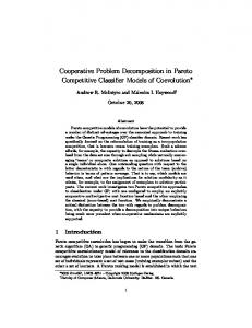
We have already applied POE in support of safety critical software developments [MHR07b, HMR07]. In those papers our focus was on the evaluation for safety of proposed candidate solution structures (i.e., partial solutions; architectures) early in development. In those papers, we attempted assurance-driven design for the first time and drew conclusions as to sequencing of steps that it required. The result is shown in Fig. 1 presented as a UML activity diagram. The activities in the figure include the following:
null problem
Context & Requirement Interpretation 1 Solution Interpretation & Expansion 2
Context and Requirement Interpretation to capture (increasing) knowledge and detail in the context and requirement of the problem (Activity 1; Context Interpretation was defined in Section 2.3);
Preliminary Safety Analysis 3
4
[PSA ok] solution development
Solution Intepretation and Expansion to structure the solution (or part thereof) according to a candidate architecture (Activity 2);
Figure 1. POSE Safety Process Pattern: to move towards the solution of a safety-critical problem, we first understand the problem better (Activity 1), use engineering judgement to determine a candidate solution architecture (Activity 2), then test the candidate for satisfaction of safety concerns, iterating if necessary.
Preliminary safety analysis (PSA) for early assessment of a candidate architecture (Activity 3). Although of no further concern to us in this paper, the techniques chosen for application during the PSA depend on the level of criticality of the system under design and may include Functional Failure Analysis (FFA) [SAE96], functional Fault Tree Analysis (FTA) [VGRH81], or the use of fully formal specification languages and logical proof (for instance, [Jac01a], as used in [MHR07b]). The level of criticality is determined by whether the system is safety critical (highest integrity required) or safety related (high integrity, but not as high as safety critical).
3.1
[not PSA ok]
3.2
Abstracting the POSE safety process pattern for general engineering use
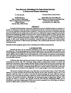
Although useful in the safety-critical software arena, the POSE safety pattern does not consider the needs of validation in the problem space, nor the roles of those who will perform that validation. In the new process illustrated in Figure 2, three areas are distinguished, the various activities are renamed, and one new activity and one new choice are added. The roles are our names for those whose role places them at the centre (the problem solver) or on the periphery (the validating stake-holders) of problem solving, described in more detail below. The activities are Partial Candidate Problem Exploration (renamed from Context and Requirement Interpretation in Figure 1); Partial Candidate Problem Validation, a new choice point, added (see below); (Partial) Candidate Solution Exploration; and Partial Candidate Solution Validation (again, see below). The partial nature of the candidates is so that early problem solving can focus on parts of the problem or solution, rather than the whole problem straight away. The relationship between the activities is shown in Figure 2. In the figure, there are roles of problem owning stakeholder(s), solution owning stake-holder(s), and problem solver, their respective scopes indicated by shading. A
The choice point
The choice point (labelled 4) in the figure depends on the outcome of the PSA, which determines whether the current candidate architecture is viable as the basis of a solution or whether, instead, we should backtrack the development to find another candidate solution or explore the problem further. In POE terms, choice point 4 needs to be made in the solution domain—it is a choice regarding the suitability of a solution architecture in a particular problem context—and so falls within the remit of a solution-owning stake-holder (a description of which will be given later). The artefacts upon which the choice is based are the, perhaps incomplete, solution against which the PSA was run. We have observed that it is not necessarily that case that a complete solution exists when the PSA is completed—one may, for instance, have only have chosen a solution architecture that is hoped 4
PCP validation 2
There are many familiar examples of problem owning stake-holders. These include, but are not limited to, those of customer (those that pay for a product), clients (those that pay for a service), regulator (those requiring safety, for instance), end-user (those who will use the product or service when commissioned). It is the problem owning stakeholders’ role to answer the question “Is this (partial) problem description valid for you?” Depending on the problemowning stake-holders’ responses, the problem solver may need to re-explore the problem (when the answer is ”No!”), or move on to try to find a (partial) solution (when the answer is “Yes”).
valid
invalid
(Partial) candidate problem exploration 1
(Partial) candidate solution (PCS) exploration 3
PCS validation reveals local problem flaw
invalid
PCS validation reveals past problem flaws
problem owning stake-holder is someone who role is to validate a (parital) candidate problem description that results from Partial Candidate Problem Exploration. It is important to note that the roles, as such, do not overlap.
PCS validation 4
valid
Problem owning stake-holder
Problem solver
Solution owning stake-holder
Figure 2. POE process Pattern: to move towards a partial solution to a general engineering problem, we first understand the problem better (1), reflecting our understanding of the problem through validation with the problem holding stake-holder (2); use engineering judgement to determine a candidate solution architecture (3), then test the candidate for satisfaction of safety concerns, iterating if necessary (4).
The role of the solution owning stake-holder(s) is to validate a candidate solution description, such as an architecture (a partial solution) or choice of component (i.e., something of complete functionality). The roles of solution owning stake-holders may be less familiar to the reader. They include, but are not limited to, a development house’s chief software architect—who knows which architectures their organisation uses in solutions, an oracle—who determines which of a number of features should be included in the next release, or a project manager—who needs to timebox particular activities; there are many other roles that fit solution owning stake-holder. It is the solution owning stakeholders’ role to answer the question “Is this (partial) solution description valid?” Depending on their response, the problem solver may need to re-explore the solution (when the answer is “No!”), move back to exploring this or a previous problem (when the answer is “No, but it throws new light on the problem!”), or moving on to the next problem stage (when the answer is “Yes!”).
3.3
Doing engineering design
Previously, we have focused on safety critical development in POSE, whence the justification obligation must satisfy the interested stake-holders that their concerns (similar in nature to those considered in [Jac01b]) about safety are discharged. In this paper, we map the same case study to the POE pattern, using to it for an opportunity to explain the various roles and artefacts. This will involve us in considering (and reconsidering) in detail the various roles. The justification obligations for the schemata underlying these exploration phases generate concerns that should be discharged as part of problem solving. A concern leads to a claim stated within a justification, the claim being that the concern is discharged by the development step. The justification will, eventually, contain arguments and evidence that the claim is valid so that the concerns is discharged. We say eventually because some concerns can only be discharged after the ramifications of a problem transformation are known which is, typically, later in the development tree. One particularly important concern is the step validity concern—for which the associated claim is a particular step is validatable—as it is the point of contact of the POE process with stake-holders external to the creative process of the problem solver; in particular, the problem and solution owning stake-holders. The step validity concern associated with a problem exploration step is dischargeable only with reference to the problem-owning stake-holder. The step validity concern associated with a solution exploration step
The role of problem solver is that of the person or persons that begins by trying to understand the problem and iterates towards a solution. As indicated by the upward pointing arrow that appears in the upper right of Figure 2, iteration is not always local: it is, for instance, possible that through the failed validation of a solution a previous problem description may be revealed as flawed, even if it has been validated by a problem-owning stake-holder and so invalid—problem-owning stake-holders make mistakes too! It is worth emphasising that we do not preclude communication between those that will perform the role of problem- or solution-owning stake-holder, or problem solver during the process of problem solving. Indeed, this would be a very sensible option—even if just to manage the expectations of the various stake-holders before the formal validation is conducted. 5
is dischargeable only with reference to the solution-owning stake-holder. It is the discharge of step validity concerns that require the problem solver to consult with stake-holders (although, of course, consultation with stake-holders may also take place in problem and/or solution exploration). On the other hand, like other concerns, the discharge of step validity concerns may be postponed. Depending on the criticality of a development, the risk exposed by such a postponement may be unacceptable—given that a problemor solution-owning stake-holder has not validated a partial problem or solution candidate, the problem solver may be solving the wrong problem with incorrect solution technologies, or both. In this case, the future development is based on an assumption of validity. The commitment of developmental resources on this assumption is the source of the risk, although it may be more or less mitigated by problem solver experience. Of course, even if the risk is managed by discharging the step validity concern, there may be secondary risks, such as the a problem-owning stake-holder being incorrect in their validation. It may therefore be important, as part of the justification for the development step to record the explicit instance of step validity concern discharge so that it is traceable; the recording of concern discharges are properly a part of all POE steps.
4
During a problem exploration, the problem solver will work he following problem: out Defence Systemcon , Dispenser Unitfire,sel , air Aircraft Status System , P1 : fire,sel Pilotok , Decoy Controllercon,out,air,ok fire,sel ` Rcon,out,air,ok
The justification obligation for an interpretation schema application requires us to justify a newly provided description over the existing one. Here is the (collated) justification for all intepretation transformations from Pnull to P1 which add knowledge of the problem and its parts. S TEP 1: Application of C ONTEXT AND R EQUIREMENT I NTERPRETATION to problem Pnull J USTIFICATION J1 : The identified requirement, domains and their relevant properties are summarised below: Name
Case study
The case study is a real development, performed by the authors and Derek Mannering of General Dynamics UK Ltd, based on systems flying in real aircraft. The case study is abbreviated only in the sense that some detail has been removed: it retains all essential complexity; more detail, and its original context, can be found in [MHR07b, HMR07, MHR07a, MHR07c]. It concerns the development of the Decoy Controller component of a defensive aids system whose role is to control the release of decoy flares providing defence against incoming missile attack. In POE, to record that we have something that is deserving of the resources that will be used in solving a problem we give a marker for the start of the problem solving process: all problem solving starts from the null problem—the problem of which we know nothing other than its existence: Pnull :
Description
Defence System
The computer responsible for controlling and orchestrating all defensive aids on the aircraft
Dispenser Unit
Mechanical device for releasing decoy flares used as defence against incoming missile attack. It has number of different flare types, and includes a safety pin that, when in place, prevents flares from being released
Aircraft Status System
The system which monitors the status of certain key aircraft parameters, including whether the aircraft is in the air
Pilot
The pilot, who can signal the controller that flare release should be allowed
Decoy Controller
null
R
The conjunction of: Ra : On receiving a con command from Defence System, Decoy Controller shall obtain the selected flare type information from the relevant field in con, for use in its sel message to the Dispenser Unit to control flare selection. Rb : Decoy Controller shall issue a fire command only on receiving a con command from Defence System. This shall be the only way in which a flare can be released.
W : null, S : null ` R : null
null is used as the description for W, R and S to indicate that nothing is known about them. Moving from the null problem to that of the case study is a first problem exploration step. The details of the problem exploration follow.
Rc : Decoy Controller shall cause a flare to be released by issuing a fire command to the Dispenser Unit, which will fire the selected flare. continued
4.1
Initial Problem Exploration
6
Name
C ONCERN: Step Validity S TATUS: Pending
Description Rd : Decoy Controller shall only issue a fire command if its interlocks are satisfied, i.e. aircraft is in air (air = yes), safety pin has been removed (out = yes) and pilot has issued an allow a release command (ok = yes).
Of course, the descriptions at which we have arrived through the problem exploration step have not been arrived at in a vacuum: as shown in the argument and evidence supporting a claim of step validity, they were arrived at only after careful work predicated on discussion with the customer and reference to best practice. The step validity concern should, then, be easy to discharge by appeal the problemowning stake-holder (in this case the customer for the system), and in a real development this should be done unless the risk of not doing it acceptable. So that we can progress towards solution exploration, we will assume that the validity concern is discharged in this case so that we may write:
RS : Decoy Controller shall mitigate H1 and H2 , where H1 is the inadvertent firing of decoy flare on ground. Safety Target: safety critical, 10−7 fpfh (where fpfh is ‘failures per flight hour’); and H2 is the inadvertent firing of decoy flare in air. Safety Target: safety critical, 10−7 fpfh. P HENOMENA: Phenomena and their control and sharing (see P1 ) are known from the existing system components as: Name
Description
fire
Command to release the selected flare type
sel
Command to select flare type
out
Pin status: out = yes when pin removed
con
Command to select and release a flare type
air
Aircraft status: air = yes when aircraft airborne
ok
Pilot intention: ok = yes then allow release
S TEP 1: Sign-off of C ONTEXT AND R EQUIREMENT I NTERPRETATION to problem Pnull C ONCERN: Step Validity S TATUS: Signed-off
C ONCERN: Interpretation validity S TATUS: Discharged C LAIM:
D ETAILS: The descriptions used were arrived at after a successful bid to tender, when the mechanical outline, approximate weight and power envelope of the system were established. Subsequent communications with the customer were used to clarify the requirements and properties of the system environment. The remainder of the system was designed in response to the post bid revised customer requirements including their allocation to software and hardware as appropriate
The interpretations are valid
A RGUMENT & E VIDENCE: The choice of domains follows from the aircraft level safety analysis and the required choice of interlocks. The Defence System, Dispenser Unit, Aircraft Status System are existing components of the avionics system, with well-known properties (that could be validated through direct inspection). The Pilot is trained to follow protocol rigorously. The customer requirement was provided as an input to the developer team. Hazard H1 and H2 came from an aircraft level safety analysis which allocated safety requirements to the main aircraft systems, including the Decoy Controller. Hazards H1 and H2 have both systematic (safety related) and probabilistic components. To counter these hazards, the following safety interlocks were required as input to the Decoy Controller to provide safety protection: an input from the pilot indicating whether the release should be allowed; an input indicating whether the aircraft is in the air; and an input indicating whether the safety pin, present when the aircraft is on the ground, is in place. The expected behaviour is that flare release should be inhibited if any of the following conditions hold: a) the pilot disallows flares; b) the aircraft is not in the air; or c) the safety pin has not been removed. These interlocks provide extra assurance for hazard H1 , but not for H2 . Therefore, the safety task is to demonstrate that H2 can be satisfied, with the knowledge that if H2 can be satisfied, then so can H1 .
S IGNATORY:
Customer
In general, recording who, where and when the validity concern was discharged would also be sensible as would authentication of—perhaps a signature—of the validator, for traceability reasons.
4.2
Solution Interpretation and Expansion
Given our validated problem statement, we may move towards exploration of the solution. An AStruct (short for Architectural Structure) is used to add structure to a solution domain, through an application of SOLUTION INTERPRETATION. An AStruct combines, in a given topology, a number of known solution components5 5 There are also constraints on the phenomena sets, which we omit here for brevity; the reader is referred to [HRJ07] for the full definition.
7
(the Ci below) with solution components yet to be found (the Sj below). Its general form is:
Name DM
AStructName[C1 , ..., Cm ](S1 , ..., Sn ) with AStructName the AStruct name. Once the solution is interpreted by providing and justifying an AStruct, SOLU TION EXPANSION generates premise problems by moving the already known components Ci to the environment— expanding the problem context—whilst simultaneously refocussing the problem to be that of finding the solution components Sj that remain to be designed. The requirement and context of the original problem is propagated to all subproblems. A particular case, which is relevant to our case study, is when there is only one component to be found, that is, the AStruct has the following form:
[S OLUTION E XPANSION]
DS!{con}
Collects together the interlock inputs and passes their status to Safety Controller (int)
Safety Controller
null
Name fire? int
The new phenomena introduced by the archi-
Description Command to release the selected flare type Status of combined interlocks
C ONCERN: Sound engineering S TATUS: Discharged
fire int sel,fire? DecoyContAS[IIok,air,out , DMcon ](Safety Controllerint,fire? )
which includes two extant components, II and DM and one to be found component Safety Controller. Therefore, a subsequent expansion leads to problem:
C LAIM: The choice of candidate solution architecture exhibits sound safety engineering judgement A RGUMENT & E VIDENCE: The architecture is chosen to minimise the number and extent of the safety related functions, localising them to simple, distinct blocks in accordance with best practice.
out Defence Systemcon , Dispenser Unitfire,sel , air ok Aircraft Status System , Pilot , P2 : fire int sel,fire? IIok,air,out , DMcon , Safety Controllerint,fire? fire,fire?,sel ` Rcon,out,air,ok
C ONCERN: Candidate solution validity S TATUS: Pending
Here is the combined development step:
C LAIM: The chosen solution architecture does not prevent the satisfaction of R.
S TEP 2:
Application of S OLUTION I NTERPRETATION AND E XPANSION to problem P1
We note that, due to the fact that the solution exploration is incomplete as yet, the pending validity concern will not need to be discharged until after the feasibility concern. Of course, discussions that might arise due to addressing the validity concern may inform the PSA; however, there is no risk associated with the validity concern until a point when the decision to commit further resources to the development is required; the first point at which this holds is after we know whether the current architecture is the basis of a technically feasible solution or not.
J USTIFICATION J2 : The identified architecture, its components and relevant properties are summarised in the table below:
Decoy Controller
MB
II
P HENOMENA: tecture are:
In the case study, the following AStruct encodes the initial candidate architecture chosen for the Decoy Controller:
Name
uP
DM!{sel}
In this case expansion only generates one premise problem as follows:
W, S : AStructName[C1 , ..., Cm ](S) ` R
A microcontroller used to decode con messages from Defence System and when appropriate issue a fire command request, fire?, to the Safety Controller. In the schematic: the message buffer MB holds the received control message con; the micro-controller uP decodes it to extract: a) a fire command request (leading to fire?), and b) the selected flare type (leading to sel). DM!{fire?}
AStructName[C1 , ..., Cm ](S)
W, C1 , ..., Cm , S:null ` R
Description
Description sel,fire? int DecoyContAS[IIok,air,out , DMcon ](Saf fire ety Controllerint,fire? )
continued
8
4.3
Preliminary Safety Analysis
Table 1. FFA Summary for Safety Controller Id F1 F2
The justification of the previous transformation step is incomplete: the feasibility concern remains to be discharged. The related claim is that the chosen architecture candidate should not prevent an adequately safe solution and yet, as we shall argue, it does prevent an adequately safe solution. In the worst case, to continue the design without checking feasibility uncovers the risk that the final product cannot be argued safe. Traditionally, such risks are mitigated through over-engineering of the solution, but this typically adds to the development cost. Here, the risk is managed through a Preliminary Safety Analysis (PSA), eagerly applied in the attempt to discharge the feasibility concern. The goal of a PSA is to: (a) confirm the relevance of hazards allocated by the system level hazard analysis; (b) identify any further hazards to be added to the list; and (c) validate the architecture against the safety targets associated with the identified relevant hazards. Many techniques can be applied to perform a PSA. In [MHR07c] we used a combination of mathematical proof, Functional Failure Analysis (FFA) [SAE96] and functional Fault Tree Analysis (FTA) [VGRH81]. Note that PSA is not a POSE transformation per se (no POSE schema defines a PSA). Instead it is a technique which we use to discharge one of the concerns in the justification obligation for S OLUTION I NTERPRETATION.
F3 F4 F5
Failure Md No fire? fire? at wrong time fire? when not required Intermittent fire? Continuous fire?
Effect Release inhibited Inadvertent release
Haz No Yes
Inadvertent release
Yes
Could inhibit release Inadvertent release
No Yes
safety analysis indicates that fire? needs to have a safety involved (not critical) integrity. This can only be achieved with the existing design by upgrading all of the design to be safety involved. That is, by assigning fire? to the uP, we require that all uP functionality must be of fire?s required safety integrity, including much of the uPs functionality (timing, BIT, etc.) that is not safety-related. Further, any updates to the uP software have to satisfy the safety involved integrity. To make the uP safety-involved is not possible. The conclusion of the PSA is that the selected DM component, hence the architecture, is not a suitable basis for the design—no adequate solution can be derived from its parametrisation, hence the feasibility concern cannot be discharged.
As there is a concern that is undischargeable, including the step validity is not appropriate.
4.4 Application of S OLUTION I NTERPRETATION AND E XPANSION to problem P1 (cont’d)
Backtracking the development
S TEP 2:
The failed PSA causes the iteration of the POSE safety process, i.e., the development is backtracked to P1 and a second candidate architecture chosen, informed by what we learned from the failed feasibility claim. The second iteration of the POSE process is similar to the first: although there is new information associated with the revised architecture, the remainder of the transformations may be carried across from the first iteration without change, simplifying this second (and any subsequent) iteration. The second candidate architecture differs from the original in that we replace DM with higher integrity component DM 0 . Here is the development step:
C ONCERN: Candidate solution validity S TATUS: Undischargeable C LAIM: The chosen solution architecture does not prevent the satisfaction of R. This claim does not hold. A RGUMENT & E VIDENCE: We applied FFA to each architectural component in turn. The significant results6 from applying FFA to the DM are shown in Table 1, where three problem cases were identified: F2, F3 and F5, with ‘Yes’ in the Hazard column. A functional FTA applied to DM and using the three FFA problem cases F2, F3 and F5, indicates that a failure in uP (systematic or probabilistic) could result in the fire? failing on. The Pilot’s allow input provides some mitigation, but as soon as this is set (ok = yes) a flare will be released, which is undesirable behaviour. In other words, with this architecture, H2 is only protected by the Pilot’s allow input. If fire? failed on, then as soon as the Pilot indicated an intention to allow flare release, by selecting the switch, then the flare would be released, which is not the design intention. Therefore the
S TEP 2.1: Re-application of S OLUTION I NTERPRETATION AND E XPANSION to P1 J USTIFICATION J20 : The newly identified architecture, its components and relevant properties are summarised below (where they differ from J2 ): Name Decoy Controller
6 There
is insufficient space to present the full PSA, and so we summarise only its main elements to demonstrate the process followed.
Description 0sel,fire? int DecoyContAS[IIok,air,out , DMcon ](Saf fire ety Controllerint,fire? )
continued
9
Name DM
0
development organisation to make use of it, as well as confirming that the arguments underlying the PSA are sound. We arrive at:
Description A microcontroller used to decode con messages from Defence System and when appropriate issue a fire command request, fire?, to the Safety Controller. In the schematic: the message buffer MB holds the received control message con; the micro-controller uP decodes it to extract the selected flare type (leading to sel); the FPGA (a Field-Programmable Gate Array, [HH05]) component decodes it to extract a fire command request (leading to fire?). DM’!{fire?}
S TEP 2.1: Sign-off of re-application of S OLUTION I NTERPRETATION AND E XPANSION to P1
C ONCERN: Step Validity S TATUS: Signed-off
FPGA MB
A RGUMENT & E VIDENCE: The current solution is not computationally complete so no testing of a computationally complete product was possible. However, it is the assessment of the safety authority that the reasoning underlying the PSA that justifies this choice of architecture is valid and sound.
DS!{con}
uP DM’!{sel}
Safety Controller I NCLUDES:
null
S IGNATORY:
Safety Authority
Includes J2 , with alterations as discussed below.
C ONCERN: Sound engineering S TATUS: Discharged
Note that we do not yet have a working solution; rather we have an architecture for a solution consisting of a microprocessor, an FPGA and a Message Buffer. The discharge of the validity concern does not remove all risk in proceeding with the development. For instance, the risk that the development will again need to be backtracked to find a third candidate solution remains. However, there risk that the solution-owning stake-holder will not sign off a solution based on this architecture has been shared (or transferred) to that solution-owning stake-holder.
C LAIM: The choice of candidate solution architecture exhibits sound safety engineering judgement A RGUMENT & E VIDENCE: The chosen architecture is similar to the previous one (see J2 ) except that as a result of the PSA we require the fire? signal to be safety involved (but not safety critical) so that to allow the overall architecture to satisfy its safety target. We do this by taking the safety involved functions out of the uP component and route them through a separate high integrity path. Details omitted for brevity.
5
C ONCERN: Candidate solution validity S TATUS: Discharged
Discussion
The POE notion of problem requires a separation of context, requirement and solution, with explicit descriptions of what is given, what is required and what is designed. This improves the traceability of artefacts and their relation, as well as exposing all assumptions to scrutiny and validation. That all descriptions are generated through problem transformation forces the inclusion of an explicit justification that such assumptions are realistic and reasonable. In particular, safety requirements are justified as valid, are fully traceable with respect to the designed system, and evidence of their satisfaction is provided by the adequacy argument of a completed POE development tree. We have shown (a) how (partial) problem and solution validation are used to manage developmental risk and (b) have shown how an assurance case can be constructed alongside the development of a product. That product and assurance argument development are co-designed is a fundamental possibility under POE: no transformation should occur without appropriate justification (although such justification may not be immediately
C LAIM: The chosen solution architecture does not prevent the satisfaction of R. A RGUMENT & E VIDENCE: Omitted, for brevity
As a result of this step, we arrive at: out Defence Systemcon , Dispenser Unitfire,sel , air ok Aircraft Status System , Pilot , P02 : fire int 0sel,fire? IIok,air,out , DMcon , Safety Controllerint,fire? ` Rfire,fire?,sel con,out,air,ok
Here, to manage risk, we much discharge the validity concern with reference to a solution-owning stake-holder, for instance the safety authority, who will be able to decide whether the chosen architecture satisfied development requirements such as availability—whether the architecture is used within the development body—and whether sufficient experience exists or can be made to exist within the 10
available, requiring some exploratory development to be done first). On the other hand, development risks can be taken by tentative transformation which are not completely justified: in such cases concerns can be stated as suspended justification obligations to be discharged later on in the process. This adds the flexibility of trying out solutions, while still retaining the rigour of development and clearly identifying points where backtracking may occur. Finally, POE defines a clear formal structure in which the various elements of evidence fit, that is whether they are associated with the distinguished parts of a development problem or the justifications of the transformation applied to solve it. This provides a fundamental clarification of the type of evidence provided and reasoning applied. Moreover, that the form of justification is not prescribed under POE signifies that all required forms of reasoning can be accommodated, from deductive to judgemental, within a single development.
package router control problem. IEEE Trans. Software Eng., 2008. doi:10.1109/TSE.2007.70769.
Adrian Hilton and Jon G. Hall. Developing critical systems with PLD components. In Tiziana Margaria and Mieke Massink, editors, FMICS ’05: Proceedings of the 10th international workshop on Formal methods for industrial critical systems, pages 72–79, New York, NY, USA, 2005. ACM Press.
[HMR07]
Jon G. Hall, Derek Mannering, and Lucia Rapanotti. Arguing safety with problem oriented software engineering. In 10th IEEE International Symposium on High Assurance System Engineering (HASE), Dallas, Texas, 2007.
[HRJ07]
Jon G. Hall, Lucia Rapanotti, and Michael Jackson. Problem oriented software engineering: A design-theoretic framework for software engineering. In Proceedings of 5th IEEE International Conference on Software Engineering and Formal Methods, pages 15–24. IEEE Computer Society Press, 2007. doi:10.1109/SEFM.2007.29.
[HRJ08]
Jon G. Hall, Lucia Rapanotti, and Michael Jackson. Problem-oriented software engineering: solving the
Michael A. Jackson. Problem Frames: Analyzing and Structuring Software Development Problems. Addison-Wesley Publishing Company, 1st edition, 2001.
[MHR07c] Derek Mannering, Jon G. Hall, and Lucia Rapanotti. Towards normal design for safety-critical systems. In M. B. Dwyer and A. Lopes, editors, Proceedings of ETAPS Fundamental Approaches to Software Engineering (FASE) ’07, volume 4422 of Lecture Notes in Computer Science, pages 398–411. Springer Verlag Berlin Heidelberg, 2007.
References
[HH05]
[Jac01b]
[MHR07b] Derek Mannering, Jon G. Hall, and Lucia Rapanotti. Safety process improvement with POSE & Alloy. In Francesca Saglietti and Norbert Oster, editors, Proceedings of The 26th International Conference on Computer Safety, Reliability and Security (SAFECOMP 2007), volume 4680 of Lecture Notes in Computer Science, pages 252–257, Nuremberg, Germany, September 2007. Springer-Verlag.
We acknowledge the financial support of IBM and of SE Validation Limited, in particular Colin Brain for his many comments and insights. We also thank Derek Mannering whose work first instantiated the POE process pattern, and our colleagues in the Centre for Research in Computing at The Open University, particularly Michael Jackson.
Engineering Council of South Africa Standards and Procedures System Definition of Terms to Support the ECSA Standards and Procedures System.
Daniel Jackson. Micromodels of software: Lightweight modelling and analysis with alloy. Software Design Group MIT Lab for Computer Science. http://alloy.mit.edu/reference-manual.pdf, 2001.
[MHR07a] Derek Mannering, Jon G. Hall, and Lucia Rapanotti. Safety process improvement: Early analysis and justification. In Proceedings of the 2nd Institution of Engineering and Technology Conference on System Safety 2007, 2007.
Acknowledgments
[EDD]
[Jac01a]
[Pel99]
Francis Jeffry Pelletier. A Brief History of Natural Deduction. History and Philosophy of Logic, 20:1– 31, 1999.
[SAE96]
SAE. ARP4761: Guidelines and Methods for Conducting the Safety Assessment Process on Civil Airborne Systems and Equipment, 1996.
[VGRH81] W. Vesely, F. Goldberg, N. Roberts, and D. Haasl. Fault Tree Handbook, volume NUREG-0492. U.S. Nuclear Regulatory Commission, 1981.
11