Preliminary application of codes to VVER severe accident sequence simulations in ... transmit the ASTEC code to NSI RRC KI for application to VVER reactors.
SESSION 7. Code application and PSA methodologies. Paper No 1
ASTEC Code Validation and Application to Safety of NPPs with VVER Yu. Zvonarev, M. Budaev, V. Kobzar, A. Volchek Nuclear Safety Institute of Russian Research Centre “Kurchatov Institute”, Moscow (RU) SUMMARY ASTEC is computer codes allowing to analyze severe accidents in LWRs. The ASTEC integral code, commonly developed by IRSN (France) and GRS (Germany), is intended for prediction a whole severe accident sequence from the initiating event to Fission Product release out of the containment. The code applicability to VVER is a clear common IRSNGRS objective. The current work in collaboration between IRSN and NSI RRC KI (Russia) aims at reaching this objective. Several actions supporting ASTEC code application to VVER have been initiated: Validation of code on experiments specific to VVER conditions; Preliminary application of codes to VVER severe accident sequence simulations in order to define the necessary code improvements; Development and implementation into code of models specific to VVER safety systems; Performing of benchmark calculations between ASTEC and ICARE/CATHARE codes for LOCA sequences on VVER-1000. The next stages of the collaboration will consist to draw the modelling specifications of VVER safety systems, and in parallel to work on validation and reactor applications of the next versions of ASTEC code. A.
INTRODUCTION
The objective of the Nuclear Safety Institute of Russian Research Centre Kurchatov Institute (NSI RRC KI) R&D program on severe accident is to get a sufficient understanding of all major phenomena occurring in case of a severe accident in VVER. With this objective, NSI RRC KI is conducting experimental programs and code developments in the related fields. Regarding computer code development, NSI RRC KI is developing a severe accident RATEG/SVECHA/GEFEST code in cooperation with other Russian Institutes and simultaneously using existing foreign codes for safety analysis of the NPPs with VVER. The integral code ASTEC has been developed with the aim to get a fast running code for the simulation of the total sequences of severe accidents in LWR from the initiating event up to the possible fission product release to the environment. The version ASTEC V1.0 rev 2 code (Ref. [1]) consists of the following modules: − CESAR for RCS 2-phase thermalhydraulics during the front-end phase and the degradation phase; − DIVA for core degradation including late phase phenomena (molten pool, corium slump to lower head, corium in lower head) and vessel failure; − ELSA for release of FP from fuel rods and debris and of materials from control rods, using a semi-empirical approach; − SOPHAEROS for FP vapor and aerosol transport in RCS; − RUPUICUV for corium discharge from vessel to cavity with cavity pressurisation and potential direct containment heating; − WEX for molten core-corium interaction in the cavity; − CPA for multi-compartment containment simulation, including thermal-hydraulics, hydrogen combustion, and aerosol and FP behaviour; The first European Review Meeting on Severe Accident Research (ERMSAR-2005) Aix-en-Provence, France, 14-16 November 2005
SESSION 7. Code application and PSA methodologies. Paper No 1
− IODE for iodine behaviour in the containment (sump and gas phase); − ISODOP for decay heat and activity of FP and actinide isotopes in core, RCS, containment and environment; − SYSINT for management of safety systems (spray, high and low pressure injection, accumulators…). In the frame of the collaboration between NSI RRC KI and IRSN it was decided to transmit the ASTEC code to NSI RRC KI for application to VVER reactors. B.
WORK PROGRAMME Several actions supporting code applications to VVER have been performed: − Validation of ASTEC code on experiments specific to VVER conditions; − Preliminary application of ASTEC code to VVER severe accident sequence simulations in order to emphasize the necessary code improvements; − Preparation to development of safety system models specific to VVER.
The first steps in above-mentioned directions have been made. A specific VVER validation matrix was developed, which includes a set of integral tests on investigation of all basic phases of the severe accident sequence (from core degradation till thermalhydraulics of the steam-gas atmosphere in containment). The ASTEC code validation against different tests has been started. The application of ASTEC code to some hypothetical severe accident sequences and to some real incidents on the NPPs with VVER has been performed. The next stages of the collaboration will consist to draw the specifications of VVER safety systems modelling, and in parallel to work on validation and reactor applications of the next versions of ASTEC code. C.
MAIN ACHIEVEMENTS
This section will describe the achivement made in the wotk program areas in term of code validation on the test results specific to VVER, code application to hypothetical severe accident sequences on VVER and simulation of the real incidents on the NPPs with VVER. C.1 Validation of the ASTEC Code on VVER Experiments In order to apply ASTEC code to safety analysis of NPPs with VVER-type reactors it is necessary to perform the validation of codes on experiments specific to VVER conditions. The design of ASTEC code allows to run any module in a stand-alone mode. This mode allows to perform the module validation on separate-effect or coupled-effect experiments. The validation matrix with selected VVER-specific experiments is presented below (Table I). It includes all main stages of the severe accident progression such as core dryout and degradation, molten corium formation, core blockage, corium molten pool behaviour in the reactor lower plenum, molten corium interaction with the concrete in the reactor cavity, hydrogen distribution in the containment, hydrogen combustion… The application of ASTEC code to this validation matrix is in progress now. Below some results of ASTEC code validation against HD (Hydrogen Distribution) tests are presented. The first European Review Meeting on Severe Accident Research (ERMSAR-2005) Aix-en-Provence, France, 14-16 November 2005
SESSION 7. Code application and PSA methodologies. Paper No 1
The CPA module included into the ASTEC code simulates all basic processes taking place in the NPP containment during the accident, including the processes of hydrogen distribution. This section presents the results of the CPA module validation against the HD tests on hydrogen distribution in a system of connected cells simulating the major compartments in the VVER-1000 containment. The vessel representing a vertical cylinder 5.48 m high, 2.2 m in diameter and 20 m3 in volume is the basic part of the experimental facility. Partitions are placed inside the vessel dividing it into 9 cells. The volumes of the cells are proportional to those of the major compartments in the containment of the NPP with the VVER-1000 reactor; the same for the height marks in the cells of the test facility, and the cross-section areas for the junctions connecting cells of the test facility. The general view of the test HD facility is shown below (Figure 1). Table I: Validation matrix specific to VVER Test
Main features of the experiment
CORA-W1, CORA-W2 CODEX-2, CODEX-B4C RASPLAV AW-200-4
VVER-type reactor fuel element bundle degradation and impact of B4C control rod on the fuel bundle degradation VVER-type reactor fuel element bundle high temperature behaviour, control rod degradation and B4C oxidation
BETA V7.1
Molten corium interaction with serpentine concrete, which used for fabrication of upper layer of the VVER-1000 reactor cavity
ACE L4
Molten corium interaction with two-layered serpentine/lime concrete basement
HD-3, HD-6, HD-8, HD-9
Hydrogen distribution in the compartments of the VVER-1000 containment mock-up
RUT Sth-6, Sth-9
Combustion of hydrogen-air-steam composition of components
Molten corium interaction with reactor lower head
mixtures
with
different
Experiments with hydrogen feeding into different locations of the test facility and with different rates of hydrogen feeding were performed. 11 tests altogether were performed. To validate the CPA module, four experiments HD-3, HD-6, HD-8, and HD-9 were selected in which the locations of hydrogen feeding correspond to the most typical locations of hydrogen income into the VVER-1000 containment during severe accidents. The HD-3 and HD-6 experiments modelled hydrogen income into one of the steam-generator compartments through the rupture of the primary circuit pipe line; the HD-8 experiment modelled hydrogen generation in the reactor cavity in the course of molten corium interaction with concrete; the HD-9 experiment modelled hydrogen income into the space under containment dome through the pressurizer valve. The simulation of selected experiments was performed in several stages using nodalization schemes containing a different number of nodes. The initial nodalization scheme The first European Review Meeting on Severe Accident Research (ERMSAR-2005) Aix-en-Provence, France, 14-16 November 2005
SESSION 7. Code application and PSA methodologies. Paper No 1
consisted of 9 nodes. Each node of this scheme corresponded to the individual cell of the test facility. A further improvement of the nodalization scheme is associated with the improvement of modelling hydrogen upward flows above the hydrogen source that were observed in the experiments. To this end, an additional partitioning of calculation nodes located above the hydrogen source was performed. Thus improved nodalization schemes were used containing from 23 up to 39 nodes depending on the location of hydrogen feeding in the modelled experiments.
The facility cells V1-V9 correspond to the following VVER-1000 containment compartments: Cells V1 and V2 – the steam generator compartments; Cells V3 and V4 – the compartments with ECCS basic equipment; Cell V5 – dome part of the containment; Cell V6 – the compartments for the maintenance of the auxiliary equipment in the containment lower part; Cell V7 – the rectangular tank with one of the side walls lacking, corresponds to the terminal compartments in the lower part of the containment; Cell V8 and V9 – the compartments with fans and to corridors.
Figure 1: General view of the hydrogen distribution test facility The comparison of calculated and measured hydrogen concentrations revealed a trend of improvement for the coincidence of results from the 9-node scheme to the improved one with a higher number of nodes (23 – 39). For the case of 39-node nodalization scheme, a satisfactory agreement between the calculated values of hydrogen concentrations and the measured ones may be noted (Figure 2). At the period of hydrogen feeding into the facility, the calculation satisfactorily simulates the rate of concentration increase and the variation in concentration along the cell height. However, it should be noted that the increase in number of nodes of used nodalization schemes results in the increase of CPU time. Thus, for calculating the HD-6 experiment with the CPA module on a DEC Alpha workstation employing 9-, 23-, and 39-node nodalization schemes, CPU time was 150, 460, and 930 seconds, respectively. On the whole, in the course of modelling the HD-3, HD-6, HD-8, and HD-9 experiments employing the improved nodalization schemes, quite satisfactory results were obtained.
The first European Review Meeting on Severe Accident Research (ERMSAR-2005) Aix-en-Provence, France, 14-16 November 2005
SESSION 7. Code application and PSA methodologies. Paper No 1
A good agreement of the calculated values of hydrogen concentrations with the experimental ones for the nodes located at the middle level of the test facility is observed in the experiments HD-3 and HD-6 in which the hydrogen source was located in the middle part of the model height (the cell V1). The discrepancy between calculated and experimental concentrations does not exceed 0.5% (absolute). A good intermixing of hydrogenous medium is observed throughout all cells of the test facility in the experiment HD-8 in which the hydrogen source was located in the bottom part of the test facility (the cell V6). The calculated values of the hydrogen concentrations are in a quite satisfactory agreement with the experimental values. The discrepancy of results does not exceed 0.5% (absolute).
Hydrogen concentration (% vol.)
6
5
V5
Calculated H=0.86 m Measured H=1.40 m Measured H=0.00 m
4
3
2
1
0
V5
0
20
40
60
80
Time (min)
Hydrogen Concentration Sensor Place of Hydrogen Feeding
Figure 2: ASTEC validation against HD-3 test. Hydrogen concentration versus time in the cell V5 The conclusion about the agreement of the results obtained by the CPA module with the experimental data was based on the results of the calculations obtained on employing the improved nodalization schemes. Thus, on the basis of the satisfactory validation results, the applicability of the CPA module of the ASTEC code for the study of the hydrogen distribution in the containment compartments may be stated for analysis of the progress of severe accidents in the NPP with the VVER-1000. C.2 Application of the ASTEC Code to Hypothetical Severe Accidents on a VVER The ASTEC code was applied to simulation of some hypothetical severe accidents on the VVER-1000. Among them are the following: • Large break LOCA with double-ended rupture of the reactor coolant system pipe (D=850 mm) and failure of all active parts of ECCS. The first European Review Meeting on Severe Accident Research (ERMSAR-2005) Aix-en-Provence, France, 14-16 November 2005
SESSION 7. Code application and PSA methodologies. Paper No 1
• •
Middle break LOCA with rupture of the hydro-accumulator pipe (D=279 mm) and failure of all active parts of ECCS. Small break LOCA with break (D=70 mm) in the cold leg of the reactor coolant system and failure of all active parts of ECCS.
Additionally some benchmark calculations were performed between ASTEC and ICARE/CATHARE codes for large break and small break LOCA sequences on the VVER1000. A good enough agreement between timing of main events of severe accident sequences predicted by different codes was obtained. At the same time large uncertainties in amount of corium formation and in its oxidation were revealed while corium oxidation is a key factor affecting the late hydrogen release and the corium metal-oxide composition. Obtained results will allow to extend ASTEC code capabilities in respect to analyses of severe accidents on the VVER. As an example some pictures below illustrate the benchmark calculation results between ASTEC and ICARE/CATHARE codes for large break LOCA on the VVER-1000. In accordance with both ASTEC and ICARE/CATHARE simulations the major part of water in the primary circuit is boiled off just after large break opening. In the primary circuit, only 5% of the initial water is remaining 15 s after the onset of the accident. The water injection from SITs increases the amount of water up to ~45% of initial mass at 90 s. After the water injection period, the mass of water in the core gradually decreases and water level lowers (Figure 3). 4
Level (m)
Core top ASTEC V1
3
I/C V1
2
1
Core bottom
0 0
500
1000
1500
2000
2500
3000
Time (s)
Figure 3: Collapsed Water Level in the Core As the water level in the core decreases the fuel rod cladding temperature begins its increase in the upper part of the core. In about 10-15 minutes after the onset of the accident the both of codes predict beginning of the fuel rod cladding temperature increase in the middle part of the core at elevation of 1.9 m (Figure 4). It can be seen that the ASTEC prediction is very close to the ICARE/CATHARE one.
The first European Review Meeting on Severe Accident Research (ERMSAR-2005) Aix-en-Provence, France, 14-16 November 2005
Temperature (K)
SESSION 7. Code application and PSA methodologies. Paper No 1
3600
ASTEC V1
3000
I/C V1
2400
1800
1200
600
0 0
500
1000
1500
2000
2500
Time (s)
Figure 4: Fuel Rod Cladding Temperature Evolutions at the Core at the Middle of Radial Ring Number 5 (R=1.5 m, Z=1.9 m) The final state of the VVER-1000 facility at time 1915 s (This time is the final time for ASTEC calculation) after the onset of the accident is shown in the color diagram below (Figure 5). It illustrates cladding melting, melt relocation and molten pool formation. Corium flows down and evaporates remaining water in the reactor lower plenum. The calculation results obtained by ASTEC and ICARE/CATHARE codes are consistent with each other.
Figure 5: Core Degradation at Time 1915 s Predicted by ASTEC and ICARE/CATHARE Codes
The first European Review Meeting on Severe Accident Research (ERMSAR-2005) Aix-en-Provence, France, 14-16 November 2005
SESSION 7. Code application and PSA methodologies. Paper No 1
C.3 Application of the ASTEC Code to Real Incidents on a VVER Application of the ASTEC code to the real incidents on the VVER is an important part of the work on European code adaptation to the VVER. Two real incidents were simulated: the Incident on Kalinin NPP with VVER-1000 and the Incident on Paks NPP with VVER-440. The Incident on Kalinin NPP Experimental data obtained at operating NPPs are a reliable base for assessment of computer codes applied to analysis of NPP operation and safety. One of the most important parameters to be controlled at Russian designed NPP with VVER type reactors is a water level position in steam generators. When it exceeds the maximum permitted value, humidity of vapor entering turbine will be increased. If the water level will decrease heat exchange will be degraded. In July 1996 at Unit-1 Kalinin NPP in Russia, occurred the activation of the 1-st kind emergency protection caused by decreasing of the steam generator No 4 water level during unit operation with 11-th fuel cycle. The feedwater flowrate to the SG sharply decreased caused by the failure of the check valve in the SG feedwater supply pipeline. The plant data collected during the incident by plant data acquisition and in-vessel monitoring systems were used for preparation of the specification for validation of CESAR module of the ASTEC code.
-
The following measured parameters of VVER-1000 during the transient were used. • Primary circuit parameters: Reactor power; Primary circuit pressure; Reactor vessel inlet/outlet coolant temperature; Main circulation pumps head; Reactor vessel pressure drop; Steam generators pressure drop; Pressurizer collapsed water level. • Secondary circuit parameters: Steam generators pressure; Steam generators collapsed water level; Feedwater mass flowrate; Feedwater temperature.
The sharp decrease of the feedwater flowrate to the SG-4 was caused by the failure of the feedwater pipeline check valve. This moment is assumed to be the start of the transient. The transient has been defined by the operation of the following regulators: ARM, EGSR, ROM. After check valve failure a sharp decrease of the feedwater flowrate to the SG-4 occurred. Eight seconds later the water level in the SG-4 began to decrease and at τ = 45 sec, the set point for MCP-4 switch-off was reached. ARM stops its management of the reactor power after switching-off MCP-4. ROM was moving the 10-th control rods group with the working speed 20 mm/s during 8 s (from position 88% to position 83.5% counted from the core bottom).
The first European Review Meeting on Severe Accident Research (ERMSAR-2005) Aix-en-Provence, France, 14-16 November 2005
SESSION 7. Code application and PSA methodologies. Paper No 1
Due to an additional failure, the water level in the SG-4 decreased after MCP-4 switchingoff to 1600 mm and SCRAM was activated. A good agreement between measured and calculated by ASTEC code values of the collapsed water level in the damaged and non-damaged SG-4 and SG-1, correspondingly was obtained (Fig. 6). 3.4
Level (m)
3.2 3.0 Non-Damaged SG1
2.8 2.6 2.4 2.2 2.0 1.8
Damaged SG4
1.6 1.4 0
100
200
300
400
500
600
Time (s)
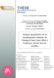
Figure 6: ASTEC calculations of the collapsed water level in the steam generators The Incident on Paks NPP The ICARE2 code (Ref. [2]), which is planned to be used in the ASTEC code for modeling of the core degradation instead simplified DIVA module, was used to simulate the incident with cleaning tank at Unit-2 Paks NPP (Hungary) occurred on the 10th April 2003. A severe damage of fuel assemblies took place in this incident. The 30 assemblies were being cleaned in a special tank below the water level of the spent fuel storage pool in order to remove crud buildup. When the chemical cleaning was completed the assemblies were being cooled by circulation of storage pool water. Due to insufficient heat removal from the fuel rods inside the cleaning tank a dryout and heating-up of fuel assemblies took place. A brittle failure of all fuel assemblies occurred during assemblies reflooding after cleaning tank cover lock opening. The following modeling approach was used for cladding thermal mechanical behaviour simulation. Both working and follower type assemblies with different burnup from 9 up to 27 MWd/kgU were considered. Axial decay heat distribution in the fuel rods was taken into account. The simulation of fuel behaviour described the cladding ballooning, flow blockage formation, cladding and shroud material oxidation. VVER-type of cladding material (Zr+1%Nb) oxidation kinetics was implemented into ICARE2 code.
The first European Review Meeting on Severe Accident Research (ERMSAR-2005) Aix-en-Provence, France, 14-16 November 2005
SESSION 7. Code application and PSA methodologies. Paper No 1
Use of the ICARE2 code allowed to predict the fuel assemblies temperature behaviour, fuel rod cladding ballooning and burst, cladding and shroud oxidation versus assembly type, burnup and assembly location in the cleaning tank. The claddings embrittlement zones (in which the ECR value exceeds the zero ductility limit) extend from the elevation 1.3 m up to 2.7 m in the first ring of the fuel assemblies and from 1.5 m up to 2.5 m in the third ring. These calculation results agree with observation of damaged fuel assemblies in the tank obtained with help of the video cameras. As an example the calculated and observed values of the cladding embrittlement zone extension for the fuel assembly #13 situated in the second ring are presented below (Fig. 7). Reconstruction of the assembly #13 appearance Embrittlement zone
Elevation, m
3
2
13
1
Zero ductility limit 0 0
10
20
30
ECR, %
40
Fuel assembly arrangement in the cleaning tank
Figure 7: ICARE2 calculation of cladding embrittlement zone for fuel assembly #13
D.
DISSEMINATION AND EXPLOITATION OF THE RESULTS
The present work on ASTEC code adaptation to VVER provides the opportunity to disseminate acquired European knowledge and experience on severe accident simulation among the Russian design organizations. At the same time it provides positive feedbacks on the European ASTEC code. After completion of the ASTEC code adaptation to VVER it can be used for: • • • •
Safety analysis of NPPs with VVER; Cross verification of Russian severe accident codes; Prolongation of the existing NPPs with VVER operation beyond the design limit; Development of severe accident management procedures for new design of the NPPs with VVER.
The first European Review Meeting on Severe Accident Research (ERMSAR-2005) Aix-en-Provence, France, 14-16 November 2005
SESSION 7. Code application and PSA methodologies. Paper No 1
E.
CONCLUSIONS
A first stage of the work in collaboration between NSI RRC KI and IRSN has been successfully achieved through the transfer of the ASTEC code to NSI RRC KI, the users’ training and first applications to VVER. A specific VVER validation matrix was developed: CORA and CODEX experiments on VVER bundle degradation; RASPLAV AW-200 experiments on corium interaction with reactor lower head; BETA V7.1 and ACE L4 experiments on MCCI; HD experiments on hydrogen distribution in a VVER-1000 containment mock-up; RUT experiments on hydrogen combustion in the hydrogen-air-steam mixtures. This validation task is in progress with the ASTEC V1 code, and will continue with the next versions of the codes. The first results of code validation show a satisfactory agreement between calculated and measured data in the tests specific to VVER. The applications of ASTEC code to hypothetical severe accident sequences on the VVER-1000 and to real incidents on NPPs with VVER-1000 and VVER-440 show the code acceptability and functionality for calculations, but also the need for some modelling improvements, especially for simulation of specific systems in a new generation VVER-1000: hydroaccumulators 2nd stage; passive heat removal system and some others. The next stages of the collaboration will consist to complete the modeling specifications of above VVER safety systems, and in parallel to work on validation and reactor applications of the modules under development of the next version of the ASTEC code. That would be fruitful to continue this work in collaboration with SARNET Network where similar work on ASTEC code will be done. REFERENCES [1] J.P. Van Dorsselaere, J.C. Micaelli, H.J. Allelein, “ASTEC and SARNET – Integrating Severe Accident Research in Europe”, International Congress on Advances in Nuclear Power Plants (ICAPP’05), Seoul, May 15-19, 2005 [2] G. Le Dantec, M. Zabiego, P. Chatelard et al., “ICARE2 V3mod1.3 and ICARE/CATHARE V1mod1.3: Release Guide”, Technical note IRSN/DRS/SEMAR 03/51, May (2003)
The first European Review Meeting on Severe Accident Research (ERMSAR-2005) Aix-en-Provence, France, 14-16 November 2005