Low voltage regulation, the match rating interrupt- ing capacity of the breaker and a restraint on the inrush current are equally emphasised. The objective is ...
Asymmetrical winding configuration to reduce inrush current with appropriate short-circuit current in transformer J.-F. Chen, T.-J. Liang, C.-K. Cheng, S.-D. Chen, R.-L. Lin and W.-H. Yang Abstract: A method for transformer design with an asymmetric winding configuration to reduce the inrush current with appropriate voltage regulation and short-circuit current is proposed. Differing from the traditional symmetric winding structure in transformer design, this method can provide the high inrush equivalent inductance and suitable leakage inductance for a transformer. The formulas of the leakage inductance and inrush equivalent inductance are derived for the asymmetric winding configuration. Theoretical analyses showing the desirable winding configuration that the inrush current can be reduced to with appropriate voltage regulation and short-circuit current are presented. Using the inferential result in experiments, the inrush current can be successfully limited under a low voltage regulation and a suitable short-circuit current.
1
Introduction
The magnetising transient inrush current is frequently encountered during the switching of a transformer. The inrush current has various effects on the protective devices of the transformer, generally reducing the quality of the power system. The mechanical structures of the transformer may be destroyed due to the increased magnetic forces caused by the inrush current [1]. The inrush current can be limited by additional control circuitry [2–4] and the interior improvement method [5, 6]. Controlled switching requires additional control circuitry. The effect of the remanent transformer flux on the switching-on point has been investigated [2, 3]. The method of controlling the switching-on angle never works in practice because of uncertainties such as the parameters of the spring and the remanent flux in the circuit breaker, and the phase of the source that provides power to the circuit-breaker coil, among others. The interior improvement method of airgap windings (AGW) is based on the use of a core with a DC source to introduce an airgap into the magnetic circuit during the switching-on period [5]. The method worsens some of the characteristics in the magnetic circuit and its reduction of the inrush current is finite. The inrush equivalent inductance can be increased by changing the distribution of the coil windings for reducing inrush current [6]. But, the high inrush equivalent inductance must be appropriately designed according to considerations of voltage regulation and the rating interrupting capacity of the circuit breaker. Several factors are considered in designing transformers, such as weight, output power, efficiency of power conversion, cost etc. [7–12]. Most steady-state characteristics of a
transformer have been improved using many theoretical analyses and experiments. Nevertheless, reducing the inrush current of a transformer has seldom been discussed. This paper describes a novel concept for transformer design. Low voltage regulation, the match rating interrupting capacity of the breaker and a restraint on the inrush current are equally emphasised. The objective is procured by appropriate asymmetric winding configurations. Differing from the traditional symmetric winding structure in transformer design, this method can provide the high inrush equivalent inductance and suitable leakage inductance for a transformer with changing the cross-sectional area of the primary winding. The inrush current can be reduced by the larger inrush equivalent inductance. So, if the crosssectional area of the primary winding is increased, then the inrush equivalent inductance will also be increased. The asymmetric winding configurations can obtain this effect. The inrush current can be effectively reduced with a twolayered structure, but high voltage regulation may also occur because of the high leakage inductance. In this paper, a transformer designs with the three-layered S-P-S and the four-layered S-P-S-P structures are discussed. It does not address other structures such as the P-S-P and P-S-P-S structures, since their constraints on the inrush current are not as favourable as that associated with the S-P-S-P structure. 2
Problem formulation
This work seeks to obtain a high inrush equivalent inductance while retaining a suitable leakage inductance that enables low voltage regulation and a small short-circuit current by modifying the design as little as possible. So, the leakage inductance must also be considered.
r IEE, 2005 IEE Proceedings online no. 20040985 doi:10.1049/ip-epa:20040985 Paper first received 2nd February and in revised form 20th July 2004 J.-F. Chen, T.-J. Liang, C.-K. Cheng and R.-L. Lin are with the Department of Electrical Engineering, National Cheng Kung University, Tainan, Taiwan S.-D. Chen is with the Department of Electrical Engineering, Chinese Naval Academy, Kaohsiung, Taiwan W.-H. Yang is with the Grand Power River Co., Ltd., Taiwan, Chia-Yi, Taiwan IEE Proc.-Electr. Power Appl., Vol. 152, No. 3, May 2005
2.1
Structure of S-P-S
The S-P-S structure is defined by the presence of one primary winding between the inner and outer secondary windings.
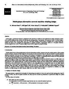
2.1.1 Leakage inductance: Figure 1 schematically depicts a shell-type transformer with the S-P-S structure. 605
From the relevant literature [7–12], the magnetomotive force between the top and bottom of the coils for different depths z, is given by curve 1 z zI2 N2 the m:m:f: at depth z ¼ I2 xN2 ¼ S1 S
secondary coil (1)
dz
2.1.2 Inrush equivalent inductance: Magnetis-
iron core
S1 = xS P S2 = (1−x)S d d4
d3
d2
NI
d1
depths
curve 1 m.m.f. curve
Fig. 1
Three-layer structure cutaway view
d thickness of interval between iron and coil d1, d2, d3, d4 thickness of insulation paper h height of core window li inner peripheral length of coil winding N1 number of turns in the primary winding N2 number of turns in the secondary winding P thickness of primary winding S total thickness of secondary winding S1 ¼ xS thickness of inner secondary winding S2 ¼ (1�x)S thickness of outer secondary winding m0 permeability of free space x distributive ratio of secondary winding
ing inrush is a transient and occurs primarily when a transformer is energised. During this period, the inrush equivalent inductance is one of the main causes of the reduction in the inrush current. Increasing this inrush equivalent impedance reduces the inrush current. Accordingly, the characteristics and magnitude of this inrush equivalent impedance must be understood. The impedance of the transformer is a combination of inductance and resistance. The magnitude of the winding resistance is so small that it can be ignored in the discussion of the restraining inrush current. Reference [6] provides the methods for computing the magnitude of the inrush equivalent inductance. Figure 2 shows the relationship between the m.m.f. curve of the inrush current and the structural dimensions. The total inrush equivalent inductance in the S-P-S structure is ð8Þ LinS�P �S ¼ LinðaÞ þ LinðbÞ where LinðaÞ
LinðbÞ
l þr1 �r1
li þ d1 þ xS þ d2 ; 2p r2 ¼r1 þ P ; a1 ¼ l2 þ r22 ; a2 ¼ l2 þ r12
ð3Þ
r1 ¼
The total magnitude of leakage inductance due to S1 is described in (4). � � x2 N22 m0 xS d2 ðli þ 8d1 Þ þ 2x2 S 2 þ F1 LS1 ðxÞ ¼ ð4Þ 3 h 2 where F1 ¼ li+8d1+8xS+4d2. Like (4), the each leakage inductance due to S2 and the primary winding P are defined in (5) and (6). � � ð1 � xÞ2 N22 m0 ð1 � xÞS d3 2 2 � 2ð1 � xÞ S þ F3 F2 LS2 ðxÞ ¼ 3 h 2 ð5Þ �� � �� xP d2 N12 m0 2 2 2 x F4 � 2x P þ F1 LP ðxÞ ¼ 3 2 h � �� ð1 � xÞP d3 2 2 2 þ 2ð1 � xÞ P þ F3 þ ð1 � xÞ F4 3 2 606
r2 r 2 l2 3=2 3=2 1=2 1=2 ðr2 a1 � r1 a2 Þ þ ðr2 a1 � r1 a2 Þ 2 4 1=2 r 2 þ a1 r 2 l4 r2 þ � ln þ ðr24 � r14 Þ 1=2 4 2 r 1 þ a2 # 5=2 5=2 ða1 � a2 � r25 þ r15 Þ l2 3=2 3=2 � ða1 � a2 Þ þ 5 3 " # � � 2 N12 m0 li 2 �d ¼ p r1 � l2 ffi pffiffiffiffiffiffiffiffi 2p 2 2 �
If the permeability of coil m ¼ m0, in the region of S1, the flux linkage ls10 can be obtained as z zI2 N2 m0 � ðli þ 8d1 þ 8zÞdz dl0S1 ¼ xN2 � xS S h � � ð2Þ 2 2 x N2 I2 m0 xS ðli þ 8d1 Þ þ 2x2 S 2 l0S1 ¼ 3 h In the region of d2, the reluctance due to S1 is l