Tushar N. K. Jain, Paul V. Gratz, Alex Sprintson and Gwan Choi. Department ...... [12] D. Mangano, R. Locatelli, A. Scandurra, C. Pistritto, M. Coppola,. L. Fanucci ...
Asynchronous Bypass Channels: Improving Performance for Multi-Synchronous NoCs Tushar N. K. Jain, Paul V. Gratz, Alex Sprintson and Gwan Choi
Department of Electrical and Computer Engineering, Texas A&M University {tnj07,pgratz,spalex,gchoi}@tamu.edu Abstract—Networks-on-Chip (NoC) have emerged as a replacement for traditional shared-bus designs for on-chip communications. As with all current VLSI designs, however, reducing power consumption in NoCs is a critical challenge. One approach to reduce power is to dynamically scale the voltage and frequency of each network node or groups of nodes (DVFS). Another approach to reduce power consumption is to replace the balanced clock tree with a globally-asynchronous, locally-synchronous (GALS) clocking scheme. NoCs implemented with either of these schemes, however, tend to have high latencies as packets must be synchronized at intermediate nodes between source and destination. In this paper, we propose a novel router microarchitecture which offers superior performance versus typical synchronizing router designs. Our approach features Asynchronous Bypass Channels (ABCs) at intermediate nodes thus avoiding synchronization delay. We also propose a new network topology and routing algorithm that leverage the advantages of the bypass channel offered by our router design. Our experiments show that our design improves the performance of a conventional synchronizing design with similar resources by up to 26% at low loads and increases saturation throughput by up to 50%. Index Terms—NoC, GALS, asynchronous interconnect, on-chip networks.
I. I NTRODUCTION With the continued advance of Moore’s Law, ever increasing transistor densities are yielding ever greater numbers of processing elements (PEs) on chip, resulting in the current proliferation of chip-multiprocessor (CMP) and system-onchip (SoC) designs. As the number of PEs increases, the communication between those components is becoming ever more critical. Networks-on-Chip (NoCs) have recently emerged as a scalable alternative to the bus-based and ad-hoc interconnect seen in past designs. NoCs leverage the design techniques of multi-hop interconnection networks developed for the large scale multiprocessor computers of the 1990s, to provide lowlatency, scalable communication between PEs on chip. Although Moore’s law continues to provide greater transistor densities, current generation VLSI presents several challenges going forward. In particular, balancing performance against the energy and power consumption in a given design is a challenge. A popular method to achieve this balance is dynamic voltage and frequency scaling (DVFS) [1]. In CMP and SoC designs which support DVFS, the voltage and frequency of individual PE nodes, or sets of PE nodes are dynamically managed to reduce overall power and energy consumption while maintaining enough performance to meet application demands [2]. Another common approach to reduce the power and energy consumption in CMPs and SoCs is the use of a globally-asynchronous, locally synchronous (GALS) clocking
66
65
64
63
62
61
60
56
55
54
53
52
51
50
+
46
45
44
43
42
41
40
36
35
34
33
32
31
30
34
+ +
+
+
24
33
+
25
24
23
22
21
20
16
15
14
13
12
11
10
06
05
04
03
02
01
00
23
+
26
+
RED
BLUE
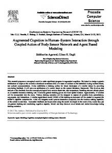
Fig. 1: An ABC network topology showing red and blue chains. Also depicts path traversed between (0,6) and (6,4). scheme [3]. In traditional VLSI design, a single synchronized clock is maintained throughout the entire chip. These synchronized architectures require fully balanced clock distribution trees to ensure minimal clock skew between communicating components. Fully balanced clock distribution trees, however, consume a significant portion of the total chip power which can be as high as 30% of the total power consumed by the chip [3]. On-chip power consumption can be reduced by replacing the balanced clock tree with a GALS clocking scheme which only guarantees minimal clock skew within the local processing element. PEs in both DVFS and GALS systems can be implemented as multi-synchronous systems with each PE operating in their respective clock domains which may have different phase and frequency relations. Communication between such nodes typically requires synchronization into the receiver’s clock domain in order to avoid metastability problems caused by violations of setup or hold time of the flip-flops when latching data from a different clock domain [4]. A well established approach to avoiding metastability involves adding multiple stages of latching on incoming signals to reduce the likelihood of a metastable event. While this approach allows reliable communication across clock domains, it comes at the cost of an added two or three cycles of latency for every clock domain traversal. As the number of CMP and SoC PE nodes increases, the number of clock domains which data must traverse between source and destination will increase, thereby increasing the effective latency of that communication. This latency has
been shown to directly impact the system performance and the overall cost [5]. With low communication latency as our objective, we propose a new router microarchitecture for multi-synchronous NoCs which avoids synchronization delay at the intermediate nodes via an asynchronous by-pass channel (ABC) around these nodes. We also propose a novel 2-D grid based topology and routing algorithm to complement our router design. The main contributions of this paper are: 1) We present the ABC router design, a novel router design which offers a highly skew tolerant solution to DVFS and GALS NoCs; 2) ABC routers offer a low latency, asynchronous bypass path through the intermediate routers, avoiding synchronization delay and latching at intermediate nodes; 3) We also present an optimized network topology and routing algorithm to leverage the advantages of ABC routers. II. M OTIVATION The intuition behind the ABC design is that a packet should not be required to latch at the intermediate nodes within an NoC. At a minimum, intermediate node latching results in one cycle of overhead for synchronous designs and at least two cycles of overhead for multi-synchronous designs which require synchronization. If intermediate node latching can be avoided, a significant fraction of the packet latency overhead can be removed. In the absence of network congestion, a packet should not, in-fact, require latching at intermediate nodes. While at high congestion, when multiple packets are vying for the same buffer FIFO and output port resources, the packet must be latched at the intermediate nodes as it waits for the contention to clear. At low congestion levels, however there is no such constraint. As we will show, the ABC design offers an asynchronous bypass path which bypasses the buffer FIFOs as well as synchronization at the intermediate nodes. Thus the packets can virtually fly through the network without getting latched at the intermediate nodes, reaching there destination with a delay approaching the wire delay of the connecting links. III. N ETWORK O PERATION On its path through the network a packet traverses three node classes, the source node, intermediate nodes and the destination node. In a typical GALS or DVFS NoC each of these nodes may operate in its own clock domain. The goal of the ABC router design is to reduce or remove latching and synchronization at the intermediate nodes. Furthermore, the routers should independently and dynamically determine the availability of the bypass channels without the overheads of allocation or setup and tear-down. In this section we discuss the design and operation of the ABC router to show how these goals were met. A. ABC Network Architecture As illustrated in the packet propagation path shown Figure 1, we observe that packets traversing a given intermediate node router are most likely to travel straight, that is from input port on one side of the router to output port on the opposite
Fig. 2: ABC router microarchitecture design. side. In a typical 2D Mesh network, a minimum length path between any two nodes may be found which has at most one turn. We propose to leverage this observation by biasing our ABC routers towards the straight path over the turn path. ABC routers are pre-disposed to allow the asynchronous propagation of packets along the straight path, as long as conditions allow. In 2D Mesh networks, only a limited set of sourcedestination pairs require no turn during packet traversal, those pairs which are in the same column or row. We observe that it should be possible to gain a further benefit from the ABC router’s straight path bias if the network topology provides a greater number source-destination pairs which do not require a turn. To this end, we propose a new class of network topologies, the double-chain topology, one of which is shown in Figure 1. A double-chain topology is comprised of two disjoint but overlapping chains, each of which connects all network nodes. Double-chain topologies provide an advantage over 2D Mesh networks for ABC routers by providing two paths comprised solely of “straight-path” links between all source-destination pairs. As the traditional 2D mesh terminology of North, South, East and West is less useful in a double-chain topology, we will label these chains the red chain and a blue chain respectively. As shown in Figure 1, nodes within each chain are perceived to be ordered such that traversing a given chain in one direction is considered to be increasing (e.g. the red+ direction) and traversing that chain in the opposite direction is considered to be decreasing (e.g. the red- direction). Jumping from one chain to other is referred to as a turn. To avoid deadlock in the network, the chains themselves are ordered, and a jump is allowed only from the blue chain to the red chain and not the vice-versa. B. Router Microarchitecture Figure 2 shows a high-level block diagram of the proposed ABC router. Similar to a typical 2D Mesh NoC router, the
ABC router contains five input and output ports corresponding to the four neighboring directions and the local processing element (PE). All communications are carried out in the form of packets, subdivided into flits, which are sent through the NoC using wormhole flow-control. The ABC router design is source-synchronous, hence each port’s link is comprised of a clock bit along with data bits and an on/off flow control bit. Both the data and clock signals travel same link length and router logic, therefore they face nearly the same delay and their skew does not increase much for each hop traversed. Nevertheless, after place and route, if an unexpected skew is observed between the clock signal and the flits, transparent latches or buffers may be inserted to reduce it, at the cost of some added latency. 1) Packet Structure: ABC packets are deterministically source routed, i.e. they have a full set of routing directions encoded into the header. Source routing is used to ensure a minimal delay and skew induced at each hop. The three most significant bits of each flit contain flit type (Header, Body or Tail) and a valid bit. The fourth and fifth most significant bits of the header flit encode the routing directions for the packet at that particular node. After each hop, the current routing bits are shifted away until only a flag is left which marks arrival at the destination. Since the static shift operation can be achieved without any logic, we are able to retrieve the next hop information at the node without impacting the skew between the flits and its clock signal. 2) Router Datapath: As shown in Figure 2, the ABC router contains five output unit blocks corresponding to each direction. These output unit blocks are broken into three types. Output block “A” connects the blue (+ or -) and local inputs to the opposite blue chain output, while output block “B” connects the all the possible inputs to the corresponding red output. Block “C” connects all possible inputs to the router’s local PE. Block “A” has a smaller set of inputs because it is illegal to route from a red input to a blue output as discussed in Section III-A. At the intermediate nodes, if a packet travels straight through the router, it is desirable that the packet be forwarded without latching. To this end, output blocks “A” and “B” both contain an “ABC Path” which the router is pre-disposed to use in the absence of congestion. When an incoming flit arrives, it is simultaneously latched into the synchronous FIFO (syncFIFO) and propagated along the ABC path towards the output mux. In the absence of congestion, indicated by a lack of packets currently waiting for the output port and the presence of favorable downstream control flow, the flit is propagated through the output port mux via the ABC and the contents of the sync-FIFO are flushed away. Alternately, if the buffer FIFOs are not empty, indicating presence of older packets, the contents of the sync-FIFO are forwarded to the straight path bi-synchronous FIFOs [6] (bi-FIFOs) and the output port is fed by one of the bi-FIFOs. Thus, the sync-FIFO acts as a backup in case the flit was not able to successfully utilize ABC. Alternately, if the packet needs to turn at that particular node, the flits are latched into one of the turn path bi-FIFOs. Although there are no buffer FIFOs along the ABC path, we
employ bi-synchronous FIFOs (bi-FIFOs)[6] to store packets in the event of congestion. Bi-FIFOs allow writes and reads to be done in different clock domains, although they require an overhead of two to three clock cycles to avoid metastability. In the ABC routers, bi-FIFO writes are done in the incoming clock domain and reads are done in the local clock domain. Overall the complete router has 10 bi-FIFOs, two of which are shared between block “C” and the two block “B”s. The path joining a given input port with the same color output port (e.g. red- to red+), is referred to as a “straightpath”. All other paths are referred to as turn paths as shown in Figure 2. Each turn path is made up of a single bi-FIFO. The sync-FIFOs are standard FIFOs which are clocked in the incoming clock domain. In the current ABC router design, the ABC is only a bypass around the straight path FIFOs, as shown in Fig. 2. We considered providing ABC paths for the turns as well, but the approach was not followed, due to exponential increase in FIFOs required to implement it. ABC routers employ on/off flow control. This signal which is generated at the downstream node, needs to be synchronized with respect to the outgoing clock of the upstream node. Thus, summing up the round trip latency, which is nearly 1.5 times the clock cycle as discussed in Section IV and two cycles for synchronization, to ensure no flit gets dropped in the process, the depth of the FIFO must be overcommitted by at least four more than the maximum packet length. 3) Router Arbiter: As shown in Fig. 2, the output channel is shared between ABC, the straight path bi-FIFO and turn path bi-FIFOs. To avoid livelock and ensure routing fairness the arbiter selects the ABC path in the ABC mode, and arbitrates among the bi-FIFOs according to the Round Robin algorithm. However, on transition from ABC mode to FIFO mode, the straight path bi-FIFO is given a priority. As shown in Fig. 2, the router arbiter is divided into two types of control modules for each output unit block, the clock control module (Ccontrol) and the data control module (Dcontrol). The Ccontrol module arbitrates the output clock while the Dcontrol module controls the output data. As the Ccontrol and Dcontrol modules receive inputs from two different clock domains, metastability must be addressed. We avoid all metastable conditions through control logic synchronization as explained in the next section. Further detail on metastability avoidance is given in Section III-B4. On arrival of a head flit at the output, the router becomes active and remains in this state until a tail flit arrives, when it becomes idle. Arbitration occurs in the idle state, except if an off signal is received from the downstream node while the ABC is in use in which case the chosen path is switched to the straight path bi-FIFO. 4) Control Logic: The control logic in an ABC router can be represented as a Moore finite state machine (FSM). The various states of this FSM are displayed in Figure 3. Each output port in the ABC router operates in one of two modes: ABC mode where flits are forwarded along with the upstream or the incoming clock, and FIFO mode where incoming packets are synchronized into the local clock domain and forwarded along with the local clock. This ensures that the
▪There are no packets in BI-FIFOs AND ▪Downstream node does not transmits an OFF ▪There are no packets in BI-FIFOs AND ▪Downstream node does not transmits an OFF
▪There are no packets in BI-FIFOs AND ▪Downstream node does not transmits an OFF
ABC
State 9
State 8
▪Output Clk: Incoming Clk ▪Output Clk: Incoming Clk ▪ Data Path: ABC Output Clk: Incoming Clk ▪ Data Path: ABC ▪Sync-FIFO FLUSH: Enabled ▪ Bi FIFOs READ: Disabled ▪Output Clk: Incoming Clk ▪Output Clk: Incoming Clk ▪ Data Path: ABC ▪ Data Path: ABC Output Clk: Incoming Clk ▪Sync-FIFO FLUSH: Enabled
ABC
State 9
ABC
State 1
State 1
State 8
▪ Bi FIFOs READ: Disabled ▪Output Clk: Deactivated ▪Data Path: ABC ▪Sync-FIFO FLUSH: Disabled
State 9
▪Output Clk: Incoming Clk ▪ Data Path: ABC ▪Sync-FIFO FLUSH: Enabled *A packet arrives at any ▪ Bi FIFOs READ: Disabled
StateState 8 7
▪Output Clk: Incoming Clk ▪ Data Path: ABC
Output Clk: Incoming Clk Output Clk: Incoming Clk
of the Inputs OR State 7 * A local packet is generated OR ▪Output Clk: Deactivated * Downstream node transmits an OFF ▪Data Path: ABC Output Clk: Incoming Clk ▪Sync-FIFO FLUSH: Disabled * A packet arrives at any of the Inputs OR * A local packet is generated OR ▪Output Clk: Deactivated * Atransmits packet arrives at any of the Inputs OR * Downstream node an OFF ▪Data Path: ABC Output Clk: Incoming Clk OR at any of the Inputs OR ▪Sync-FIFO FLUSH: Disabled * A local packet*isAgenerated packet arrives * Downstream node transmits an OFF * A local packet is generated OR Output Clk: Deactivated ▪Output Clk: Deactivated arrives at any of the Inputs OR * Downstream node transmits an OFF State 6 State 2 ▪ Data Path: Bi-FIFO ** AA packet local packet is generated OR ▪Bi-FIFOs READ: Disabled * Downstream node transmits an OFF
State 1
State 7
State 6
State 2
Output Clk: Deactivated
▪Output Clk: Deactivated ▪ Data Path: Bi-FIFO ▪Bi-FIFOs READ: Disabled
* A packet arrives at any of the Inputs OR * A local packet is generated OR * Downstream node transmits an OFF
State 2
State 3
FIFO
State 4
State 5
State 6
▪Output Clk: Deactivated ▪ Data Path: Bi-FIFO ▪Output▪Bi-FIFOs Clk: LocalREAD: Clk Disabled ▪Output Clk: Local Clk ▪Output Clk: Local Clk ▪ Data Path: Selected Bi-FITO Output Clk: Deactivated ▪ Data Path: Bi-FIFO ▪ Data Path: Straight path ▪Sync-FIFO FLUSH: Enabled ABC ▪Bi FIFOs READ: Disabled Bi FIFO ▪Output Clk: Local Clk ▪ Bi FIFOs READ: Enabled ▪Output Clk: Local Clk ▪Output Clk: Local Clk ▪ Data Path: Selected Bi-FITO Output Clk: Deactivated ▪ Data Path: Bi-FIFO ▪ Data Path: Straight path ▪Sync-FIFO FLUSH: Enabled ABC ▪Bi FIFOs READ: Disabled Bi FIFO ▪ Bi FIFOs READ: Enabled
State 3
FIFO
State 4
FIFO
▪Output Clk: Local Clk ▪ Data Path: Selected Bi-FITO ▪A packet in any of the BI-FIFOs ORFLUSH: Enabled ▪Sync-FIFO ▪Downstream transmits an▪ BiOFF FIFOs READ: Enabled
Output Clk: Deactivated
State 5
State 3
State 4
State 5
▪Output Clk: Local Clk ▪ Data Path: Bi-FIFO ▪Bi FIFOs READ: Disabled
▪Output Clk: Local Clk ▪ Data Path: Straight path ABC Bi FIFO
Output Clk: Deactivated
▪A packet in any of the BI-FIFOs OR ▪Downstream transmits an OFF
Fig. 3: FSM depicting the working of the router. ▪A packet in any of the BI-FIFOs OR
transmitsthus an OFF output data flits are synchronous with the▪Downstream output clock avoiding potential metastability conditions downstream. The ABC state and the FIFO state are two stable states for this FSM. The state machine can stay in any other state for only one cycle of the local clock. The trigger signal for transition from one mode to another is generated in the outgoing clock domain. This signal is then synchronized into the desired clock domain by standard, two-cycle synchronization. Once the trigger signal has been synchronized the transition to the new clock begins and only after a successful transition of the clock is the datapath switched, thus avoiding potential metastability conditions in the control logic. ABC Mode to FIFO Mode: Transition from ABC mode to FIFO mode for a given output port occurs on the arrival of a packet in one of the bi-FIFOs or an off signal from the downstream node. As presented in the Fig. 3, in both the cases, first the output clock is switched to the local clock (State 1). The datapath is then switched to one of the bi-FIFOs depending on which has a packet in it (State 2). The straight path bi-FIFO is given preference just after the transition to ensure that all the flits of a packet on ABC pass through the router before a new packet is transmitted thus avoiding interleaving. In State FIFO the router begins transmission of the packets present in the bi-FIFO. During the normal operation in FIFO mode, the bi-FIFOs are selected by Round Robin algorithm. The flits are then transmitted depending on the off signal from the downstream node. Altogether the transition from ABC mode to FIFO model takes three cycles to complete. This added latency is not seen
by flits traversing the straight path because they are already latched into the sync-FIFO. FIFO Mode to ABC Mode: This transition occurs when the FIFO mode is currently selected and there are no flits occupying any FIFO associated with the port. These transitions can be divided into 4 stages corresponding to States 3 to States 9 in Figure 3: (i) In the first stage, the read signals of all the bi-FIFOs are deactivated. This makes sure that no packet is read out during the clock transition (State 3). (ii) If all the turn buffer FIFOs are empty, the straight path is then selected as the output datapath, (State 4). (iii) In the third stage if the straight path bi-FIFO is empty and the downstream node is not transmitting an off signal, the output clock is switched to the incoming clock;(State 5 to State 8). It takes at least two cycles for the arrival of a packet at the input of the bi-FIFOs to translate in the reading clock domain, so to ensure that no packet was latched into the bi-FIFO while the clock transition was taking place, this stage takes four cycles to complete. (iv) In the final stage, the datapath is switched to ABC State 9. However, if a flit arrives on the straight-path in any of the above mentioned stages the transition is aborted and the datapath is switched back to the straight path bi-FIFO at a cost of three additional cycles. IV. T OPOLOGY AND ROUTING A LGORITHM As discussed in Section III-A, we propose a new class of topologies, double-chain topologies, to leverage the advantages of our ABC router design. In particular, double-chain topologies take advantage of the lower latency of the straightpath over the turn-path in an ABC router. These topologies are comprised of two disjoint but overlapping chains, each of
(a) Serpentine
(c) Sickle
(b) Hook
(d) ’H’ Shape
Fig. 4: 2-D topologies for ABC router network. which connects all network nodes. As the possible space of all possible double-chain topologies is large, in this section we discuss the selection of a double-chain topology and routing algorithm suitable for the 2D planar silicon substrate of current NoCs. A. Topology Characteristics To limit the state space of to those networks that might be easily implemented in 2D planar silicon, we began with the following restrictions: • The topology should not require more router ports than a typical 2D Mesh would require (five ports in total). Adhering to this restriction helps ensure that the design complexity and area of the ABC router remains similar to that of a 2D Mesh router. • Each topology must consist of only two chains, each of which must pass through every network node. Simple analysis shows that it is not possible to connect all nodes with more than two chains without increasing the number of router ports or subdividing the network into nonoverlapping chains. Subdividing the network into more than two non-overlapping chains always performs worse than connecting the non-overlapping chains together. • Each chain may only connect near neighbor nodes together in one hop. This restriction ensures that there are no “fly-over” links, links which pass through but do not connect to a given node. Fly-over links reduce the maximal wire density without adding to a node’s I/O bandwidth. • The overall maximum bisection bandwidth of the topology must not be significantly more than that of a standard mesh topology. Strictly speaking, connecting all network nodes together in two chains will always require at least one more bisection link than a comparable 2D Mesh topology. We will only examine topologies which increase bisection wire density minimally and in our evaluation we will ensure packet flit counts are adjusted to reflect the slightly reduced available wire density.
Note that for the purposes of this discussion we will examine chains rather than rings, to simplify deadlock avoidance. The intent of double-chain topologies is to increase the number of source-destination pairs which are connected by straight-paths, thereby reducing the average packet latency. In order to evaluate the relative merits of individual topologies we must understand the relative latencies of the straight-path versus the turn-path. B. Router Traversal Latency When not experiencing congestion, packets traversing an ABC router may take either a straight-path ABC channel or be latched into a turn-path bi-FIFO. The latency of bi-FIFO is two cycles. Thus, combined with the latency of the control logic, there is a penalty of three cycles for a packet to make a turn. Alternately, packets which traverse the router on a straightpath, utilizing the ABCs, will only face the link delays. According to the International Technology Road map for Semiconductors [7], assuming 22 nm technology, the global clock frequency would be around 3 GHz while the link delay should be between 700-1300 ps/mm. Thus, we will assume the link delay, combined with the small amount of combinatorial logic delay in each router to be approximately 75% of a clock cycle. C. Routing Algorithm To complement the new, double-chain topologies we use with ABC routers, we developed a modified version of standard XY dimension order routing (DOR). Our routing algorithm leverages the observation that in any double chain network there are always three different routes between any two nodes: 1) following the straight-path on the blue chain, 2) following the straight-path on the red chain, or 3) following a DOR path starting on the blue chain and turning to the red chain. Our algorithm attempts to optimize packet route based upon assumptions of link and turn delays under no load. Suppose that each link between two adjacent nodes causes a delay of x clock cycles. A turn costs 3 cycles in addition to the link delay. If a flit turns it faces an additional delay of (3/x + 1) times the link delay. Thus, if the number of hops is less than or equal to (3/x + 1), traveling on ABC is a better choice than making a turn. Traveling along the straight path requires more hops than this value, turning leads to less delay in terms of clock cycles. Our routing algorithm selects from among the three legal paths between a source-destination pair based upon this estimation of latency under no-load. Using the estimated router latencies discussed in Section IV-B, yields a turn cost of (3/.75 + 1) = 5. Thus, for the given topologies, we remain on the same chain if the number of hops is less than or equal to five else we make a turn. As can be seen from the Fig. 1, a packet generated at (0,6) will travel only through the blue chain to reach (6,4). D. Analysis In this subsection we discuss our selection of doublechain topologies for a 7x7 network. Initially we ran a brute force search to find the optimum topology. We exhaustively
25
CLOCK CYCLES
10
NUMBER
20
OF
AVERAGE CASE WORST CASE
15
5
0 SERPENTINE
HOOK
SICKLE
H SHAPE
TOPOLOGY
Fig. 5: Average and worst case hop count for the four topologies. computed all the possible topologies that met the topology restrictions described in Section IV-A and evaluated them based upon average, zero-load latency for random traffic given the routing algorithm described in Section IV-C. Using this technique we were able to find the optimum topologies for 4x4 and 5x5 network, however due to the exponential expansion of the solution set we were unable to compute the optimal topology for larger networks. Instead, we extrapolated the top four results obtained from the evaluation of 4x4 and 5x5 networks to up to a 7x7 by network and then compared the four resultant topologies to determine the best topology. Figure 4 depicts the four topologies evaluated for an 7x7 2-D network. The evaluation results for these topologies are shown in Figure 5. The figure shows both the average, as well as the worst case no-load, packet latency for every possible source-destination pair. As shown, the Serpentine topology performs the best with respect to both the average as well as the worst case latency. This is because it is the only topology among the four, in which each node is connected to all its physical neighbors through both the chains resulting in lower cost paths in comparison to the other topologies for all source and destination pairs. The Hook topology is also a close contender. We found, however, that as the turn-path penalty decreases with respect to the straight path, the Serpentine topology performs better than the Hook topology. Therefore, we use the Serpentine topology for our implementation. These four topologies do not represent all possible topologies, and we plan to investigate an optimal ABC topology further in future work. V. E XPERIMENTS AND E VALUATION In this section, we evaluate ABC routers experimentally to gain an understanding of their performance under different types of synthetic and realistic workloads. We compare ABC’s performance against a baseline, synchronizing router design. A. Methodology In these experiments, we evaluate a network of ABC routers connected in the 7x7 2-D Serpentine topology depicted
in Fig. 4(a) and implemented using the routing algorithm described in Section IV-C. To capture ABC router network performance results, a fully synthesizable, Verilog implementation of the ABC network was designed and simulated. The baseline design consists of an 7x7, 2-D mesh network with XY DOR routing. In the baseline design packets are synchronized at every hop, incurring a delay of three clock cycles per hop. The baseline router has two, eight-flit-deep, virtual channels (VCs) per port, yielding approximately the same area overhead as the ABC router. We evaluated three types of synthetic workloads: uniform random, bit complement, and transpose. In all cases packets were injected according to a uniform random process. Five experimental runs were completed for each workload and the mean and standard deviation of the results are shown. Packet length was varied randomly between two to five flits and the simulator was run for 1000 cycles of warm-up followed by 5000 monitored packets. To determine the performance under a realistic workload the ABC network was also evaluated under network traces taken from the SPLASH-2 suite of benchmarks [8]. The traces were obtained from a forty-nine node, shared memory CMP system simulator, arranged in a 7x7 2-D mesh topology [9]. Due to the simulator performance limitations associated with full Verilog simulation of all 49 cores, we were forced to run only a small portion of the actual trace. To have an un-biased evaluation, we chose 500,000 cycles from the middle of each trace with a warm-up period of 10,000 cycles. Finally, the Serpentine topology, shown in Fig. 4(a), has one extra bisectional link than a standard 2D Mesh topology. Assuming equal bitwidths between the ABC and baseline topologies would give the ABC network 14.28% more bisection bandwidth. To approximate a uniform wire density across all bisections between the ABC and baseline designs, we decreased the number of flits in each baseline network packet by one relative the ABC design. B. Synthetic Traffic Fig. 6 compares the latency performance of ABC router with the baseline for uniform random, transpose, and bitcomplement workloads. In uniform random traffic, each source is equally likely to send a packet to each destination. Among the three traffic patterns, random traffic uniformly balances load even for topologies and routing algorithms that normally have poor load balance. The other two patterns concentrate on individual source-destination pairs, thus stress the load balance of a topology and routing algorithm [10]. For uniform random traffic, shown in Figure 6(a), ABCs offer 20% improvement in no-load latency and saturation throughput is improved by 50% over the baseline design. The improvement in the saturation throughput occurs due to our topology’s increased number of bisectional links compared to a standard mesh network. Transpose traffic, in Figure 6(b), shows little improvement in the no-load latency. This is because, for transpose traffic, packets must always take a turn due to the arrangement of source-destination pairing. Saturation throughput, however, is
(a) uniform random
(b) transpose
(c) bit-complement
Fig. 6: Average latency vs injection rate
C. Realistic Traffic Figure. 7 presents the relative performance of the ABC network with respect to the baseline design for the SPLASH2 traces. From the figure it can be observed that ABC outperforms the baseline design in all the traces except one, (LU), where baseline is marginally better than ABC. ABC shows an improvement of nearly 30-35% over the baseline design for FFT and Water-Spatial. The Geometric Mean for the relative latency is 84.5% less than baseline thus, on the average, the ABC network performed 15.5% better than the baseline design for the fraction of realistic traffic observed. VI. R ELATED W ORK In this section we describe the connections between this work and other works which address performance improvements in asynchronous interconnection networks and new topologies to reduce hop count. A. Asynchronous Interconnect A critical aspect of multi-synchronous interconnect design is avoidance of metastable state due to a violation of setup or hold time of the flip-flops and registers present in the system. In the metastable state the output of the system is unpredictable. A well established approach for synchronization
1.2
1 0.8
RELATIVE LATENCY
greatly improved as compared to the baseline design. For bit complement traffic, shown in Figure 6(c), ABCs offer an improvement of 26% in no-load latency as well as 26% percent improvement in saturation throughput. In bit complement traffic, packets travel further than the other two synthetic patterns; therefore, ABC’s benefits compound resulting in much better performance than baseline. Generally, ABCs outperform baseline for all the workloads. An important feature common for all the three loads is the shape of the curve. In all the three graphs the shape of the curve for the ABC design is uneven, unlike the baseline. For example, for random traffic there is a distinct bump in latency at 15% traffic. At around 8% traffic, congestion causes the routers to switch back and forth between FIFO and ABC modes leading to an increase in the acceleration of latency until the load becomes large enough that the routers get locked in FIFO mode, thus causing a fall in the rate and thus a bump is formed.
0.6 BASELINE
0.4
ABC
0.2 0
SPLASH TRACES
Fig. 7: Relative Performance against baseline for realistic workload (SPLASH-2) in NoCs was proposed by Panades and Greiner, in the form of an optimized bi-synchronous FIFO featuring low-latency and small footprint [6]. This FIFO adds a latency of two and three clock cycles to gain robustness against metastability. Another solution, presented by Dally and Poulton, consists of delay-line synchronizers, using a variable delay on the data lines [11]. This delay avoids switching in the metastable window of the receiving registers. This solution requires careful, post-manufacturing tuning to ensure metastability is avoided. Variable delay lines also may make this solution undesirable as they are not always available in standard cell libraries. Mangano et. al. proposed the skew insensitive link (SKIL) solution to address metastability in mesochronous interfaces [12]. SKIL supports arbitrarily skewed clock signals by relying on a two stage buffer FIFO structure by writing and reading flits into and from the buffer FIFO in a ping-pong fashion. It should be noted that some of the above synchronization solutions could be used to augment our ABC approach, we plan to explore this in future work. In each of the above techniques, data must be synchronized at each intermediate node. Synchronization delay at every hop forms a major portion of the total latency and can be reduced by either
lowering the hop-count or reducing the per-hop delay. Another facet of GALS architecture is a completely clockless implementation where information exchange occurs using a handshake to explicitly indicate the validity and acceptance of data. This is in contrast to the multi-synchronous and synchronous design styles, which use a globally distributed clock signal to indicate moments of stability of the data. Some popular implementations are CHAIN [13], MANGO [14], ANoC [15], and QNoC [16]. While, these techniques offer high performance in terms of latency and reduced idle power, they involve asynchronous or non-standard cell modules in the router design, whereas, ABC routers can be implemented using standard cells. B. Low Hop Count Topologies New topologies to lower the hop count have also been explored. Dally proposed express cubes which help in lowering the per-hop latency rather than the hop count [17]. An express cube is a k-ary n-cube, augmented by one or more physical links or express channels that allow nonlocal messages to bypass the intermediate nodes. Kim et al. and Grot et al. proposed topologies with higher radix routers, leading to lower hop counts but resulting in more complex router designs [18, 19]. Express virtual channels (EVCs) have also been proposed to reduce per-hop delay. EVCs virtualize the physical links in an express-cube, limiting wasted physical link bandwidth [20]. EVC-based flow control allows virtual bypassing of the packet at the intermediate nodes thus reducing the per-hop delay. This method is efficient for multi-hop packets but does not fare well for communications between neighboring routers. In contrast to the prior work, the ABC router design targets both the per-hop latency and the hop count to reduce network latency. ABC routers, thus, perform well for both long-haul and short-haul packet communication. Also in contrast to EVCs and express cubes, ABCs are physical links present in the router offering an asynchronous bypass from the buffer FIFOs. Since ABCs are inherent to the router, they can be dynamically assigned at every hop, unlike EVCs which must be allocated upstream at specific nodes only. A packet takes an ABC whenever possible thereby avoiding FIFOs and synchronization delay, resulting in a lower per-hop latency. VII. C ONCLUSIONS AND F UTURE W ORK In this paper we present the design, implementation, and evaluation of asynchronous bypass channel (ABC) routers. ABC routers aim to achieve lower latencies by eschewing synchronization and latching at the intermediate nodes between source and destination with a network. We present a detailed microarchitecture for an ABC router. We also present a new class of network topologies and associated routing algorithm to complement the router design. This new class of topologies, double-chain topologies, leverages the ABC router’s bias towards the straight path over the turn path. Our experiments show that our ABC router, interconnected via a double-chain topology, produces significantly lower latencies compared to baseline. This paper introduces a framework for ABC router based networks. Our future work will focus on improving the per-
formance of the network through lower latency synchronizing techniques in the turn path. We also plan to further investigate optimal topologies for ABC enhanced routers. As mentioned in Section III-B, skew reducing latches might be required if the links are physically long. Further study needs to be done in this direction. The presented network offers the benefit of path diversity which could not be exploited by the static routing algorithm thus necessitates employing a dynamic algorithm. Also, dynamic congestion information may be used to inform the mode switch between the FIFO and ABC modes to reduce the thrashing we see in lightly congested network and improve performance. R EFERENCES [1] P. Macken, M. Degrauwe, M. V. Paemel, and H. Oguey, “A voltage reduction technique for digital systems,” in IEEE International SolidState Circuits Conference, pp. 238–239, February 1990. [2] W. Kim, M. Gupta, G. Wei, and D. Brooks, “System level analysis of fast, per-core DVFS using on-chip switching regulators,” in International symposium on high-performance computer architecture, 2008. [3] T. Meincke, A. Hemani, S. Kumar, P. Ellervee, J. Oberg, T. Olsson, P. Nilsson, D. Lindqvist, and H. Tenhunen, “Globally asynchronous locally synchronous architecture for large high-performance ASICs,” in The IEEE International Symposium on Circuits and Systems (ISCAS), vol. 2, pp. 512–515, 1999. [4] M. J. S. Smith, Application-Specific Integrated Circuits. Addison-Wesley Professional, first ed., 1997. [5] P. Gratz, C. Kim, R. Mcdonald, S. Keckler, and D. Burger, “Implementation and Evaluation of On-Chip Network Architectures,” in International Conference on Computer Design, pp. 477–484, 2006. [6] I. Panades and A. Greiner, “Bi-Synchronous FIFO for Synchronous Circuit Communication Well Suited for Network-on-Chip in GALS Architectures,” in The First International Symposium on Networks-onChip (NOCS), pp. 83–94, 2007. [7] A. Allan, D. Edenfeld, W. Joyner, A. Kahng, M. Rodgers, and Y. Zorian, “International Technology Roadmap for Semiconductors,” IEEE Comput, 2002. [8] S. C. Woo, M. Ohara, E. Torrie, J. P. Singh, and A. Gupta, “The SPLASH-2 programs: characterization and methodological considerations,” SIGARCH Compututer Architecture News, vol. 23, no. 2, pp. 24– 36, 1995. [9] A. Kumar, L.-S. Peh, P. Kundu, and N. K. Jha, “Express Virtual Channels: Towards the Ideal Interconnection Fabric,” in The 13th International Symposium on Computer Architecture (ISCA), pp. 150– 161, 2007. [10] W. Dally and B. Towles, Principles and practices of interconnection networks. Morgan Kaufmann, 2004. [11] W. Dally and J. Poulton, Digital systems engineering. Cambridge Univ Pr, 1998. [12] D. Mangano, R. Locatelli, A. Scandurra, C. Pistritto, M. Coppola, L. Fanucci, F. Vitullo, and D. Zandri, “Skew insensitive physical links for network on chip,” in The 1st International Conference on NanoNetworks and Workshops (NanoNet), pp. 1–5, 2006. [13] J. Bainbridge and S. Furber, “CHAIN: A delay-insensitive chip area interconnect,” IEEE MICRO, pp. 16–23, 2002. [14] T. Bjerregaard and J. Sparso, “A router architecture for connectionoriented service guarantees in the MANGO clockless network-on-chip,” in Proceedings of the conference on Design, Automation and Test in Europe-Volume 2, pp. 1226–1231, IEEE Computer Society Washington, DC, USA, 2005. [15] P. Vivet, D. Lattard, F. Clermidy, E. Beigne, C. Bernard, Y. Durand, J. Durupt, and D. Varreau, “FAUST, an Asynchronous Network-onChip based Architecture for Telecom Applications,” Proc. 2007 Design, Automation and Test in Europe (DATE07), 2007. [16] D. Rostislav, V. Vishnyakov, E. Friedman, and R. Ginosar, “An asynchronous router for multiple service levels networks on chip,” in Proceedings of the 11th IEEE International Symposium on Asynchronous Circuits and Systems, pp. 44–53, IEEE Computer Society, 2005. [17] W. Dally, “Express cubes: Improving the performance of k-ary n-cube interconnection networks,” IEEE Transactions on Computers, vol. 40, no. 9, pp. 1016–1023, 1991. [18] J. Kim, W. Dally, B. Towles, and A. Gupta, “Microarchitecture of a highradix router,” ACM SIGARCH Computer Architecture News, vol. 33, no. 2, pp. 420–431, 2005. [19] B. Grot, J. Hestness, S. Keckler, and O. Mutlu, “Express Cube Topologies for on-Chip Interconnects,” in The 15th International Symposium on High Performance Computer Architecture (HPCA), pp. 163–174, Feb. 2009. [20] A. Kumar, L. Peh, P. Kundu, and N. Jha, “Express virtual channels: towards the ideal interconnection fabric,” in The 34th annual International Symposium on Computer Architecture (ISCA), pp. 150–161, 2007.