Siemens Catalog MC Part 2 · 2002/2003 ... SIEMENS servomotors have ..... All
induction motors 1PH7, 1PH4 and 1PL6: the following limits apply for all vibration
...
Catalog MC Part 2 • 2002/2003
Seite 1
Motion Control • Servomotors
Catalog MC Part 2 • 2002/2003
u1_u4_rue_mc-2002.fh10 Fri May 03 08:28:58 2002
motion control
SERVOMOTORS
Siemens Energy & Automation, Inc. Automation and Drives Motion Control Systems 5300 Triangle Parkway Norcross, GA 30092
High Performance Motors and Accessories
siemens world wide: www.siemens.com Siemens Energy & Automation: www.sea.siemens.com
Order No.: DRSP-02062
u2.fm Seite 1 Freitag, 3. Mai 2002 7:15 07
Catalogs of the Motion Control Series General Motion Control Catalog Part 1 SIMOVERT MASTERDRIVES MC 0.75 HP to 270 HP
Order No.: DRSP-02060 Catalog MC Part 2 High Performance Motors and Accessories
Order No.: DRSP-02062 General Motion Control Catalog Part 3 SIMODRIVE 611 universal and POSMO A Single-Motor and Multi-Motor Drives 1.5 HP to 160 HP
Order No.: DRSP-02080
0_1-2.fm Seite 1 Freitag, 3. Mai 2002 7:40 07
s Servomotors High Performance Motors and Accessories Catalog MC Part 2 · 2002/2003
Overview
1
Synchronous Servomotors
2
Asynchronous Servomotors
3
Built-on Accessories
4
Connecting Systems
5
Documentation
6
Configuration Aids
7
Dimension Drawings
8
Appendix
A
Supersedes: Catalog GMC Part 2 · 1999
The products and systems described in this catalog are sold under application of a management system certified by DQS. The DQS Certificate is recognized in all IQ Net countries. Management System
DQS-certified in accordance with DIN EN ISO 9001 Reg.-No. 1258-05 DIN EN ISO 14001 Reg.-No. 81342-01
0_1-2.fm Seite 2 Freitag, 3. Mai 2002 7:40 07
Note The technical data are intended for general information. Please observe the Operating Instructions and the references indicated on the products for installation, operation and maintenance. Trademarks ® COMBIMASTER, DURIGINIT, MICROMASTER, MOTION-CONNECT, SIMADYN, SIMATIC, SIMATIC HMI, SIMODRIVE, SIMOREG, SIMOTION and SIMOVERT are Siemens registered trademarks. All other products and system names in this catalog are (registered) trademarks of their respective owners and must be treated accordingly.
• The technical data, selection and ordering data (Order Nos.), accessories and availability are subject to alteration. • All dimensions in this catalog are stated in inches and in (mm). © Siemens E&A 2002
1_1.fm Seite 1 Freitag, 3. Mai 2002 7:41 07
Servomotors Overview 1/2
Brief description
1/3
Flow chart Selection procedure
1/8
Overview of types and rated data
1/11
Technical explanations
Siemens Catalog MC Part 2 · 2002/2003
1
1/1
1_2.fm Seite 2 Freitag, 3. Mai 2002 7:42 07
Servomotors
Overview
Synchronous Servomotors
Brief description SIEMENS servomotors have been specially designed to satisfy the high requirements placed on variable-speed drives.
Versions • Synchronous servomotors
1
• Asynchronous servomotors
Principal characteristics • Compact design • High power density and overload capability • High maximum speeds • Integral encoder system • High dynamic response due to low rotor moment of inertia • Excellent concentricity properties • Rugged, almost maintenance-free design.
Synchronous servomotors The special synchronous servomotors characteristics include:
1FK6 and 1FK7 servomotors The 1FK6 servomotors satisfy the requirements in the lower power range from 0.7 HP to 7 HP (0.5 kW to 5.2 kW). Their optimized design means they are the most economical solution for many applications. The new 1FK7 servomotors are based on the experiences gained with the 1FK6 range, and are especially characterized by: • an extremely high dynamic response (1FK7 HD, high dynamic), • compact design (1FK7 CT, compact) and • expanded range of performances and options. 1FT6 servomotors – high performance The 1FT6 servomotors can be used for extreme requirements in a power range from 25 HP to 61 HP (0.2 kW to 45 kW).
• high overload capability,
These motors are available with self-cooling in protection classes IP 64 to IP 68, with separate cooling, or with water cooling. The wide range of options means they are the optimum solution for many highend applications. 1FS6 servomotors – explosionprotected The 1FS6 servomotors are designed for use in Zone 1 hazardous areas. These motors conform to type of protection EEx de IIC T3.
1PH7, 1PL6, 1PH4 asynchronous servomotors The compact asynchronous motors supplement the synchronous servomotors for applications in the upper power range (up to 630 kW). Versions: • Force-cooled 1PH7 motors in protection class IP 55 • Water-cooled 1PH4 motors in protection class IP 65 • Air-through and force-cooled 1PL6 motors in protection class IP 23.
Asynchronous Servomotors These motors permit the full rated torque throughout the entire constant flux range. Depending on the requirements, the motors may be fitted with the appropriate options: • Encoders (incremental encoder HTL, resolver, sin/cos incremental encoder 1 Vpp , absolute-value encoder) • Holding brakes. Gearboxes can be mounted on all servomotors as required. The motors and Siemens Drives are optimally matched to one another to provide powerful drive systems.
Synchronous AC linear motors – 1FN3 The 1FN3 linear motors are especially characterized by • outstanding dynamic response • very high traversing velocity • excellent precision non-wearing drive components due to contactless drive power transmission.
• high dynamic response and • high static torque.
•
1/2
Siemens Catalog MC Part 2 · 2002/2003
1_2.fm Seite 3 Freitag, 3. Mai 2002 7:42 07
Servomotors
Overview
Asynchronous Servomotors
Synchronous Servomotors
Brief description
1
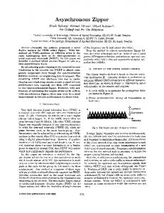
Optimal integration of drives into the world of automation PC/PG
SIMATIC HMI®
SIMATIC® S7
SIMOTION®
A DA65-5440c
PROFIBUS-DP
MICROMASTER
MICROMASTER® COMBIMASTER®
Standard AC drives
SIMOREG®
DC drives
SIMOVERT® MASTERDRIVES VC
AC drives with Vector Control
SIMOVERT MASTERDRIVES MC
Servo drives with Motion Control
SIMODRIVE®
Servo drives
SIMODRIVE POSMO A
Siemens Catalog MC Part 2 · 2002/2003
1/3
1_2.fm Seite 4 Freitag, 3. Mai 2002 7:42 07
Servomotors
Overview
Flowchart Selecting procedure
Synchronous Servomotors
Asynchronous Servomotors Speed [rpm] n
Basic information
In order to select the correct drive and motor, the specific speed and load cycle of the drive application must be known.
1
Step 1
Step 2
Step 3
Specifying the degree of protection: IP 23; IP 55; IP 64; IP 65; IP 67; IP 68
t i-1
ti
t
t
1) For 1FN3 applications torque is replaced by force.
For details, see Part 1
Specifying the type of construction: For details, see Part 7 IM B 3 (foot-mounting); IM B 5 (flange-mounting); IM B 35 (foot/flange-mounting)
Specifying the maximum torque from the load-cycle profile:
Step 5
Specifying the average (rms) torque:
Specifying the motor type needed (synchronous/asynchronous servomotor): 1FK6; 1FK7; 1FT6; 1FS6; 1PH7; 1PL6; 1PH4; 1FN3 See Overview in Part 1
Step 7
1/4
T
Specifying the supply voltage: 380 to 400 V; 460 to 480 V
Step 4
Step 6
t1 rated GMC-5152
Torque 1)
Siemens Catalog MC Part 2 · 2002/2003
1_2.fm Seite 5 Freitag, 3. Mai 2002 7:42 07
Servomotors
Overview
Asynchronous Servomotors
Step 7
Step 8
Step 9
Step 10
Flowchart Selecting procedure
Synchronous Servomotors
Selecting the motor from the corresponding data page (Part 2 or 3) which satisfies the following criteria: Synchronous servomotor: Asynchronous servomotor: nmax ≤ 1.1 × nn nmax must not be exceeded τeff ≤ τn τeff ≤ τn The load points (n, P) must be at least 30% below the stalling limit curve.
Specifying the encoder system needed: Incremental encoder HTL, resolver; sin/cos incremental encoder 1 Vpp; absolute-value encoder
1
For details, see Part 4
Complete motor order number with all the necessary options: 1FK6; 1FK7; 1FT6; 1FS6; 1PH7; 1PL6; 1FH4; 1FN3 For details, see Part 2 or 3 Order No. for motor: 1FK6 ¨¨¨-¨¨¨¨¨-¨¨¨¨ 1FK7 ¨¨¨-¨¨¨¨¨-¨¨¨¨ 1FT6 ¨¨¨-¨¨¨¨¨-¨¨¨¨ 1FS6 ¨¨¨-¨¨¨¨¨-¨¨¨¨ 1PH7 ¨¨¨-¨¨¨¨¨-¨¨¨¨ 1PL6 ¨¨¨-¨¨¨¨¨-¨¨¨¨ 1PH4 ¨¨¨-¨¨¨¨¨-Option + plain text 1FN3 ¨¨¨-¨¨¨¨¨-¨¨¨¨
Specifying the length and cross-section of the prefabricated power: cable needed or specifying the plug size for customer fitting: For details and order number structure, see Part 5
For details, see Part 5
Order number for power cable: Step 11 Specifying the prefabricated encoder cable needed or specifying the plug size for customer fitting: Incremental encoder HTL; resolver; sin/cos incremental encoder 1 Vpp; absolute-value encoder
In the case of standard overload 1)
Step 12
In the case of high overload conditions 2)
Step 13
For details, see Part 5
Order number for power cable:
Selecting the converter/inverter for the selected motor in the selection and ordering data on the basis of the standard overload conditions: The selection of converters/inverters in this catalog is based on the respective motor stall current or rated motor current. For 1FK6, 1FT6, 1FS6, see Part 2. For 1PH7, 1PL6 and 1PH4, see Part 3. Order number for drive: Bestimmung von Länge und Querschnitt der konfektionierten Leistungsleitung oder Bestimmung der erforderlichen Kupplung für Kundenmontage: If higher overload times and overload components are necessary, see catalogs MC Part 1 (SIMOVERT MASTERDRIVES MC), Part 3 (SIMODRIVE 611 universal and POSMO) or use the software tool SIMOSIZE. Bestellnummer Leistungsleitung:
1) 160% for 30 s or 136% for 60 s during 300 s load cycle.
siehe Teil 3
2) In the case of exceeding the standard overload.
Siemens Catalog MC Part 2 · 2002/2003
1/5
1_2.fm Seite 6 Freitag, 3. Mai 2002 7:42 07
Servomotors
Overview
Overview of types and rated data
1
Synchronous Servomotors
Asynchronous Servomotors
Motor/Types
Designation/Method of functioning
Degree of protection
Cooling
Size
1FK6
Servomotor Frameless permanentmagnet synchronous motor
IP 64 (IP 65 optional)
Natural cooling
36 to 100
1FK7 CT
Compact-servomotor (like 1FK6, but shorter)
Natural cooling
28 to 100
High Dynamic-servomotor with extremely low rotor moment of inertia
Natural cooling
36 to 80
(Compact)
1FK7 HD (High Dynamic)
1FT6
Servomotor-High Performance Permanent-magnet synchronous motor
Natural cooling IP 64 (IP 65, IP 67, IP 68 optional) Separate cooling Water cooling
28 to 132 80 to 132 63 to 100
1FS6
Natural cooling IP 64 Servomotor – explosion-proof Permanent-magnet synchronous (IP 65 optional) motor and EEx de II C T3 explosion protection
71 to 132
1FN3
Synchronous AC linear motor
IP 65
Water cooling
50 to 900
1PH7
Asynchronous servomotor Frameless three-phase squirrel-cage motor
IP 55
Separate cooling Surface cooling
100 to 280 1)
1PL6
Asynchronous servomotor Frameless three-phase squirrel-cage motor
IP 23
Separate cooling Axial ventilation
180 to 280 1)
1PH4
Asynchronous servomotor Liquid-cooled three-phase squirrel-cage motor
IP 65
Water cooling
100 to 160
1) Size 280 available as of third quarter 2002.
1/6
Siemens Catalog MC Part 2 · 2002/2003
1_2.fm Seite 7 Freitag, 3. Mai 2002 7:42 07
Servomotors
Overview
Asynchronous Servomotors
Synchronous Servomotors
Power range
Overview of types and rated data
Rated torque
Selection and ordering data on pages
0.7 HP 0.5 kW
7 HP 5.2 kW
7 to 148 Ibf-in 0.8 to 16.5 Nm
2/3 to 2/4
0.5 HP 0.4 kW
7.2 HP 5.4 kW
4.4 to 181 Ibf-in 0.5 to 20.5 Nm
2/6
8 to 106 Ibf-in 0.9 to 12 Nm
2/7
2.7 to 779 Ibf-in 0.3 to 88 Nm
2/9 to 2/14
61 HP 45.5 kW
150 to 1416 Ibf-in 17 to 160 Nm
2/10 to 2/14
4.3 HP 3.2 kW
37 HP 34 kW
89 to 690 Ib f-in 10 to 116 Nm
2/13
1.6 HP 1.2 kW
16.6 HP 12.4 kW
16.8 to 602 Ibf-in 1.9 to 68 Nm
2/17
45 to 1821 Ibf 200 to 8100 Nm
2/20
16 to 1829 Ibf-ft 22 to 2480 Nm
3/4 to 3/12
273 to 2655 Ibf-ft 370 to 3600 Nm
3/16 to 3/20
35 to 243 Ib f-ft 45 to 333 Nm
3/22
0.8 HP 0.6 kW
4.2 HP 3.1 kW
0.25 HP 0.2 kW
20.7 HP 15.5 kW
9.2 HP 6.9 kW
10.6 HP 7.9 kW
281 HP 214 kW
5 HP 3.7 kW
27.5 HP 20.5 kW
10 HP 7.5 kW
516 HP 385 kW
844 HP 630 kW
81 HP 65 kW
1
Siemens Catalog MC Part 2 · 2002/2003
1/7
1_2.fm Seite 8 Freitag, 3. Mai 2002 7:42 07
Servomotors
Overview
Synchronous Servomotors
Technical explanations
Asynchronous Servomotors
■ Specifications, standards, regulations
1
The motors comply with pertinent standards and specifications; please refer to the table.
Title
DIN/VDE
EN
IEC
General regulations for electrical rotating machines
DIN VDE 0530 Part 1
EN 60 034-1
IEC 60 034-1
As a result of the adaptation of national specifications to international recommendation IEC 60 034-1, already implemented in many countries, there are no longer any differences in coolant temperatures, temperature classes and temperature rise limits.
Terminal designations and direction of rotation for electrical machines
DIN VDE 0530 Part 8
EN 60 034-8
IEC 60 034-8
Types of electrical rotating machines
DIN VDE 0530 Part 7
EN 60 034-7
IEC 60 034-7
Cooling methods for electrical rotating machines
DIN VDE 0530 Part 6
EN 60 034-6
IEC 60 034-6
Degrees of protection for electrical rotating machines
DIN VDE 0530 Part 5
EN 60 034-5
IEC 60 034-5
Vibration severity of electrical rotating machines
DIN VDE 0530 Part 14
EN 60 034-14
IEC 60 034-14
Noise limits of electrical rotating machines
DIN VDE 0530 Part 9
EN 60 034-9
IEC 60 034-9
Cylindrical shaft ends for electrical machines
DIN 748 Part 3
–
IEC 60 072
The motors listed below are UL-approved to Underwriters Laboratories Inc.®, including the Canadian specification with the identification URc: 1FK6, 1FK7, 1FT self-cooled, 1PH72) (without brake) 1PL62) and 1PH4.
■ The most common degrees of protection of three-phase motors to IEC 60034-5 Depending on operating and environmental conditions, the choice of a suitable degree of protection is intended to prevent: • continuous effect of water, dust and foreign matter • contact with rotating parts within a motor • contact with live parts. The degrees of protection of electrical machines are indicated by a code consisting of two letters, two digits and, if applicable, an additional letter.
IP (International Protection) Identification letter for degrees of protection against contact and the ingress of foreign matter and water 0 to 6 First identification digit for degrees of protection against contact and the ingress of foreign matter 0 to 8 Second identification digit for degrees of protection against the ingress of water (no oil protection) W, S and M
The motors are supplied mainly in the following degrees of protection: Motor
Degree of protection
1st digit Contact protection
Opencircuit cooling
IP 23
Protection Protection against against contact medium-size solid with fingers foreign bodies of more than 12 mm dia.
Protection against rain water at up to 60 degrees from the vertical
Fancooled
IP 54
Full protection Protection against against contact harmful dust deposits
Splash water from all directions
IP 55 IP 64
2) Approbation for size 280 is pending.
1/8
Siemens Catalog MC Part 2 · 2002/2003
2nd digit Water protection
Water jets from all directions
Full protection Protection against Splash water from against contact the ingress of dust all directions
IP 65 1)
Water jets from all directions
IP 67 1)
Motor immersed in water under stated conditions of pressure and time
IP 68 1)
Motor is suitable for full immersion in water under conditions to be described by the manufacturer
Additional identification letter for special degrees of protection
1) According to DIN VDE 0530 Part 5 or EN 60 034 Part 5, there are only five degrees of protection for the first digit, and eight degrees of protection for the second digit for electrical rotating machines. However, IP 6 is contained in DIN 40 050 which generally applies to electrical apparatus.
Foreign matter protection
1_2.fm Seite 9 Freitag, 3. Mai 2002 7:42 07
Servomotors
Overview
Asynchronous Servomotors
Synchronous Servomotors
Technical explanations
■ Radial eccentricity tolerance, shaft and flange accuracy (concentricity and axial eccentricity to IEC 60 072 Radial eccentricity tolerance of the shaft with respect to housing axis (referred to the cylindrical shaft ends)
Concentricity and axial eccentricity of the flange surface with respect to the shaft axis (referred to the centering diameter of the mounting flange)
Frame size
Standard N in (mm)
Option R in (mm)
Frame size
Standard N in (mm)
Option R in (mm)
28
0.0014 (0.035)
0.0007 (0.018)
28
0.0032 (0.08)
0.0016 (0.04)
36
0.0014 (0.035)
0.0007 (0.018)
36
0.0032 (0.08)
0.0016 (0.04)
48
0.0016 (0.04)
0.0008 (0.021)
48
0.0032 (0.08)
0.0016 (0.04)
63
0.0016 (0.04)
0.0008 (0.021)
63
0.0039 (0.1)
0.002 (0.05)
71
0.0016 (0.04)
0.0008 (0.021)
71
0.0039 (0.1)
0.002 (0.05)
80
0.002 (0.05)
0.001 (0.025)
80
0.0039 (0.1)
0.002 (0.05)
100
0.002 (0.05)
0.001 (0.025)
100
0.0039 (0.1)
0.002 (0.05)
132
0.002 (0.05)
0.001 (0.025)
132
0.0049 (0.125)
0.0025 (0.063)
motor shaft
1
Test: concentricity
dial gauge motor dial gauge motor shaft motor shaft
A DA65-5773b
dial gauge
motor
Test: radial eccentricity
motor Test: axial eccentricity
A DA65-5774b
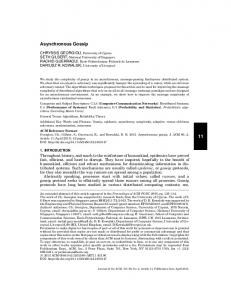
■ Vibration severity grades to IEC 60 034-14 electrical measuring instruments to DIN 45 666.
can lead to an increase in these values.
The specified values relate to the motor only. Installationrelated system vibrations
Speeds of 1800 rpm and 3600 rpm and the corresponding limit values are
Permissible vibration rate Veff [mm/s] stage N 3,5
4 stage R 3,2
3,0
3
stage S 3,0
2
1,8
0,89
0,71
0,71
0,45 0,28
0,45
2000
0,56
4000
2
1
0,75
6000
8000
10000
1,87
1,8
stage S
1,87 stage SR
1,4
1,12 ADA65-5834b
1
2,5 2,25
1,5 1,18
stage R
3,0
2,25 stage SR 1,85
1,8
1,4 1,12
4,0
3 2,4
1,87
Permissible vibration rate Veff [mm/s]
3,2
2,8
2,25
specified according to IEC 60 034-14. The speeds of 4500 rpm and 6000 rpm and the specified values have been stipulated by the motor manufacturer.
12000
14000
Limits of vibration severity grades for frame sizes 28 to 132.
16000 n [rpm]
1,12
1,12
0,71 0,45
0,71
1000
2000
3000
1,18 0,89 ADA65-5835b
The vibration severity is the rms value of the vibration rate (frequency range from 10 to 1000 Hz). The vibration severity is measured with
4000
5000
6000
7000
8000 n [rpm]
Limits of vibration severity grades for frame sizes 160 to 280.
Siemens Catalog MC Part 2 · 2002/2003
1/9
1_2.fm Seite 10 Freitag, 3. Mai 2002 7:42 07
Servomotors
Overview
Synchronous Servomotors
Technical explanations
Asynchronous Servomotors
■ Balancing to DIN ISO 8821 Requirements of the balancing process for fitted parts, particularly belt pulleys
1
The vibration response of motors fitted with belt pulleys is decisively governed by the balance of the fitted part, in addition to the balance quality of the motor. If the motor and the part to be fitted are balanced
separately before assembly, the balancing process for the belt pulley must be adapted to the balancing method for the motor. A distinction must be made between the following balancing methods for motors 1PH4, 1PH7 and 1PL6:
For 1PH7 and 1PL6 motors, the balancing method is coded in the ordering designation. Motors with half-keyed and full-keyed balancing are identified by the abbreviation “H” (half-key) and “F” (full-key) at the shaft end face.
•Half-keyed balancing •Full-keyed balancing •Smooth shaft end
Motors 1FK6, 1FK7 and 1FT6 with a fitted key are always half-key balanced.
The basic recommendation is for the highest demands for system balance quality. For motors with full-keyed balancing, belt pulleys with two opposite keyways are recommended, but only one key in the shaft end.
■ Vibration stress, induced vibration values Permanent-magnet synchronous motors 1FK6, 1FK7, 1FT6 and 1FS6: the following, maximum permissible limits for vibration stress at full reliability performance, apply only to motors without brake or with closed brake.
All induction motors 1PH7, 1PH4 and 1PL6: the following limits apply for all vibration values induced in the motor from the exterior: Vibration frequency
Vibration values for
Sizes 100 to 160
180 to 280
63 Hz
vibration acceleration a
≤ 2.55 m/s2
≤ 4.0 m/s 2
Vibration acceleration: • 10 m/s2 axial (20 Hz to 2 kHz) • 30 m/s2 radial (20 Hz to 2 kHz)
■ Coolant temperatue and installation altitude The rated power (rated torque) applies to continuous duty (S1 operation) to DIN EN 60 034-1 at rated frequency, at a coolant temperature of 104 °F (40 °C) and at an installation altitude of up to 3280 ft (1000 m) above sea level.
The motors are all designed to temperature class F and are utilized according to temperature class F. In the event of different conditions, the permissible power (torque) must be determined according to the table. Coolant temperature and installation altitude are rounded off to 41 °F (5 °C) and 1640 ft (500 m). Remark concerning the surface temperature: The temperature of the motor surface can reach 212 °F (100 °C) and more.
Water-cooled motors The recommendation for the coolant inlet temperature is 77° F (25 °C). In order to prevent moisture condensation, the cooling-medium inlet temperature can, depending on the ambient temperature, be up to 140 °F (60 °C).
1/10
Non- and blower-ventilated motors Installation altitude above sea level in ft (m)
Coolant (air) temperature in °F (°C) 95% Instead of V belts, the power output can also be transmitted from the gear drive output shaft by a spur gear pinion (available on request) or coaxially by means of a flexible coupling.
Installation, mode of operation The 2-speed gear units have a planetary design. The central sun gear distributes the power to several planetary wheels which revolve around it. The outstanding advantage of this design is its compactness. The gear-changing device, a foothed sleeve that moves axially, is of form-fit design. Position 1: Gear ratio i1 = 4. Position 2: Gear ratio i2 = 1. The motor is flange-mounted onto the gear unit by means of a ring adapter. The AC motor must be suitably prepared for mounting. At shaft heights of 160 mm and above, the type IM B 35 V 15 motor has to be supported at the non-drive end to prevent distortion. Any cantilever forces imported into the gear unit have to be borne by the gear unit and transmitted to the machine base.
The motor for all 2K gear units must be full-key balanced with fitted key. Because the 2K 120, 2K 250 and 2K 300 gear units are enclosed, the motor flange is adequately sealed in the standard version. Vertical mounting positions for the IM V 15 and IM V 36 require circulating oil lubrication of the gear units. The standard version of the gear units up to and including the 2K 300 has a maximum torsional play of 30 angular minutes (measured at the gear unit output). The play is almost identical whatever the ratio. Various different special versions are available on request: • Reduced play with special features: max. 20’ • Reduced play for high performance: max. 15’ The drive unit (i.e. the motor and gear unit) is supplied with vibration severity grade R according to EN 60 034-14 (IEC 60 034-14). This is also the case when the motor is ordered with grade S. The belt pulley 1) should be of the cup wheel type. For mounting the pulley, the output shaft on the gear unit has a flange with an external centering spigot and tapped holes. This ensures easy fitting and removal of the pulley.
1) Not included in scope of supply. Siemens Catalog MC Part 2 · 2002/2003
4/15
4
4_2.fm Seite 16 Freitag, 3. Mai 2002 7:51 07
Servomotors
Accessories
Asynchronous Servomotors
Built-on gears
■ 2-gear units (from ZF) Motor
Gear unit
Size
Type
Order No.
Permissible max. speed 2 )
Permissible rated torque (S1 duty)
Input nmax
Input
rpm
Moment of inertia Gear unit
Input
lbf -in (Nm)
Output i2 = 1 lbf -in (Nm)
i1 = 4 lbf -in (Nm)
lb f -in2 (Nm)
Output i2 = 1 lbf -in2 (Nm)
i1 = 4 lbf -in (Nm)
Output i2 = 1 lbf -in-s2 (kgm2)
Output i1 = 4 lb f -in-s2 (kgm2)
Gear unit weight Approx.
kg
100
2K 120
2LG4 312 - . . .
8000
1062 (120)
1062 (120)
4248 (480)
1239 (140)
1239 (140)
4956 (560)
0.097 (0.011)
0.1009 (0.0114)
30
132
2K 250
2LG4 315 - . . .
6300
2213 (250)
2213 (250)
8850 (1000)
3540 (400)
3540 (400)
14160 (1600)
0.239 (0.027)
0.5044 (0.057)
62
160
2K 300
2LG4 320 - . . .
6300
2655 (300)
2655 (300)
10620 (1200)
3540 (400)
3540 (400)
14160 (1600)
0.239 (0.027)
0.5044 (0.057)
70
180
2K 800 2K 801
2LG4 250 - . . . 2LG4 260- . . .
4000
7080 (800)
7080 (800)
28320 (3200)
7965 (900)
7965 (900)
31860 (3600)
1.731 (0.1956)
1.563 (0.1766)
110
225
2K 802
2LG4 270 - . . .
On requ.
For further technical data and planning instructions (such as on lubrication, temperature rise and typical applications), please refer to Catalog No. 4161 757 701d supplied by ZF (Zahnradfabrik Friedrichshafen). The ratings of the motor and gear unit are the governing factor in the design of the complete power unit (that is the AC motor and gear unit).
In the case of motor 1PH4168 or 1PH7167-2.B, for example, the rated torque must be reduced to 300 Nm. In the case of the motors of frame size 132, it should be noted that with normal lubrication the speed of the 2K 240 gear unit is restricted to 6300 rpm. The use of a gear unit permits the constant power band to be greatly increased.
Type for complete unit
Gear output shaft dimension D2 (see page 8/38)
2-speed gear unit (standard version) 1) Gear stage i1 = 4
in (mm)
Order No.
ZF designation
2LG4 312-3CC31
2K 120
For 1PH7 10. / 1PH4 10. motors IM B 5/B 35/V 1/ V 15
3.94 (100)
For 1PH7 13. / 1PH4 13. motors IM B 5/B 35
4.65 (118)
2LG4 315-3FD11
2K 250
IM V 1/V 15
4.65 (118)
2LG4 315-3FC11
2K 250
For 1PH7 16. / 1PH4 16. motors
P
with gear unit
IM B 35
5.12 (130)
2LG4 320-3JD11
2K 300
P =constant without gear unit
IM V 15
5.12 (130)
2LG4 320-3JC11
2K 300
P = constant
PN
For 1PH7 184 motors
1
2
IM B 35
7.09 (180)
2LG4 250-1JD11
2K 800
IM V 15
7.09 (180)
2LG4 250-1JC11
2K 800
For 1PH7 184 motors
A DA65-5943
4
Permissible maximum torque (S6-60% duty)
n N' = constant
n max
nN
n
1
= constant
2
Logarithmic scale
IM B 35
7.09 (180)
2LG4 260-1JD21
2K 801
IM V 15
7.09 (180)
2LG4 260-1JC21
2K 801
For further information about the gear units, please contact the manufacturer directly:
7310 Turfway Road, Suite 450 Florence, KY 41042 Phone: (859) 282-4300 Fax: (859) 282-4311 http://www.zf-group.com
Fig. 4/9 Speed/power graph Legend:
nN
Rated speed
nN’
Rated speed with 2-speed gear unit
nmax
Max. perm. speed
PN
Rated speed and constant power of the motor in the speed range from nN to nmax or nN’ to nmax
τ
Torque
1) Special versions such as gear units with different play, or other ratios (i = 3.17 or i = 5.5) are available on request.
4/16
Siemens Catalog MC Part 2 · 2002/2003
ZF Group North American Operations - Headquarters Florence, KY
ZF Maschinenantriebe GmbH
2) Higher drive speeds are allowed for gear ratios in some instances with oil-cooled gear units (see the ZF catalog).
D-88038 Friedrichshafen Phone: +49 (0) 75 41-77-0 Fax: +49 (0) 75 41-77-90 80 00 http://www.zf-group.de/zf-n
4_2.fm Seite 17 Freitag, 3. Mai 2002 7:51 07
Servomotors
Accessories
Asynchronous Servomotors
Synchronous Servomotors
Built-on gears
■ Planetary gears made by Bayside Motion The Bayside Motion Group offers planetary gearheads. The stealth helical planetary gears are well suited for use with the 1FK. and 1FT6 servomotors. For technical and selection information as well as mounting charts please contact Bayside directly at the following address:
Bayside Motion Group 27 Seaview Boulevard Port Washington, NY 11050 Phone: (516) 484-5353 Fax: (516) 484-5496 http://www.baysidemotion.com
Important notes If torque amplification elements are used such as gears, the increased mechanical stress must be borne by the gears and not by the motor.
The motor is dimensioned for mechanical stress in accordance with the maximum torque and the lateral-force diagram (chapter 7).
■ Planetary gears and spur-gear units from other gear manufacturers You can, of course, contact other gear manufacturers in order to find a useful combination of SIEMENS servomotors and gear units.
Planetary gears and spur-gear units from Heynau Antriebstechnik GmbH The 1FK., 1FT6, 1PH7 and 1PH4 motors can be combined with planetary gears of the EPR and FPR series to form compact, coaxial drive units. The EPR series with output shaft and the FPR series with output flange can be directly mounted onto the D-end of the motors. Spur-gear units of the GC series are also available for D-end mounting.
Technical characteristics:
Planetary gears Transmission ratio: single-stage i = 4 to 10, 2-stage i = 16 to 100 Max. permissible output torque: 45 to 3750 Nm Torsional play: single-stage < 3 arc min, 2-stage < 5 arc min Efficiency, single-stage: 98% Spur-gear units Transmission ratio: single-stage i = 3 to 7, 2-stage i = 8 to 30 Max. permissible output torque: 9 to 1500 Nm Torsional play: < 10 arc min Efficiency: 98% per stage
For planning and selecting gears in combination with SIEMENS servomotors, please contact:
Heynau Antriebstechnik GmbH Herr Gunter Bever Hofmark-Aich-Strasse 25 84030 Landshut Federal Republic of Germany Phone: +49-8 71 78 01-1 44 Fax: +49-8 7178 01-1 40
Harmonic Drive gear units HD Systems, Inc. 89 Cabot Court Hauppauge, New York, N.Y. 11788 USA Phone: (6 31) 2 31-66 30 Fax: (6 31) 2 31-68 03 http://www.HDSystemsInc.com Harmonic Drive Antriebstechnik GmbH Hoenbergstrasse 14 65555 Limburg Federal Republic of Germany Phone: +49 -64 3150 08-0 Fax: +49-64 3150 08 -18 Low-play planetary gear units Umbach Servogetriebe GmbH & Co. KG Herr Kübler Hinter dem Schloss 16c 74906 Bad Rappenau Federal Republic of Germany Phone: +49-72 64 91-35 51 Fax: +49-72 64 91-40 40
Siemens Catalog MC Part 2 · 2002/2003
4/17
4
4_2.fm Seite 18 Freitag, 3. Mai 2002 7:51 07
Servomotors
Accessories
Accessories for 1FN3 AC linear motors
Linear Motors
Precision cooler
Secondary section cover Primary section
Secondary section Power cooler
Terminal box
Cooler profile
Combination distributor
Fig. 4/10 Accessories for 1FN3 AC linear motors
4
■ Optional coolers
Slide plate
Primary section precision cooler
Cable connection
Primary section main cooler
Heat Flow
Air gap Secondary section cooler
Cooling profile
DA65-5984
Secondary section
Machine frame
Fig. 4/11 Optional coolers
In spite of water cooling, temperatures of up to 248 °F (120 °C) occur inside the primary sections due to the high force densities of the motor. In order to prevent these temperatures having a negative impact on the machine precision, 1FN3 motors can be thermally and completely encapsulated against the environment using the thermo
4/18
sandwich® principle using the optional secondary section cooler and precision cooler. The inner cooling circuit (main cooler) dissipates the largest proportion of the power loss PVN of the primary section and protects the primary section winding against overheating (refer to Section “Technical data”).
Siemens Catalog MC Part 2 · 2002/2003
The main cooler of the primary section must be operated with water cooling in order to be able to utilize the rated force FN of the motor, specified in the data sheets (without water cooling, and depending on the convection situation and machine construction, only approx. 50% of the rated force FN acc. to the data sheet).
Note For motors from frame size 600, secondary section cooling is mandatory to be able to use the rated force FN (acc. to the data sheet). This is because the power loss cannot be adequately dissipated without water cooling.
4_2.fm Seite 19 Freitag, 3. Mai 2002 7:51 07
Servomotors
Accessories
Accessories for 1FN3 AC linear motors
Linear Motors
■ Precision cooler (optional) Supplementary cooler to cool the primary section according to the thermo sandwich® concept. This is recommended for applications with high thermal requirements regarding the machine precision. The precision cooler on the upper motor section shields the environment against the high motor temperatures. Thermal insulators at the glands and the intermediate air chambers reduce the heat transfer from the primary section. The insulating function is provided by an air gap at the lower side of the primary section.
Fig. 4/12 Precision cooler
The lateral heat radiation sheets of the precision cooler also form air-filled intermediate spaces, which insulate the primary section sides from the machine itself. Thus, the primary section is encapsulated by a thermal insulation on all sides.
Linear motors Type
Optional components Precision cooler Order No.
1FN3 050-2W
1FN3 050-2PK00-0AA0
1FN3 100-2W
1FN3 100-2PK00-0AA0
1FN3 100-3W
1FN3 100-3PK00-0AA0
1FN3 100-4W
1FN3 100-4PK00-0AA0
The precision cooler dissipates the residual heat, which is transferred due to thermal radiation and conduction. This means, that the mounting surface temperature and the outer surface of the primary section can be kept constant in a tolerance bandwidth of between 0 and 3 K (referred to the intake temperature) under all operating conditions.
1FN3 100-5W
1FN3 100-5PK00-0AA0
1FN3 150-2W
1FN3 150-2PK00-0AA0
1FN3 150-3W
1FN3 150-3PK00-0AA0
1FN3 150-4W
1FN3 150-4PK00-0AA0
1FN3 150-5W
1FN3 150-5PK00-0AA0
1FN3 300-2W
1FN3 300-2PK00-0AA0
1FN3 300-3W
1FN3 300-3PK00-0AA0
1FN3 300-4W
1FN3 300-4PK00-0AA0
1FN3 450-2W
1FN3 450-2PK00-0AA0
1FN3 450-3W
1FN3 450-3PK00-0AA0
1FN3 450-4W
1FN3 450-4PK00-0AA0
1FN3 600-3W
1FN3 600-3PK00-0AA0
1FN3 600-4W
1FN3 600-4PK00-0AA0
1FN3 900-2W
1FN3 900-2PK00-0AA0
1FN3 900-4W
1FN3 900-4PK00-0AA0
4
Siemens Catalog MC Part 2 · 2002/2003
4/19
4_2.fm Seite 20 Freitag, 3. Mai 2002 7:51 07
Servomotors
Accessories
Accessories for 1FN3 AC linear motors
Linear Motors
■ Cooling profiles with plug or hose connection (optional) The total maximum heat transfer to the secondary section is less than 10% of the total power loss of the linear motor. The secondary section can be cooled and thermally insulated by using cooling profiles between the secondary section and machine according to the thermo sandwich® principle. Aluminum profile rails with continuous cooling ducts. They are placed under the secondary sections if high thermal requirements are placed on the machine accuracy. The cooling profiles are part of the secondary section cooling together with the secondary section end pieces.
The surface of the cooling profiles are thermally optimized. The contact surface to the secondary section absorbs the heat and transfers it to the cooling duct. On the other hand, the contact surface to the machine is low to minimize heat transfer to the machine itself. We recommend that thermal insulation and secondary section cooling is used under the following criteria: • Requirement for minimum heat transfer of the secondary sections to the machine (e.g. low distortion as a result of thermal effects).
• High power loss transfer to the secondary section (at high continuous feed force for short traversing paths and high continuous velocities). • 1FN3 motors from frame size 600 (necessary to use rated force Fn).
Warning During linear motor operation, the secondary section may not exceed the maximum temperature of 140 °F (60 °C), as otherwise the permanent magnets could be demagnetized.
Selection of cooling profiles Cooling profiles for secondary section cooling can be used with or without combinationdistributors. For use together with a combination-distributor, it is necessary to have the cooling profile selected with plug connections to make the connection to the combinationdistributor. If the cooling profile is used without combinationdistributor, then the end pieces of the profile must have hose sleeve nipples to accommodate a direct hose connection.
■ Cooling profiles with plug connection The table shows the available cooling profiles with plug connection to a combinationdistributor.
4
Linear motor Type
Combination-distributor Order No. 2)
1FN3 002-0TK04-1. .0
1FN3 100-0T.01-0AA0
1FN3 050-...
1FN3 050-0T.01-0AA0
1FN3 100-... 1FN3 150-...
1FN3 150-0T.01-0AA0
1FN3 300-...
1FN3 300-0T.01-0AA0 1FN3 003-0TK04-1. .0
1FN3 450-...
Length code When ordering a cooling profile you must match the length of it to the length of the secondary section. The length of the secondary section (permanent magnets) is determined by the motor size and the number of secondary sections used. That means when you select the cooling profile for your motor size you have to specify in the 14th and 15th digit of the part number the length of the cooling profile by indicating the numbers of secondary sections used. To indicate the length the following length code is used.
Cooling profile with plug connection Order No. 1)
1FN3 600-...
1FN3 004-0TK04-1. .0
1FN3 600-0T.01-0AA0
1FN3 900-...
1FN3 005-0TK04-1. .0
1FN3 900-0T.01-0AA0
For all motor sizes (050 to 900) Number of secondary sections
Only for motor sizes 050 to 150 Length code
Number of secondary sections
Length code
1
AB
17
BH
2
AC
18
BJ
3
AD
19
BK
4
AE
20
CA
5
AF
21
CB
6
AG
22
CC
7
AH
23
CD
8
AJ
24
CE
9
AK
10
BA
11
BB
12
BC
13
BD
14
BE
15
BF
16
BG
1) For the complete order number see length code below. 2) For the complete order number refer to the paragraph combination-distributor in this section.
4/20
1FN3 450-0T.01-0AA0
Siemens Catalog MC Part 2 · 2002/2003
The maximum length of a single cooling profile is 9.84 ft (3 m), which corresponds to 16 secondary segments for motor sizes 300 to 900 and up to 24 segments for sizes 050 to 150. For lengths above 9.84 ft (3 m) the cooling profile has to be split.
4_2.fm Seite 21 Freitag, 3. Mai 2002 7:51 07
Servomotors
Accessories
Accessories for 1FN3 AC linear motors
Linear Motors
■ Cooling profiles with plug connection Example 1 A 1FN3 600-3WB00-0AA1 is used with 4 secondary sections. The part number for the two cooling profiles with plug connection to a combination-distributor is therefore 1FN3 004-0TK04-1AE0.
The quantity necessary for this motor size is three of each cooling profile since they are placed underneath both sides and the middle of the secondary section (see Fig. 4/13).
Fig. 4/13 Cooling profile with connector plugs (unconnected) and combinationdistributor on each side. Total length >9.84 ft (3 m).
Example 2 A 1FN3 150-2WC00-0AA1 is used with 27 secondary sections. 27 sections exceed the length of 9.84 ft (3 m) or 24 segments for this motor size. Hence the cooling profile has to be split into 2 pieces with any length combination that adds up to the total of 27 secondary units. The part number for the two cooling profiles with
plug connection to a combination-distributor could be for instance 1FN3 0040TK04-1BD0 (13 unit lengths and 1FN3 002-0TK04-1BE0 (14 unit lengths). For this motor size the quantity two of the specified cooling profile part numbers is necessary since the profiles go under each side of the secondary section (see Fig. 4/14).
4 Fig. 4/14 Cooling profile with connector plugs (unconnected) and combinationdistributor on each side. Total length 9.84 ft (3 m).
Fig. 4/16 Cooling profile with connector plug and hose sleeve nipple for size 600 and 900. Total length >9.84 ft (3 m). Linear motor Type
Cooling profile with hose sleeve nipple on both ends
Cooling profile with hose sleeve nipple on Right (R)
Cooling profile with hose sleeve nipple on Left (L)
Order No. 1)
Order No. 2)
Order No. 2)
1FN3 002-0TK02-1. .0
1FN3 002-0TK06-1AC0
1FN3 002-0TK07-1AC0
1FN3 003-0TK02-1. .0
1FN3 003-0TK06-1AC0
1FN3 003-0TK07-1AC0
1FN3 600-.. .
1FN3 004-0TK02-1. .0
1FN3 004-0TK06-1AC0
1FN3 004-0TK06-1AC0
1FN3 900-.. .
1FN3 005-0TK02-1. .0
1FN3 005-0TK06-1AC0
1FN3 005-0TK06-1AC0
1FN3 050-.. . 1FN3 100-.. . 1FN3 150-.. . 1FN3 300-.. . 1FN3 450-.. .
Length code
1) For the complete order number see length code in “cooling profiles w/ plug connection” paragraph. 2) Cooling profiles with hose sleeve nipple have a fixed length of 2 secondary section lengths.
4/22
Siemens Catalog MC Part 2 · 2002/2003
4_2.fm Seite 23 Freitag, 3. Mai 2002 7:51 07
Servomotors
Accessories
Accessories for 1FN3 AC linear motors
Linear Motors
■ Secondary section end pieces (optional) Secondary section end pieces are available in four versions. Combination-distributor, combination-adapter and
cover end piece is only used to hold down the optional secondary section cover.
• Connects and branches the cooling-medium to the two cooling profiles at the beginning of the secondary section track. • Combines the coolingmedium flow and connects the cooling-medium discharge at the end of the secondary section track.
Fig. 4/17
DA65-5985
Combination-distributor For parallel water connection through the cooling profiles on all motor sizes (050 to 900). It has the following functions: • Retains the secondary section cover at the beginning and at the end of the secondary section track.
combination end piece are equipped with plug connections to connect to the cooling profiles. The
Fig. 4/18
Combination end piece The combination end piece is required to route the cooling-medium at the order end of the
4 DA65-5986
• Cooling-medium connection • Cooling-medium routing The pressure loss for this system is significantly higher than when cooling using the combination-distributors, and must therefore be carefully checked.
Fig. 4/19
secondary section track when serial water connection is used (only in combination with a combination-adapter).
DA65-5987
Combination-adapter Provides connection for the cooling-medium intake and discharge for serial water connection through the cooling profiles for motor sizes 050 to 450. It has the following functions: • Retains the secondary section cover
Fig. 4/20
Cover end piece For holding down the optional secondary section cover (only necessary if
secondary section cover and no combination-distributor or adapter is used).
Secondary section end pieces
Motor sizes
Part No.
Combination-distributor
050, 100, 150, 300, 450, 600, 900
1FN3. . .-0TJ01-0AA0
Combination-adapter
050, 100, 150, 300, 450
1FN3. . .-0TG01-0AA0
Combination end piece
050, 100, 150, 300, 450
1FN3. . .-0TF01-0AA0
Cover end piece
050, 100, 150, 300, 450, 600, 900
1FN3. . .-0TC01-0AA0
Motor size
Siemens Catalog MC Part 2 · 2002/2003
4/23
4_2.fm Seite 24 Freitag, 3. Mai 2002 7:51 07
Servomotors
Accessories
Accessories for 1FN3 AC linear motors
Linear Motors
■ Secondary section cover (optional) Continuous protection for the permanent magnets of the secondary section, manufactured from semimagnetic stainless steel plates. They attach themselves to the secondary
Secondary section cover
section magnets so that when worn they can be changed without any other tools.
section by indicating the numbers of secondary sections used in the 14th and 15th digit of the part number.
The cover is one continuous piece and matched to the length of the secondary
Motor sizes
Part No.
050, 100, 150, 300, 450, 600, 900
1FN3. . .-0TB00-1 . . 0
Motor size Number of secondary sections
0 AA 0 10 B B 1 20 C C 2 30 D D 3 40 E E 4 50 F F 5 60 G G 6 70 H H 7 80 J J 8 90 K K 9
4
The secondary section cover is also available as a segmented cover over 3, 4 or 5 secondary sections: Secondary section cover
Motor sizes
Part No.
050, 100, 150, 300, 450, 600, 900
1FN3. . .-4TP00-1A . 0
Motor size Number of secondary sections
D 3 E 4 F 5
Page 4/25 gives a complete overview of the available optional components for 1FN3 linear motors.
4/24
Siemens Catalog MC Part 2 · 2002/2003
4_2.fm Seite 25 Freitag, 3. Mai 2002 7:51 07
Servomotors
Accessories
Optional components for 1FN3 AC linear motors
Linear Motors
■ Ordering and planning data (overview) Linear motors
Optional components
Type
Precision cooler Order No.
Secondary section end pieces Order No.
Cooling profile 1) Order No.
Secondary side cover Order No.
1FN3 050-2W
1FN3 050-2PK00-0AA0
1FN3 050-0T@0@-0AA0
1FN3 002-0TK0@-1@ @0
1FN3 050-@ @ @00-1@ @ 0
1FN3 100-2W 1FN3 100-3W 1FN3 100-4W 1FN3 100-5W
1FN3 100-2PK00-0AA0 1FN3 100-3PK00-0AA0 1FN3 100-4PK00-0AA0 1FN3 100-5PK00-0AA0
1FN3 100-0T@0@-0AA0
1FN3 002-0TK0@-1@ @0
1FN3 100-@ @ @00-1@ @ 0
1FN3 150-2W 1FN3 150-3W 1FN3 150-4W 1FN3 150-5W
1FN3 150-2PK00-0AA0 1FN3 150-3PK00-0AA0 1FN3 150-4PK00-0AA0 1FN3 150-5PK00-0AA0
1FN3 150-0T@0@-0AA0
1FN3 002-0TK0@-1@ @0
1FN3 150-@ @ @00-1@ @ 0
1FN3 300-2W 1FN3 300-3W 1FN3 300-4W
1FN3 300-2PK00-0AA0 1FN3 300-3PK00-0AA0 1FN3 300-4PK00-0AA0
1FN3 300-0T@0@-0AA0
1FN3 003-0TK0@-1@ @0
1FN3 300-@ @ @00-1@ @ 0
1FN3 450-2W 1FN3 450-3W 1FN3 450-4W
1FN3 450-2PK00-0AA0 1FN3 450-3PK00-0AA0 1FN3 450-4PK00-0AA0
1FN3 450-0T@0@-0AA0
1FN3 003-0TK0@-1@ @0
1FN3 450-@ @ @00-1@ @ 0
1FN3 600-3W 1FN3 600-4W
1FN3 600-3PK00-0AA0 1FN3 600-4PK00-0AA0
1FN3 500-0T@0@-0AA0
1FN3 004-0TK0@-1@ @0
1FN3 600-@ @ @00-1@ @ 0
1FN3 900-2W 1FN3 900-4W
1FN3 900-2PK00-0AA0 1FN3 900-4PK00-0AA0
1FN3 900-0T@0@-0AA0
1FN3 004-0TK0@-1@ @0
1FN3 900-@ @ @00-1@ @ 0
Combination distributor (for parallel water connection of all cooler profiles and holding down the cover) Combination adapter (for one-sided water connection and holding down the cover; use only in combination with combination end piece) Combination end piece (for water redirection and holding down the cover; use only in combination with combination end piece) Cover end piece (holding down cover, without cooler profile Combination distributor, adapter, end piece for cooling profile with adapter nipple Combination distributor, adapter, end piece for cooling profile with plug-in coupling
J
G
4
F
C
0 1
Equipped with hose sleeve nipple for direct hose connection Pre-assembled with plug-in coupling for connection to combination distributors with plug-in coupling, adapters with plug-in coupling and end pieces with plug-in coupling Cooling profile for frame sizes: 1FN3050 to 1FN3450 with hose sleeve nipple, right 1FN3600 to 1FN3900 with hose sleeve nipples on both sides Cooling profile for frame sizes: 1FN3050 to 1FN3450 with hose sleeve nipple, left
Continuous secondary section cover several secondary sections Segmented secondary section cover 3, 4 or 5 secondary sections Examples: Number of secondary sections 1 14 16 24
Order No. for secondary section cover 1FN3 ..0-0TB00-1AB0 1FN3 ..0-0TB00-1BE0 1FN3 ..0-0TB00-1BG0 1FN3 ..0-0TB00-1CE0
1) Frame sizes 1FN3 050 to 1FN3 450: 2 pieces per secondary section track 1FN3 600 to 1FN3 900: 3 pieces per secondary section track
The maximum length of a single-section cooling profile that can be supplied is 9.84 ft (3 m). For the following frame sizes this corresponds to:
Number of secondary sections 0 10 20 30 40 50 60 70 80 90
2 4 6
7
0 TB 4 TP
0 1 2 3 4 5 6 7 8 9
A B C D E F G H J K A B C D E F G H J K
• 1FN3050 1FN3150 a maximum number of 24 secondary sections (AB to CE) • 1FN3300 to 1FN3900 a maximum number of 16 secondary sections (AB to BG).
Siemens Catalog MC Part 2 · 2002/2003
4/25
4_2.fm Seite 26 Freitag, 3. Mai 2002 7:51 07
Servomotors
Accessories Notes
Linear Motors
4
4/26
Siemens Catalog MC Part 2 · 2002/2003
5_1.fm Seite 1 Freitag, 3. Mai 2002 7:53 07
Servomotors Connecting Systems 5/2 5/3 5/4 5/6 5/7
Power cables MOTION-CONNECT® 500, 700 and 800 6FX5, 6FX8 and 6FX7, technical data 6FX5, 6FX8 and 6FX7, connection overview • for 1FK., 1FT6, 1FS6, 1PH., 1PL6 6FX7, for 1FN3 linear motors, sold by the meter • for 1PH7, 1PL6 and 1PH4 induction motors Flange for signal plug
5/12 5/14
Encoder cables • for connection to motors with an incremental encoder HTL • for connection to motors with a resolver 2-pole /multi-pole • for connection to motors with a sin/cos incremental encoder 1 Vpp • for connection to motors with an absolute-value encoder (EnDat) • for 1FN3 AC linear motors • for SIMODRIVE 611 universal
5/15
Cables • for SIMODRIVE POSMO CD/CA, SI
5/8 5/9 5/10 5/11
5
Siemens Catalog MC Part 2 · 2002/2003
5/1
5_2.fm Seite 2 Freitag, 3. Mai 2002 8:03 08
Servomotors
Connecting Systems Power cables MOTION-CONNECT 500, 700 and 800
Synchronous Servomotors
Asynchronous Servomotors
■ 6FX5, 6FX8 and 6FX7 power cables, technical data The new MOTION-CONNECT 6FX5 and 6FX8 cables replace the former standard (6FX4) as well as performance cables (6FX2) and add the new 6FX7 power cables with 4 temperature leads especially designed for 1FN3 linear motor applications. MOTION-CONNECT meets the DESINA color requirements, orange jacket for servo and frequency controlled drive power cables and green jacket for measurement cables like encoder cables.
The cost-effective 6FX5 standard cable is generally permanently routed while the performance 6FX8 cable can be universally used in fixed as well as in moving applications where the cable may be flered up to 10 million times (core cross section ≤ 6 mm2) during their life cycle. Furthermore the performance cable 6FX8 has compared to the standard cable higher operating temperature ratings, significant better acceleration
values and permissible traveling speeds, an increased oil resistance and is halogen / silicon-free. The 6FX5, 6FX8 and 6FX7 cables are sold by the meter but can also be supplied as prefabricated cables (with mounted connectors). The prefabricated cables with connectors offer the following advantages:
• They are subject to extensive tests, thus ensuring outstanding quality. • They are safe and reliable as they are optimally matched to the components which have to be connected. • The savings in logistics, construction and purchasing reduce overall costs.
• The exact length can be ordered to the meter.
The 6FX cables, prefabricated and sold by the meter, are described in detail on the following pages.
MOTION-CONNECT 500 6FX5 00. –.. .. type
MOTION-CONNECT 800 6FX8 00. –.. .. type
MOTION-CONNECT 700 6FX7 00. –.. .. type
Certifications Power/signal cables • VDE 1) • c/UL or UL/CSA • UL/CSA File No.2)
yes 758/C22.2N.210.2–M9C yes
yes 758/C22.2N.210.2–M9C yes
yes 758/C22.2N.210.2–M9C yes
Electrical data acc. to DIN VDE 0472 Rated voltage • power cable V0/V – supply cores – signal cores • signal cable
450/750 V 24 V (VDE) 1000 V (UL) 30 V
600/1000 V 24 V (VDE) 1000 V (UL/CSA) 30 V
600/1000 V 24 V (VDE) 1000 V (UL/CSA) –
Test voltage • power cable – supply cores – signal cores • signal cable
2 kVeff 1 kVeff 500 Veff
4 kVeff 2 kVeff 500 Veff
4 kVeff 2 kVeff –
Operating temperature on the surface • fixed cable • moving cable
–4 °F to 176 °F (–20 °C to +80 °C) 32 °F to 140 °F (0 °C to +60 °C)
–58 °F to 176 °F (–50 °C to +80 °C) –4 °F to 140 °F (–20 °C to +60 °C)
–58 °F to 176 °F (–50 °C to +80 °C) –4 °F to 140 °F (–20 °C to +60 °C)
Mechanical data Max. tensile stress Power/signal cables: • fixed cable • moving cable
7252 lbf /in2 (50 N/mm2) –
7252 lbf /in2 (50 N/mm2) 2900 lbf /in2 (20 N/mm2)
7252 lbf /in2 (50 N/mm2) 2900 lbf /in2 (20 N/mm2)
Smallest permissible bending radius • fixed cable (power cable) • fixed cable (signal cable) • moving cable (power cable) • moving cable (signal cable)
5 × Dmax 2.4 in (60 mm) – 7.1 in (180 mm)
6 × Dmax 2.4 in (60 mm) – 3.9 in (100 mm)
4 × Dmax – – –
Torsional stress
30 °/m absolute
30 °/m absolute
30 °/m absolute
Bends • 1.5 to 6 mm2 or signal • 10 to 185 mm2
100.000 100.000
10 Mio. 3 Mio.
10 Mio. 10 Mio.
Traverse rate • 1.5 to 6 mm2 or signal • 10 to 185 mm2
98 ft/min (30 m/min) 98 ft/min (30 m/min)
591 ft/min (180 m/min) 328 ft/min (100 m/min)
656 ft/min (200 m/min) 656 ft/min (200 m/min)
Acceleration
6.6 ft/s2 (2 m/s2)
16 ft/s2 (5 m/s2)
98 ft/s2 (30 m/s2)
Chemical data Insulation material
CFC-free, silicone-free
halogen-free, CFC-free, silicone-free, DIN 472 815/IEC 754-1
halogen-free, CFC-free, silicone-free, DIN 472 815/IEC 754-1
VDE 0472, part 803, type of test B (only hydraulic oil)
VDE 0472, part 803, type of test B
VDE 0472, part 803, type of test B
Outer sheath • power cable
PVC, color DESINA: orange RAL 2003
PUR DIN VDE 0282, part 10, color DESINA: orange RAL 2003
• signal cable
PVC, color DESINA: green RAL 6018
PUR DIN VDE 0282, part 10, color DESINA: orange RAL 2003 PUR DIN VDE 0282, part 10, color DESINA: green RAL 6018
Flame resistant
IEC 60 332.1
IEC 60 332.1
IEC 60 332.1
Technical data Cables
5
Oil resistance
The cables are not suitable for exposure to outdoor use. The technical data of these cables only apply to single bends with horizontal travel of up to five meters. Degree of protection for the customized power and signal cables and their extension cables when closed and plugged: IP 67 1) The corresponding registration numbers are printed on the cable sheath.
5/2
Siemens Catalog MC Part 2 · 2002/2003
2) The file no. of the respective manufacturers are printed on the cable sheath.
5_2.fm Seite 3 Freitag, 19. April 2002 8:49 08
Servomotors
Connecting Systems Asynchronous Servomotors
Power cables MOTION-CONNECT 500, 700 and 800
Synchronous Servomotors
■ 6FX5, 6FX8 and 6FX7, connection overview SIMOVERT MASTERDRIVES Motion Control
SIMOVERT MASTERDRIVES Vector Control
Incremental encoder TTL/HTL 6FX2 001–.....
6FX@ 002–2AH00–@@@01) ≤ 492 ft (150 m)
or X401 (SBP)
X414 (SBR)
6FX@ 002–2AH00–@@@0 ≤ 328 ft (100 m) (TTL) ≤ 492 ft (150 m) (HTL track A+B) ≤ 984 ft (300 m) (HTL track A*+B*)
6FX@ 002–2CF02–@@@0 ≤ 492 ft (150 m)
6FX@ 002–2CC71–1@@0 ≤ 328 ft (100 m)
X103 (CUVC)
external HTL encoder
or 6SX7 002–0AN00–@@@02) 6SX7 002–0AL00–@@@03)
or
≤ 492 ft (150 m)
Incremental encoder HTL 1PH7, 1PH4, 1PL6 motors
≤ 328 ft (100 m)
or 6FX@ 002–2AH00–@@@01)
X401 (SBP)
Absolute-value encoder 6FX2 001–5 .S.. with SSI
≤ 492 ft (150 m) (track A+B) ≤ 984 ft (300 m) (track A*+B*)
≤ 328 ft (100 m) or X424 (SBM2)
6FX@ 002–2CA31–1@@0 ≤ 328 ft (100 m)
or
sin/cos incremental encoder 1 Vpp 6FX2 001–3 .... 6FX2 001–3 ...
6FX@ 002–2EQ10–1@@0
5
1PH7, 1PH4, 1PL6, 1LA
Absolute-value encoder (EnDat) 6FX2 001–5.E..
sin/cos incremental encoder 1 Vpp 6FX2 001–3 .... in 1PH4, 1FK6, 1FK7, 1FT6, 1PH7, 1PL6 motors
Absolute-value encoder (EnDat) in 1PH4, 1FK6, 1FK7, 1FT6, 1PH7, 1PL6 motors
■ Current carrying capacity (Iz) of PVC-insulated copper
conductors acc. to IEC 60 204-1: 1997 ++ Corrigendum 1998 · Correction factors Crosssection
Current carrying capacity Iz with installation type C
Ambient air temperature
mm2
A
°C
–
30
1.15
35
1.08
0.75 1.0
6FX@ 008–@@@@@–@@@0
6FX@ 008–@@@@@–@@@0
U2, V2, W2
or
≤ 328 ft (100 m)
External HTL encoder
Incremental encoder HTL in 1PH7, 1PH4, 1PL6 motors
or 6FX@ 002–2CH00–1@@0
Incremental encoder TTL/HTL 1XP8 on 1LA motor
Incremental encoder TTL/HTL 6FX2 001–.....
Motor encoder resolver in 1FK6, 1FK7, 1FT6, 1PH7 motors
or 6FX@ 002–2CG00–1@@0
Incremental encoder HTL in 1PH7, 1PH4, 1PL6 motors
1PH7, 1PH4, 1PL6, 1FS6
U, V, W 6FX@ 002–@@@@@–@@@0 1FK6, 1FK7, 1FT6
1) Max. 492 ft (150 m) for HTL, supplementy board DTI essential for: – TTL encoders – requested electrical isolation – Length > 492 ft (150 m) 2) Track A, B, N and A*, B*, N* 3) Track A, B
11.7
Correction factor
1.5
15.2
40
1.00
2.5
21
45
0.91
5
28
50
0.82
6
36
55
0.71
10
50
60
0.58
16
66
25
84
35
104
50
123
70
155
95
192
120
221
Note: The correction factors are taken from IEC 60 364-5-523, table 52-D1.
Siemens Catalog MC Part 2 · 2002/2003
5/3
5_2.fm Seite 4 Freitag, 3. Mai 2002 8:03 08
Servomotors
Connecting Systems Power cables MOTION-CONNECT 500 and 800
Synchronous Servomotors
Asynchronous Servomotors
■ Power cables for 1FK., 1FT6, 1FS6, 1PH., 1PL6 6FX @ 002–5DA . . with braking cable, with shield Motor No. of cur- cores × cross rent section I o
Con- Prefabricated cables2) nector size
Dmax 6FX8
6FX5
Weight 1) 6FX8 6FX5
in (mm)
6FX8 lb/ft lb/ft in (kg/m) (kg/m) (mm)
6FX5 in (mm)
Cable by the meter
Smallest permissible bending radius
Order No.
in (mm)
15.2
4×1.5+2×1.5 1 1.5
6FX@ 002–5DA01–@@@0 6FX@ 002–5DA21–@@@0
0.51 (12.9)
0.52 (13.1)
6FX@ 008–1BA11–@@A0
0.17 (0.25)
0.15 (0.22)
4.92 (125)
9.45 (240)
21
4×2.5+2×1.5 1 1.5
6FX@ 002–5DA11–@@@0 6FX@ 002–5DA31–@@@0
0.56 (14.2)
0.56 (14.2)
6FX@ 008–1BA21–@@A0
0.21 (0.31)
0.19 (0.28)
5.51 (140)
10.24 (260)
28
4×4+2×1.5
1.5
6FX@ 002–5DA41–@@@0
0.6 (15.3)
0.63 (15.9)
6FX@ 008–1BA31–@@A0
0.27 (0.4)
0.24 (0.36)
5.91 (150)
11.42 (290)
36
4×6+2×1.5
1.5
6FX@ 002–5DA51–@@@0
0.7 (17.8)
0.67 (16.9)
6FX@ 008–1BA41–@@A0
0.36 (0.53)
0.36 (0.54)
7.68 (195)
12.01 (305)
50
4×10+2×1.5
3 1.5
6FX@ 002–5DA13–@@@0 6FX@ 002–5DA61–@@@0
0.82 (20.8)
0.85 (21.7)
6FX@ 008–1BA51–@@A0
0.5 (0.74)
0.5 (0.75)
9.06 (230)
15.55 (395)
66
4×16+2×1.5
3
6FX@ 002–5DA23–@@@0
4×25+2×1.5
3
6FX@ 002–5DA33–@@@0
104
4×35+2×1.5
3
6FX@ 002–5DA43–@@@0
123
4×50+2×1.5
3
6FX@ 002–5DA53–@@@0
0.95 (24.2) 1.16 (29.4) 1.28 (32.6) 1.5 (38)
6FX@ 008–1BA61–@@A0
84
0.97 (24.7) 1.1 (27.9) 1.26 (32) 1.41 (35.8)
0.74 (1.1) 0.98 (1.46) 1.41 (2.1) 1.85 (2.75)
0.74 (1.1) 1.05 (1.56) 1.35 (2.01) 2.22 (3.3)
10.83 (275) 12.8 (325) 14.96 (380) 16.54 (420)
17.32 (440) 20.87 (530) 23.23 (590) 26.97 (685)
A
mm
2
Order No.
6FX@ 008–1BA25–@@A0 6FX@ 008–1BA35–@@A0 6FX@ 008–1BA50–@@A0
MOTION-CONNECT 800
8
MOTION-CONNECT 800
8
MOTION-CONNECT 500
5
MOTION-CONNECT 500
5
Length code:
1 0 ft (0 m) A 0 ft ( 0 m) 2 328 ft (100 m) B 33 ft (10 m) 3 656 ft (200 m) C 66 ft (20 m) D 98 ft (30 m) E 131 ft (40 m) F 164 ft (50 m) G 197 ft (60 m) H 229 ft (70 m) J 263 ft (80 m) K 295 ft (90 m) 3.3 ft (1 m): . .. 26.2 ft (8 m): . .. 45.7 ft (15 m): . .. 193.5 ft (59 m): . .. 328 ft (100 m): .. .
Example:
A B C D E F G H J K
0 ft ( 0 m) 3.3 ft (1 m) 6.6 ft (2 m) 9.8 ft (3 m) 13.1 ft (4 m) 16.4 ft (5 m) 19.7 ft (6 m) 23 ft (7 m) 26.2 ft (8 m) 29.5 ft (9 m) Form of delivery:
–1A –1A –1B –1F –2A
1 B 33 ft (10 m)
Rings (25, 35, 50 mm2)
1 F 164 ft (50 m)
Rings (for deviations see table)
2 A 328 ft Rings (100 m) (for deviations see table) 3 A 656 ft Disposable drum (200 m) (not for cables > 10 mm2) 6 A 1640 ft Disposable drum (500 m) (not for cables > 10 mm2)
B0 J0 F0 K0 A0
Deviations from form of delivery 328 ft (100 m) (–2AA0) Disposable drum Disposable drum Disposable drum Disposable drum Disposable drum
■ Flange for power connectors Plugs with union nut as well as with external thread which are mounted on prefabricated cables (ex-works) can be equipped with a flange for passing cable through an enclosure. The flange needs to be ordered separately.
Mounting holes
For power plug size 1 6FX2003-7BX00 For power plug size 1.5 6FX2003-7CX00 For power plug size 3 6FX2003-7AX10
1) Weight of cables sold by the meter excluding connector. 2) Prefabricated cables are typically stocked in 5 m increments, e.g. 5, 15, 20 m ... Other lengths can experience extended lead time. All quantities are subject to prior sale.
5/4
The cross-sections 25, 35 and 50 mm2 can also be ordered and delivered to the meter from 33 ft (10 m) to 161 ft (49 m) (according to the length code of the prefabricated cables) and in 33 ft (10 m) rings.
Siemens Catalog MC Part 2 · 2002/2003
Dimension Drawing Flange Æ
DA65-6009
a
d Æ
Æ
c
Size
a in (mm)
Size 1
∅ 1.09 1.11 (∅ 27.8) (28.3)
Size 1.5 ∅ 1.81 (∅ 46) Size 3
e
DA65-6010
f
164 ft (50 m) (–1FA0) Disposable drum Disposable drum Disposable drum
g
6FX . 008– –1BA25 –1BA35 –1BA50 –1BA51 / –1BB51 –1BA61 / –1BB61
b
5
6FX @ 008–1BA . . with braking cable, with shield
∅ 2.56 (∅ 65)
b in (mm)
c
d in (mm)
h
g
e in (mm)
f in (mm)
g in (mm)
h in (mm)
M3 (4×) 1.11 (28.3)
∅ 1.57 (∅ 40)
1.38 (35)
1.11 (28.3)
∅ 0.13 (∅ 3.2)
1.67 (42.4)
M4 (4×) 1.67 (42.4)
∅ 2.36 (∅ 60)
2.17 (55)
1.67 (42.4)
∅ 0.17 (∅ 4.4)
2.95 (75)
M4 (4×) 2.95 (75)
∅ 2.48 (∅ 63)
3.15 (80)
2.95 (75)
∅ 0.18 (∅ 4.5)
5_2.fm Seite 5 Freitag, 3. Mai 2002 8:03 08
Servomotors
Connecting Systems Asynchronous Servomotors
Power cables MOTION-CONNECT 500 and 800
Synchronous Servomotors
■ Power cables for 1FK., 1FT6, 1FS6, 1PH., 1PL6 6FX @ 002–5CA . . without braking cable, with shield Motor No. of cur- cores × cross rent section I
6FX @ 008–1BB . . without braking cable, with shield
Connector Prefabricated cables3) size
o
Dmax 6FX8
6FX5
Weight 1) 6FX8 6FX5
in (mm)
6FX8 lb/ft lb/ft in (kg/m) (kg/m) (mm)
6FX5 in (mm)
Cable by the meter
Smallest permissible bending radius
A
mm
Order No.
in (mm)
15.2
4 × 1.5
1 1.5
6FX@ 002–5CA01–@@@0 6FX@ 002–5CA21–@@@0
0.41 (10.4)
0.4 (10.1)
6FX@ 008–1BB11–@@A0
0.11 0.12 3.94 (0.16) (0.18) (100)
7.28 (185)
21
4 × 2.5
1 1.5
6FX@ 002–5CA11–@@@0 6FX@ 002–5CA31–@@@0
0.48 (12.1)
0.45 (11.5)
6FX@ 008–1BB21–@@A0
0.16 0.16 4.72 (0.24) (0.24) (120)
8.27 (210)
28
4×4
1.5
6FX@ 002–5CA41–@@@0
0.52 (13.2)
0.52 (13.3)
6FX@ 008–1BB31–@@A0
0.21 0.22 5.12 (0.31) (0.32) (130)
9.45 (240)
36
4×6
1.5
6FX@ 002–5CA51–@@@0
0.63 (16)
0.61 (15.6)
6FX@ 008–1BB41–@@A0
0.29 0.31 6.69 (0.43) (0.46) (170)
11.22 (285)
50
4 × 10
3 1.5
6FX@ 002–5CA13–@@@0 6FX@ 002–5CA61–@@@0
0.76 (19.4)
0.79 (20)
6FX@ 008–1BB51–@@A0
0.42 0.49 8.27 (0.63) (0.73) (210)
14.17 (360)
66
4 × 16
3
6FX@ 002–5CA23–@@@0
0.93 (23.6)
0.96 (24.2)
6FX@ 008–1BB61–@@A0
0.64 0.74 (0.95) (1.1)
17.32 (440)
84
4 × 25
–
–
–
1.1 (28)
6FX 5 008–1BB25–@@A0
–
0.95 – (1.42)
19.88 (505)
104
4 × 35
–
–
–
1.24 (31.5)
6FX 5 008–1BB35–@@A0
–
1.26 – (1.87)
22.44 (570)
123
4 × 50
–
–
–
1.5 (38)
6FX 5 008–1BB50–@@A0 2) –
2.3 – (3.42)
26.97 (685)
155
4 × 70
–
–
–
1.68 (42.6)
6FX 5 008–1BB70–@@A0 2) –
2.77 – (4.12)
30.31 (770)
192
4 × 95
–
–
–
2.04 (51.7)
6FX 5 008–1BB05–@@A0 2) –
3.21 – (4.78)
36.81 (935)
221
4 × 120
–
–
–
2.2 (56)
6FX 5 008–1BB12–@@A0 2) –
4.11 – (6.11)
39.76 (1010)
234
4 × 150
–
–
–
2.48 (63)
6FX 5 008–1BB15–@@A0 2) –
5.21 – (7.75)
44.69 (1135)
267
4 × 185
–
–
–
2.61 (66.2)
6FX 5 008–1BB18–@@A0 2) –
6.35 – (9.45)
47.05 (1195)
2
Order No.
MOTION-CONNECT 800
8
MOTION-CONNECT 800
8
MOTION-CONNECT 500
5
MOTION-CONNECT 500
5
Length code:
1 0 ft (0 m) A 0 ft ( 0 m) 2 328 ft (100 m) B 33 ft (10 m) 3 656 ft (200 m) C 66 ft (20 m) D 98 ft (30 m) E 131 ft (40 m) F 164 ft (50 m) G 197 ft (60 m) H 229 ft (70 m) J 263 ft (80 m) K 295 ft (90 m)
Example:
3.3 ft (1 m): 26.2 ft (8 m): 45.7 ft (15 m): 193.5 ft (59 m): 328. ft (100 m):
. .. . .. . .. . .. . ..
A B C D E F G H J K
0 ft ( 0 m) 3.3 ft (1 m) 6.6 ft (2 m) 9.8 ft (3 m) 13.1 ft (4 m) 16.4 ft (5 m) 19.7 ft (6 m) 23 ft (7 m) 26.2 ft (8 m) 29.5 ft (9 m) Form of delivery:
–1A –1A –1B –1F –2A
10.24 (260)
5 1 B 33 ft (10 m)
Rings (25, 35, 50 mm2)
1 F 164 ft (50 m)
Rings (for deviations see table)
2 A 328 ft Rings (100 m) (for deviations see table) 3 A 656 ft Disposable drum (200 m) (not for cables > 10 mm2) 6 A 1640 ft Disposable drum (500 m) (not for cables > 10 mm2)
B0 J 0 F0 K0 A0
Deviations from form of delivery 6FX . 008– –1BA25 –1BA35 –1BA50 –1BA51 / –1BB51 –1BA61 / –1BB61
164 ft (50 m) (–1FA0) Disposable drum Disposable drum Disposable drum
1) Weight of cables sold by the meter excluding connector.
328 ft (100 m) (–2AA0) Disposable drum Disposable drum Disposable drum Disposable drum Disposable drum
The cross-sections 25, 35 and 50 mm2 can also be ordered and delivered to the meter from 33 ft (10 m) to 161 ft (49 m) (according to the length code of the prefabricated cables) and in 33 ft (10 m) rings.
2) From cable cross-section 50 mm2 and 164 ft (50 m), 328 ft (100 m) and 656 ft (200 m) cable length, the form of delivery is on drums.
3) Prefabricated Power cables without brake leads will NOT be routinely stocked in the U.S. Please refer to page 5/4 for Power cables with breake leads.
Siemens Catalog MC Part 2 · 2002/2003
5/5
5_2.fm Seite 6 Freitag, 3. Mai 2002 8:03 08
Servomotors
Connecting Systems Power cables MOTION-CONNECT 700
Synchronous Servomotors
Asynchronous Servomotors
■ 6FX7 power cables for 1FN3 linear motors, sold by the meter 6FX7 power cables for 1FN3 motors with temperature leads Motor current
Power cable cross-section
Order No.
I0
Cable diameter
Cable weight
Smallest permissible bending radius moving installation
Dmax in (mm)
lb/ft (kg/m)
in (mm)
A
mm2
AWG
15.2
4 × 1.5 + 4 × 0.5
16/20
6FX7008-1BC11-@@@0
0.55 (14)
3.94 (100)
21
4 × 2.5 + 4 × 0.5
14/20
6FX7008-1BC21-@@@0
0.6 (15.2)
4.33 (110)
28
4 × 4 + 4 × 0.5
12/20
6FX7008-1BC31-@@@0
0.65 (16.6)
4.72 (120)
36
4 × 6 + 4 × 0.5
10/20
6FX7008-1BC41-@@@0
0.72 (18.3)
5.12 (130)
50
4 × 10 + 4 × 0.5
8/20
6FX7008-1BC51-@@@0
0.93 (23.5)
6.5 (165)
66
4 × 16 + 4 × 0.5
6/20
6FX7008-1BC61-@@@0
1.03 (26.1)
7.28 (185)
84
4 × 25 + 4 × 0.5
4/20
6FX7008-1BC25-@@@0
1.2 (30.5)
8.46 (215)
32.8 ft (10 m)
Ring (only for 25 mm2)
1 BA
164 ft (50 m)
Ring (one-way drums for 25 mm2)
1 FA
328 ft (100 m)
Ring (one-way drums for 10, 16 and 25 mm2)
2 AA
656 ft (200 m)
Disposable drum (not for 10, 16 and 25 mm2)
3 AA
5
5/6
Siemens Catalog MC Part 2 · 2002/2003
5_2.fm Seite 7 Freitag, 3. Mai 2002 8:03 08
Servomotors
Connecting Systems Asynchronous Servomotors
Power cables PROTOFLEX-EMV/TOPFLEX-EMV
Synchronous Servomotors
■ Power cables for 1PH7, 1PL6 and 1PH4 induction motors In modern converter systems, fast-switching IGBT transistors are used. High pulse frequencies with very short switching times in the nanosecond range associated with this technology lead to a high level of efficiency but can affect the surroundings due to interference in the form of electromagnetic fields. Any power cable that is designed for variable frequency drive operation and that meets the following requirements can be used. • Minimum shield coverage of 80% • Nominal voltage V0/V = 600/1000 V • “Max. operating voltage” rating: 1700 V • Coupling resistance max. 250 Ω/km
Any other data like minimum bending radius, operating temperature range, must meet the applications requirements and ambient conditions. Siemens recommends the Pirelli PROTOFLEX-EMV power cable or the TOPFLEX-EMV cable from Helukabel. Both cables are excellent and have proven themselves in many applications. When using the PROTOFLEX-EMV or the TOPFLEX-EMV cable you can check with the table beside what the approximate cable size is for your application. For an exact determination of the required cable size please consult the cable supplier since factors like routing type and operating air temperature need to be considered.
Power rating* with 3 loaded cores
No. of cores × cross section
Outer cable diameter
A
mm2
in
(mm)
15.2
4 × 1.5
0.43
(10.6)
21
4 × 2.5
0.48
(12.3)
28
4×4
0.57
(14.5)
36
4×6
0.65
(16.4)
50
4 × 10
0.79
(20.1)
66
4 × 16
0.92
(23.4)
84
4 × 25
1.06
(27.0)
104
4 × 35
1.21
(30.7)
123
4 × 50
1.42
(36.1)
155
4 × 70
1.66
(42.3)
192
4 × 95
1.88
(47.7)
221
4 × 120
2.04
(51.9)
234
4 × 150
2.26
(57.5)
267
4 × 185
2.41
(61.1)
* For permanent operation at ambient temperature of 104 °F (40 °C) and single routing.
Information about these cables can be obtained through: PROTOFLEX-EMV
TOPFLEX-EMV
ANIXTER Phone: (678) 377-3427 http://www.anixter.com
HI-TECH Controls Inc. Phone: 1 800 677-8942 Fax: (303) 680-5344
Encoder cables
Flange for signal plug
Æ 1.57 Æ 40
a d
Æ
c
Æ 0.13 Æ 3.2
6FX2003-7DX00
5
DA65-6011
1.38 35
The flange needs to be ordered separately.
Dimension Drawing
DA65-6009
1.11 28.3
Plugs with union nut as well as with external thread which are mounted on prefabricated cables (ex-works) can be equipped with a flange, for passing cable through an enclosure.
Mounting holes
b
■ Flange for signal plug
1.11 28.3
a in (mm)
b in (mm)
c
d in (mm)
∅ 1.06 (∅ 27)
1.11 (28.3)
M3 (4×)
1.11 (28.3)
Dimension in inches Dimension in mm Siemens Catalog MC Part 2 · 2002/2003
5/7
5_2.fm Seite 8 Freitag, 3. Mai 2002 8:03 08
Servomotors
Connecting Systems Encoder cables MOTION-CONNECT 500 and 800
Synchronous Servomotors
Asynchronous Servomotors
■ For connection to motors with an incremental encoder HTL (1024 p/r and 2048 p/r) 1) Cable design and pin assignment Type 6FX. 002-2AH00- .... base cable Cable, sold by the meter 6FX.008-1BD21
Vector Control
PIN
PIN
71
Cable end cut off
Measurement system side
Signal name
Color of cores
Signal name
* B
Orange
* B
PIN 1
63
30
KTY 84 +
White-red
KTY 84 +
2
72
26
ZERO TRACK
Blue
ZERO TRACK
3
ZERO TRACK
Violet
ZERO TRACK
4
A
Black
A
5
* A
6
73 68
24
69
* A
Brown
74
27
CTRL TACHO
Green
CTRL TACHO
70
25
B
Red
B
61
23
0V
White-blue
0V
DA65-5157a
7 8 10
62
29
KTY 84 –
White-black
KTY 84 –
11
60
28
15 V
White-yellow
15 V
12
Outer shield on plug housing
Plug type: 6FX2 003-0CE12
SIEMENS
Motion Control
8
DA65-5161
Converter side
7
9 12
10
1 2
E
6
11 5
3
4
yes
Cable extension Type 6FX. 002-2AH04- ... 0 PIN assignment of the cable extension corresponding to the base cable.
Plug type: 6FX2 003-1CF12
Plug type: 6FX2 003-0CE12
SIEMENS
SIEMENS
DA65-6018
8 7
P
6
11 4
5
DA65-5161
5
12
10
3
DA65-6019
9
1 2
DA65-5157a
8 7
9 12
10
1 2
E
6
11 5
female
4
3
male
Selection and ordering data Cable
Order No.
Prefabricated cables Encoder cables for connection to motors with an incremental encoder HTL
8
MOTION-CONNECT 500
5
1 2 3 4
Example:
Cable, sold by the meter Encoder cables for connection to motors with an incremental encoder HTL Number of cores × cross-section [mm2] 4 × 2 × 0.34 + 4 × 0.5
6FX@002–2AH00–@@@0
MOTION-CONNECT 800
Length code:
Cable
0 ft (0 m) 328 ft (100 m) 656 ft (200 m) 984 ft (300 m)
A B C D E F G H J K
0 ft ( 0 m) 33 ft (10 m) 66 ft (20 m) 98 ft (30 m) 131 ft (40 m) 164 ft (50 m) 197 ft (60 m) 229 ft (70 m) 263 ft (80 m) 295 ft (90 m)
3.3 ft (1 m): .. . 26.2 ft (8 m): .. . 45.7 ft (15 m): .. . 193.5 ft (59 m): .. . 328. ft (100 m): .. .
A B C D E F G H J K
0 ft ( 0 m) 3.3 ft (1 m) 6.6 ft (2 m) 9.8 ft (3 m) 13.1 ft (4 m) 16.4 ft (5 m) 19.7 ft (6 m) 23 ft (7 m) 26.2 ft (8 m) 29.5 ft (9 m)
–1 –1 –1 –1 –2
A A B F A
Siemens Catalog MC Part 2 · 2002/2003
Order No.
164 (50)
6FX@008–1BD21–1FA0
328 (100)
6FX@008–1BD21–2AA0
656 (200)
6FX@008–1BD21–3AA0
1640 (500)
6FX@008–1BD21–6AA0
Outer diameter of cable for 6FX8: 0.37 in (9.3 mm) 8 Outer diameter of cable for 6FX5: 0.37 in (9.3 mm) 5
B0 J0 F0 K0 A0
1) Cable length ≤ 492 ft (150 m) without transmission of the inverted signals and cable length 492 ft (150 m) to 984 ft (300 m) with transmission of the inverted signals and use of the DTI unit.
5/8
Length ft (m)
5_2.fm Seite 9 Freitag, 3. Mai 2002 8:03 08
Servomotors
Connecting Systems Asynchronous Servomotors
Encoder cables MOTION-CONNECT 500 and 800
Synchronous Servomotors
■ For connection to motors with a resolver 2-pole/multi-pole Cable design and pin assignment Type 6FX. 002-2CF02- .... base cable Cable, sold by the meter 6FX.008-1BD41 Signal name
Color of cores Yellow
SIN
1
4
* SIN
Green
* SIN
2
Inner shield
6
COS
7
* COS
Brown
COS
11
* COS
12
Inner shield
13
+ TEMP
25
– TEMP
24 + VPP
11
– VPP
yes
DA65-5157a
5
Red
+ TEMP
Orange
– TEMP
8 9
Inner shield
9
Plug type: 6FX2 003-0CE12
3
Black
8
DA65-6024
PIN
SIN
5
DA65-6023
Signal name
3
SIEMENS
PIN Plug type: 6FC9 348-7HP00
Motor side
4
Brown-red
+ VPP
Brown-blue
– VPP
Outer shield on plug housing
8
DA65-5161
Converter side
10
7
9 12
10
1 2
E
6
11 5
4
3
7 yes
Cable extension Type 6FX. 002-2CF04- ... . PIN assignment of the cable extension corresponding to the base cable.
Plug type: 6FX2 003-0CE12
SIEMENS
Plug type: 6FX2 003-1CF12
DA65-6020
7 6
P 11
3
5
DA65-5161
12
10
DA65-6021
8
9 1 2
DA65-5157a
4
8 7
9 12
10
1 2
E
6
11 5
4
3
5
male
female
Selection and ordering data Cable
Order No.
Cable Cable, sold by the meter 1) Encoder cables for connection to motors which are fitted with a resolver (detection of rotor position and speed). Number of cores × cross-section [mm2] 3 × 2 × 0.14 + 4 × 0.14 + 2 × 0.5
Prefabricated cables (length < 492 ft (150 m)) Encoder cables for connection to motors which are fitted with a resolver (detection of rotor position and speed), prefabricated 6FX@002–2CF02 –@@@0 MOTION-CONNECT 800
8
MOTION-CONNECT 500
5
Length code:
1 0 ft (0 m) A 0 ft ( 0 m) 2 328 ft (100 m) B 33 ft (10 m) C 66 ft (20 m) D 98 ft (30 m) E 131 ft (40 m) F 164 ft (50 m) G 197 ft (60 m) H 229 ft (70 m) J 263 ft (80 m) K 295 ft (90 m)
Length ft (m)
Order No.
164 (50)
6FX@008–1BD41–1FA0
328 (100)
6FX@008–1BD41–2AA0
656 (200)
6FX@008–1BD41–3AA0
1640 (500)
6FX@008–1BD41–6AA0
Outer diameter of cable for 6FX8: 0.36 in (9.2 mm) 8
Example:
3.3 ft (1 m): .. . 26.2 ft (8 m): .. . 45.7 ft (15 m): .. . 193.5 ft (59 m): .. . 328. ft (100 m): .. .
A B C D E F G H J K
0 ft ( 0 m) 3.3 ft (1 m) 6.6 ft (2 m) 9.8 ft (3 m) 13.1 ft (4 m) 16.4 ft (5 m) 19.7 ft (6 m) 23 ft (7 m) 26.2 ft (8 m) 29.5 ft (9 m)
–1 –1 –1 –1 –2
A A B F A
B0 J0 F 0 K0 A0
Outer diameter of cable for 6FX5: 0.37 in (9.3 mm) 5
1) Maximum permissible length of the prefabricated cables for the resolvers: 492 ft (150 m).
Siemens Catalog MC Part 2 · 2002/2003
5/9
5_2.fm Seite 10 Freitag, 3. Mai 2002 8:03 08
Servomotors
Connecting Systems Encoder cables MOTION-CONNECT 500 and 800
Synchronous Servomotors
Asynchronous Servomotors
■ For connection to motors with a sin/cos incremental encoder 1 Vpp Cable design and pin assignment Type 6FX. 002-2CA31- .... /6FX. 002-2YS01.... base cable
DA65-6024
DA65-6023
6FX. 002-2CA31- .... Cable outlet at the bottom 6FX. 002-2YS01- .... Cable outlet at the top
Signal name A * A B * B R * R C * C D * D + TEMP – TEMP P encoder 5 V sense M encoder 0 V sense
Signal name Ua1 * Ua1 Ua2 * Ua2 Ua0 * Ua0 Ua3 * Ua3 Ua4 * Ua4 + TEMP – TEMP P encoder 5 V sense M encoder 0 V sense
PIN 1 2 17 11 12 17 3 13 17 5 6 14 4 8 9 10 16 7 15 yes
Plug type: 6FX2 003-0CE17
SIEMENS
PIN 3 4 5 6 7 8 17 18 24 19 20 21 22 13 25 1 14 2 16 yes
Plug type: 6FC9 348-7HP00
Measurement system/ motor side
DA65-5157a
DA65-5158a
Cable, sold by the meter 6FX.008-1BD51 Color of cores Yellow Green Inner shield Black Brown Inner shield Red Orange Inner shield Blue Gray White-black White-yellow Green-black Green-red Brown-red Brown-yellow Brown-blue Brown-gray Outer shield on plug housing
Converter side
1 2
12
11 10
13 17 16
3
9
14 15 4 5
P 6
7
8
Cable extension Type 6FX. 002-2CA34- ... . PIN assignment of the cable extension corresponding to the base cable.
Plug type: 6FX2 003-0CE17
SIEMENS
SIEMENS
Plug type: 6FX2 003-1CF17
DA65-6018
1 2 3
8 15 E 14 4 7 5 6
DA65-5158a
5
12
DA65-6022
11
10 16 17 13 9
DA65-5157a
female
1 2 3
12
11 10
13 17 16 14 15
4 5
P 6
7
9 8
male
Selection and ordering data Cable
Cable
Order No.
Cable, sold by the meter 1) Encoder cables for connection to motors which are fitted with a sin/cos incremental encoder 1 V pp (detection of rotor position and speed). Number of cores × cross-section [mm2] 3 × 2 × 0.14 + 4 × 0.14 + 2 × 0.5 + 4 × 0.23
Prefabricated cables (length < 328 ft (100 m)) Encoder cables for connection to motors which are fitted with a sin/cos incremental encoder 1 Vpp (detection of rotor position and speed), prefabricated 6FX@002–2CA31 –@@@ 0 MOTION-CONNECT 800
8
MOTION-CONNECT 500
5
Length ft (m)
Order No.
164 (50)
6FX@008–1BD51–1FA0
328 (100)
6FX@008–1BD51–2AA0
656 (200)
6FX@008–1BD51–3AA0
1640 (500)
6FX@008–1BD51–6AA0
Outer diameter of cable for 6FX8: 0.39 in (9.9 mm) 8 Outer diameter of cable for 6FX5: 0.39 in (9.9 mm) 5
Length code: Example:
5/10
1 0 ft (0 m) A 0 ft ( 0 m) 2 328 ft (100 m) B 33 ft (10 m) C 66 ft (20 m) D 98 ft (30 m) E 131 ft (40 m) F 164 ft (50 m) G 197 ft (60 m) H 229 ft (70 m) J 263 ft (80 m) K 295 ft (90 m) 3.3 ft (1 m): 26.2 ft (8 m): 45.7 ft (15 m): 193.5 ft (59 m):
.. . .. . .. . .. .
Siemens Catalog MC Part 2 · 2002/2003
A B C D E F G H J K
0 ft ( 0 m) 3.3 ft (1 m) 6.6 ft (2 m) 9.8 ft (3 m) 13.1 ft (4 m) 16.4 ft (5 m) 19.7 ft (6 m) 23 ft (7 m) 26.2 ft (8 m) 29.5 ft (9 m)
–1 –1 –1 –1
A A B F
B0 J0 F 0 K0
1) Maximum permissible length of the prefabricated cables for the sin/cos incremental encoder 1 Vpp: 328 ft (100 m).
5_2.fm Seite 11 Freitag, 3. Mai 2002 8:03 08
Servomotors
Connecting Systems Asynchronous Servomotors
Encoder cables MOTION-CONNECT 500 and 800
Synchronous Servomotors
■ For connection to motors with an absolute-value encoder (EnDat) Cable design and pin assignment Type 6FX. 002-2EQ10- .... base cable Cable, sold by the meter 6FX.008-1BD51
DA65-6024
DA65-6023
PIN 3 4 5 6 7 8 15 23 24 10 12 13 25 1 14 14 2 16 16 yes
Signal name A * A
Color of cores Yellow Green Inner shield Black Brown Inner shield Red Orange Inner shield Blue White-black Gray White-yellow Brown-red Green-red Brown-yellow Brown-blue Green-black Brown-gray Outer shield on plug housing
B * B Data * Data Clock pulse * Clock pulse + TEMP – TEMP P encoder 5 V sense M encoder 0 V sense
Signal name Ua1 * Ua1 Ua2 * Ua2 Data * Data Clock pulse * Clock pulse + TEMP – TEMP P encoder 5 V sense M encoder 0 V sense
PIN 1 2 17 11 12 17 3 13 17 5 14 8 9 10 16 16 7 15 15 yes
Plug type: 6FX2 003-0CE17
SIEMENS
Plug type: 6FC9 348-7HP00
Measurement system side
DA65-5157a
DA65-5158a
Converter side
1 2 3
12
11 10
13 17 16 14 15
4 5
P 6
7
9 8
Cable extension Type 6FX. 002-2EQ14- .... PIN assignment of the cable extension corresponding to the base cable.
Plug type: 6FX2 003-1CF17
Plug type: 6FX2 003-0CE17 SIEMENS
SIEMENS
DA65-6018
1
8
2
15 E 14 4 7 5 6
3
DA65-5158a
12
DA65-6022
11
10 16 17 13 9
DA65-5157a
female
1 2 3
12 14 15
4 5
P 6
5
11 10
13 17 16
7
9 8
male
Selection and ordering data Cable
Cable
Order No.
Cable, sold by the meter 1) Encoder cables for connection to motors which are fitted with an absolute-value encoder (EnDat) (detection of absolute position and speed). Number of cores × cross-section [mm2] 3 × 2 × 0.14 + 4 × 0.14 + 2 × 0.5 +4 × 0.23
Prefabricated cables (length < 328 ft (100 m)) Encoder cables for connection to motors which are fitted with an absolute-value encoder (EnDat) (detection of absolute position and speed), prefabricated 6FX@002–2EQ10 –@@@ 0 MOTION-CONNECT 800
8
MOTION-CONNECT 500
5
Length ft (m)
Order No.
164 (50)
6FX@008–1BD51–1FA0
328 (100)
6FX@008–1BD51–2AA0
656 (200)
6FX@008–1BD51–3AA0
1640 (500)
6FX@008–1BD51–6AA0
Outer diameter of cable for 6FX8: 0.39 in (9.9 mm) 8
Length code: Example:
1 0 ft (0 m) A 0 ft ( 0 m) 2 328 ft (100 m) B 33 ft (10 m) C 66 ft (20 m) D 98 ft (30 m) E 131 ft (40 m) F 164 ft (50 m) G 197 ft (60 m) H 229 ft (70 m) J 263 ft (80 m) K 295 ft (90 m) 3.3 ft (1 m): .. . 26.2 ft (8 m): .. . 45.7 ft (15 m): .. . 193.5 ft (59 m): .. .
A 0 ft ( 0 m) B 3.3 ft (1 m) C 6.6 ft (2 m) D 9.8 ft (3 m) E 13.1 ft (4 m) F 16.4 ft (5 m) G 19.7 ft (6 m) H 23 ft (7 m) J 26.2 ft (8 m) K 29.5 ft (9 m) –1A B0 –1A J 0 –1B F 0 –1F K0
Outer diameter of cable for 6FX5: 0.39 in (9.9 mm) 5
1) Maximum permissible length of the prefabricated cables for the absolute-value encoders (EnDat): 328 ft (100 m).
Siemens Catalog MC Part 2 · 2002/2003
5/11
5_2.fm Seite 12 Freitag, 3. Mai 2002 8:03 08
Servomotors
Connecting Systems Encoder cables for linear motors
Synchronous Servomotors
Asynchronous Servomotors
■ Encoder cables for 1FN3 AC linear motors 1FN3 primary sections are equipped with the two temperature monitoring circuits, Temp-S and Temp-F to protect the primary sections against inadmissibly high thermal stressing as well as to monitor the temperature during commissioning and operation.
Temp-S (shut-down) comprises three PTC thermistor elements connected in series located in each of the three phase windings of the primary section. Temp-S is primarily used to reliably protect the motor against overheating. If Temp-S responds, then the drive must
be quickly powered-down in order to interrupt the primary section power supply from the drive converter, which can be done by using the Siemens thermistor motor protection unit 3RN1.
a symmetrical current load of the three-phase windings, provides information about the average motor temperature.
Temp-F supplies an analog signal which is proportional to the temperature, and for
Termination technology, length measuring system The termination technology required for the length measuring scales for 1FN3 AC linear motors, essentially depends on the measuring scale type (incremental vs.
absolute). The list of available preassembled cables and connector box to connect the length measuring systems is shown in Figure 5/1
Length measuring system Incremental
(incremental measuring system) and Figure 5/2 (absolute measuring system).
Machine / Cabinet
Cabinet
Note: If the connector box 1FN1 910-0AA00-0AA0 is used, then unused connector sockets have to be closed with the provided dummy plug.
SIMODRIVE X411/ X412
Hall sensor box (optional)
1FN1 9100AA000AA0 6FX80022CA31
5
DA65-6014a
Fig. 5/1 Termination technology for incremental measuring system on 1FN3 motors
Length measuring system Absolute
Machine / Cabinet
Cabinet
6FX80022CH00
DA65-6015a
Fig. 5/2 Termination technology for absolute-value measuring system on 1FN3 motors
5/12
Siemens Catalog MC Part 2 · 2002/2003
SIMODRIVE X411/ X412
5_2.fm Seite 13 Freitag, 3. Mai 2002 8:03 08
Servomotors
Connecting Systems Asynchronous Servomotors
Encoder cables for linear motors
Synchronous Servomotors
■ Encoder cables for 1FN3 AC linear motors Connector box The connector box is used to connect the Hall sensor when an incremental encoder
is used. The connector boxes have an IP 65 degree of protection, and have on the opposite
M 23 x 1 X2
X1
11
2.74 69.6 0.98 25 0.78 19.8
M 4 (2x) max. screw-in depth 0.31 in / 8 mm
1 2
13
17
14 P0
7
Rating plate
1
12
15
8
2
3
4
3
5
6
8 7
9
6
S0 5
4
X2 X1 Contact numbering (when viewing the connector side)
7
2
8
9
12
10
1
11
6 5
X3
1FN1910-0AA00-0AA0
2.2 56 2.13 54
10 16
DA65-6016
Part number
side of the rating plate two blind tapped holes for mounting to the machine or to the cabinet.
3
2
1 9
4
3
5
4
8 7
6
X3 X4 Contact numbering (when viewing the connector side)
X4
Fig. 5/3 Dimension and pin out for 1FN1910-0AA00-0AA0 connector box
X1
X2
X3
X4
Connecting cable to
Converter SIMODRIVE 611 universal X411, X412
Temperature sensor
Linear scale
Hall sensor box
Connector type
17-pin, plug
9-pin, socket
12-pin, socket
9-pin, socket with Y-coding
Signal
Pin
Pin
Pin
Pin
A+
1
5
A–
2
6
R+
3
3
D–
4
6
C+
5
1
C–
6
0V
7
+Temp
8
7
–Temp
9
8
5
2 10
4
3
+5 V
10
12
B+
11
8
B–
12
1
R–
13
4
D+
14
0 V sense
15
11
+5 V sense
16
2
Inner shield
17
5
9
Dimension in inches Dimension in mm
Siemens Catalog MC Part 2 · 2002/2003
5/13
5_2.fm Seite 14 Freitag, 3. Mai 2002 8:03 08
Servomotors
Connecting Systems Encoder cables for SIMODRIVE 611 universal
Synchronous Servomotors
■ Encoder cables for SIMODRIVE 611 universal From connector box to SIMODRIVE 611 universal To connect the SIMODRIVE 611 universal with the connector box the same prefabricated encoder cable as with an sin/cos incremental 1 Vpp
in case of an incremental measuring system is used. For dimensions and pin-out see from page 5/13.
Part number For incremental measuring system: Standard 6FX5002-2CA31-1@@ 0 1) Performance 6FX8002-2CA31-1@@ 0 1)
From absolute measuring system (w/o connector box) to SIMODRIVE 611 universal With an absolute measuring system a hall sensor box is not required. You can use
the following cable which allows a direct connection to the SIMODRIVE 611 universal.
Part number For absolute measuring system: Standard 6FX5002-2CH00-1@@ 01) Performance 6FX8002-2CH00-1@@ 0 1)
5
1) Maximum cable length 164 ft (50 m), for length code see page 5/4.
5/14
Siemens Catalog MC Part 2 · 2002/2003
Asynchronous Servomotors
5_2.fm Seite 15 Freitag, 19. April 2002 8:49 08
Servomotors
Connecting Systems Cables for SIMODRIVE POSMO CD/CA, SI
■ Connection overview Order No. Pre-assembled cable
SIMODRIVE POSMO CD
SUPPLY IN (3+2-pole)
SUPPLY OUT (3+2-pole)
Female straight
6FX1 002 - 5DA55 - 1 @ @ 0 < 100 m 1)
Female angled
6FX1 002 - 5DA65 - 1 @ @ 0
Male angled
6FX1 002 - 5DA15 - 1 @ @ 0
Male angled Male angled
Male angled
MS (mains supply) P600, M600
< 100 m 1) or Female angled
< 100 m 1) or 6FX1 002 - 5DA25 - 1 @ @ 0
Female angled
< 100 m 1) or 6FX1 002 - 5DA35 - 1 @ @ 0
Female straight
< 100 m 1)
Female straight, connector size 1
6FX1 002 - 5DA02 - 1 @ @ 0 ≤5m
1FT6/1FK motor
or
MOT POWER (4+2-pole)
≤5m
Male angled
≤5m
Male angled Male angled Male angled DIR MEASRG (17-pole)
Female angled Female angled
Female angled MOT ENCODR (21-pole) Female angled PROFIBUS-DP IN
PROFIBUS-DP OUT
1) 6XV1 830-0EH10 not suitable for trailing, 6XV1 810-3EH10 for trailing.
Female straight, connector size 1.5
6FX1 002 - 5DA85 - 1 @ @ 0
Male angled
SIMODRIVE POSMO SI POSMO CD SUPPLY IN (3+2-pole)
6FX1 002 - 5EA12 - 1 @ @ 0
Female straight
Linear motor 1FN1
6FX1 002 - 5CA32 - 1 @ @ 0 ≤5m or
Terminal box connection 1PH motor
6FX1 002 - 5CA16 - 1 @ @ 0
5
≤5m 6FX1 002 - 2AA10 - 1 @ @ 0 ≤ 15 m or 6FX1 002 - 2AA30 - 1 @ @ 0 ≤ 15 m or 6FX1 002 - 2AA50 - 1 @ @ 0 ≤ 15 m 6FX1 002 - 2AA60 - 1 @ @ 0 ≤5m or 6FX1 002 - 2AA70 - 1 @ @ 0 ≤5m 6XV1 830 - @ @ H10 2)
2-core cut to length
6FX2 001 - 4EA00 - 1BA0 10 m or 6XV1 830 - @ @ H10 2) ≤ 15 m or 6ES7 194 - 1LY00 - 0AA0 ≤5m
2-core with PG connection
Female straight
Incremental direct measuring system
Female straight
Absolute direct measuring system (EnDat)
Female straight
Absolute direct measuring system (SSI)
Female straight
Incremental motor measuring system
Female straight
Absolute motor measuring system (EnDat)
PROFIBUS-DP Master
2-core cut to length 5-core not pre-assembled
SIMODRIVE POSMO SI POSMO CD POSMO CA
2) The total cable length in the DC link for all devices connected to an infeed must not exceed 100 m. Siemens Catalog MC Part 2 · 2002/2003
5/15
5_2.fm Seite 16 Freitag, 19. April 2002 8:49 08
Servomotors
Connecting Systems Cables for SIMODRIVE POSMO CD/CA, SI
■ Connection overview Order No. Pre-assembled cable 2)
SIMODRIVE POSMO CA SUPPLY IN (4+2-pole)
Female angled
6FX1 002 - 5DA75 - @ @ @ 0
SUPPLY OUT (4+2-pole)
Male angled
6FX1 002 - 5DA45 - @ @ @ 0
Male angled
6FX1 002 - 5DA02 - 1 @ @ 0 ≤5m
Supply system U1, V1, W1
Female angled
(4 x 2.5 mm2 + 2 x 1.5 mm2)
Female straight, connector size 1 1FT6/1FK motor
and
MOT POWER (4+2-pole)
5
≤5m
Male angled
≤5m
Male angled
6FX1 002 - 5CA32 - 1 @ @ 0 ≤5m (4 x 2.5 mm2 + 2 x 1.5 mm2)
Female angled DIR MEASRG (17-pole)
Female angled Female angled
MOT ENCODR (21-pole)
6FX1 002 - 5DA85 - 1 @ @ 0
Male angled
Male angled
Female angled Female angled
PROFIBUS-DP IN
PROFIBUS-DP OUT
Female straight, connector size 1.5
Female straight
(4 x 6 mm2 + 2 x 1.5 mm2)
6FX1 002 - 2AA10 - 1 @ @ 0 ≤ 15 m or 6FX1 002 - 2AA30 - 1 @ @ 0 ≤ 15 m or 6FX1 002 - 2AA50 - 1 @ @ 0 ≤ 15 m
6FX1 002 - 2AA60 - 1 @ @ 0 ≤5m or 6FX1 002 - 2AA70 - 1 @ @ 0 ≤5m
6XV1 830 - @ @ H10 1)
2-core cut to length
6FX1 002 - 4EA00 - 1DA0
2-core with PG connection
10 m or 6XV1 830 - @ @ H10 1)
2-core cut to length
≤ 15 m or 6ES7 194 - 1LY00 - 0AA0 ≤5m
Siemens Catalog MC Part 2 · 2002/2003
Linear motor 1FN1
Terminal box connection 1PH motor
or 6FX1 002 - 5CA16 - 1 @ @ 0
1) 6XV1 830-0EH10 not suitable for trailing, 6XV1 810-3EH10 for trailing.
5/16
(4 x 6 mm2 + 2 x 1.5 mm2)
6FX1 002 - 5EA12 - 1 @ @ 0
≤5m
SIMODRIVE POSMO CA SUPPLY IN (4+2-pole)
5-core not pre-assembled
2) For length code see page 5/4.
Female straight
Incremental direct measuring system
Female straight
Absolute direct measuring system (EnDat)
Female straight
Absolute direct measuring system (SSI)
Female straight
Incremental motor measuring system
Female straight
Absolute motor measuring system (EnDat)
PROFIBUS-DP Master
SIMODRIVE POSMO SI POSMO CD POSMO CA
5_2.fm Seite 17 Freitag, 19. April 2002 8:49 08
Servomotors
Connecting Systems Cables for SIMODRIVE POSMO CD/CA, SI
■ Connection overview Order No. Pre-assembled cable3)
SIMODRIVE POSMO SI
SUPPLY IN (3+2-pole)
Female straight Female angled
Male straight
SUPPLY OUT (3+2-pole)
Male angled Male straight Male angled
PROFIBUS-DP IN
PROFIBUS-DP OUT
6FX1 002 - 5DA55 - 1 @ @ 0 < 100 m 1) or
MS (mains supply) P600, M600
6FX1 002 - 5DA65 - 1 @ @ 0 < 100 m 1)
6FX1 002 - 5DA05 - 1 @ @ 0
Female straight
< 100 m 1) or 6FX1 002 - 5DA15 - 1 @ @ 0
Female angled
< 100 m 1) or 6FX1 002 - 5DA25 - 1 @ @ 0
Female angled
< 100 m 1) or 6FX1 002 - 5DA35 - 1 @ @ 0 < 100 m 1)
SIMODRIVE POSMO SI POSMO CD SUPPLY IN (3+2-pole)
Female straight
6XV1 830 - @ @ H10 2)
2-core cut to length
6FX1 002 - 4EA00 - 1BA0 10 m or 6XV1 830 - @ @ H10 2) ≤ 15 m or 6ES7 194 - 1LY00 - 0AA0 ≤5m
2-core with PG connection
PROFIBUS-DP Master
2-core cut to length
5-core not pre-assembled
PROFIBUS-DP IN SIMODRIVE POSMO SI POSMO CD POSMO CA
5
Connection overview for SIMODRIVE POSMO SI or POSMO SI – POSMO SI/CD
1) The total cable length in the DC link for all devices connected to an infeed must not exceed 100 m.
2) 6XV1 830-0EH10 not suitable for trailing, 6XV1 810-3EH10 for trailing.
3) For length code see page 5/4.
Siemens Catalog MC Part 2 · 2002/2003
5/17
5_2.fm Seite 18 Freitag, 3. Mai 2002 8:03 08
Servomotors
Connecting Systems Synchronous Servomotors
Notes
5
5/18
Siemens Catalog MC Part 2 · 2002/2003
Asynchronous Servomotors
6_1.fm Seite 1 Freitag, 3. Mai 2002 8:05 08
Servomotors Documentation 6/2
Documentation CD-ROM
6/2
Sizing & selection tool
6
Siemens Catalog MC Part 2 · 2002/2003
6/1
6_2.fm Seite 2 Freitag, 3. Mai 2002 8:05 08
Servomotors
Documentation
Documentation CD-ROM · Sizing & selection tool
Synchronous Servomotors
■ Documentation CD-ROM The General Motion Control CD-ROM contains information about the SIMOVERT MASTERDRIVES MC, the SIMODRIVE 611 universal drive, the POSMO and the High Performance Servomotors. For the motors in particular this includes: • Operating instructions • Dimension Drawings • Torque-Speed curves • Engineering Information • Selection Tools (SimoSize) • Etc. The CD is available free of charge. Order No.: DRMS-02055
Fig. 6/1
■ Sizing & selection tool SimoSize
6
SimoSize is a PC tool which allows the user to accelerate the motion Design cycle by providing all the necessary tools and products of a modern graphical interface format using Windows 95/98/NT/2000. SimoSize is available free of charge and may be copied and distributed anytime. SimoSize offers the following range of functions: 1. Axis Design allows the quick selection of components like gearboxes, leadscrews, nip rolls, etc. just by clicking on the appropriate button and inputting the required data. 2. Velocity Profile allows specifying and refining the profile to your application needs. 3. Report Generator provides the results of all the caculation performed for speed, torque and inertia required to properly select a motor. This process is further simplified
6/2
Fig. 6/2
with the “Auto Select” button. “Auto Select” will find the optimum choice for you
Siemens Catalog MC Part 2 · 2002/2003
automatically according to the selected parameters and motor requirements.
Asynchronous Servomotors
7_1.fm Seite 1 Freitag, 3. Mai 2002 8:06 08
Servomotors Configuration Aids 7/2
General information
7/3 7/5 7/16 7/26
Speed-Torque curves 1FK6 servomotors 1FT6 servomotors 1PH7 servomotors 1PL6 servomotors
7/32 7/32 7/33 7/35 7/36
Additional data for 1PH7 and 1PL6 motors Ventilation data and sound pressure level Bearing design/type of drive and maximum speeds Lateral-force diagrams Terminal box assignment, max. cable cross-sections Overview of possible types of construction
7
Siemens Catalog MC Part 2 · 2002/2003
7/1
7_2.fm Seite 2 Freitag, 3. Mai 2002 8:07 08
Servomotors
Configuration Aids
Asynchronous Servomotors
General information
Synchronous Servomotors
■ Engineering information when selecting the motor degree of protection The following table will help you to select the required degree of protection. In addition to the theoretical DIN regulations, practical experience values have been taken
Often, there is no adequate protection against water, as generally oil-containing, penetrating and/or aggressive cooling-lubricating mediums are used.
into account. If in doubt, always select the next higher degree of protection.
Selecting the motor degree of protection Effect
Liquids General workshop environment
Water, general, cooling-lubricating mediums (95% H2O; 5% oil)
Penetrating oil; petroleum; aggressive coolinglubricating medium
Dry
IP 23 or IP 64
–
–
Environment where liquids and fluids are present
IP 55
IP 64
IP 67
Mist
IP 55
IP 65
IP 67
Spray
IP 55
IP 65
IP 68
Jet
(IP 55)
IP 67
IP 68
Splash; brief immersion; continuous flooding
–
IP 67
IP 68
IP 1st code (0–6): Degree of protection against contact and the ingression/penetration of foreign bodies
IP 2nd code (0–8): Degree of protection against the ingress of water (no protection against oil)
7
7/2
Siemens Catalog MC Part 2 · 2002/2003
Permanent Magnet Servomotors with separatelydriven fan fulfill, according to EN 60 529, degree of protection IP 64. The IP 65 or IP 67 option cannot be fulfilled if a separately-driven fan is used.
7_2.fm Seite 3 Freitag, 3. Mai 2002 8:07 08
Servomotors
Configuration Aids
Synchronous Servomotors
1FK6 servomotors
■ Speed-Torque curves for 1FK6 Rated speed nn 3000 rpm
10 Nm 8
70
12
100
Nm 10
Intermittent Operating Region
20
2
20
1000
2000 rpm Speed
0 3000
0
1FK6042–6AF71–1. . .
Torque
180 lb-in 160 140
15
0
1000
2000 Speed rpm
3000
2000 Speed rpm
3000
300
1000
0
20 150
450 lb-in 400 Torque
Nm
200
2000 rpm Speed
15
10
S1 (100K)
50 Continuous Operating Region
1FK6080–6AF71–1. . .
2000 Speed rpm
5
0 3000
DA65-5990
30
250
Nm 25 20
150 15 S1 (100K)
100
10
0
250
0
1000
2000 Speed rpm
30
20
S1 (100K)
10 Continuous Operating Region
1000
1FK6083–6AF71–1. . .
0
50
400
Nm
350
40
300
Intermittent Operating Region
30
200
2000 rpm Speed
100
10 Continuous Operating Region
50 3000
0
20
S1 (100K)
150
100
0
3000
DA65-5539b
250
150
5
Continuous Operating Region
500 lb-in 450
50 Nm
300
0
50
0 3000
40
350
50 0 3000
2000 rpm Speed
200
5
DA65-5548b
200
100
1000
0
1FK6064–7AF71–1. . .
Intermittent Operating Region Intermittent Operating Region
2
Continuous Operating Region
lb-in
S1 (100K)
1FK6063–6AF71–1. . .
25
4
10
0
DA65-5799b
6
300
40 Nm
15
Continuous Operating Region
1FK6061–7AF71–1. . .
1000
0
S1 (100K)
Intermittent Operating Region
310
0
0
20
Continuous Operating Region
250 lb-in
20
25
5
1000
2
30
320
60 S1 (100K)
0
40
35
350
330
10
0
4
10
Intermittent Operating Region
8
Intermittent Operating Region
40
12
1FK6060–6AF71–1. . .
DA65-5546b
Intermittent Operating Region
80
Torque
Continuous Operating Region
340
120
0
S1 (100K)
360 lb-in
20 Nm
20
60
1FK6044–7AF71–1. . .
DA65-5989
100
6
Torque
0
Torque
0
40
Continuous Operating Region
10
80
14 Nm
100
8
60
4
S1 (100K)
30
Intermittent Operating Region
6
40
DA65-5545b
80
60 50
lb-in 120
Torque
80
DA65-5988
Torque
120 lb-in
DA65-5543b
Torque
Torque
100 lb-in 90
0
0
1000
2000 rpm Speed
0 3000
1FK6100–8AF71–1. . .
Siemens Catalog MC Part 2 · 2002/2003
7/3
7
7_2.fm Seite 4 Freitag, 3. Mai 2002 8:07 08
Servomotors
Configuration Aids
Synchronous Servomotors
1FK6 servomotors
■ Speed-Torque curves for 1FK6 Rated speed nn 3000 rpm 1000 lb-in 900
DA65-5540b
80
700
Nm
600
Torque
Torque
800 lb-in
60
500
80
60
Intermittent Operating Region
400
S1 (100K)
S1 (100K)
40
300
200
20
200
1000
0
20
100
Continuous Operating Region
0
Nm
700
500
40
100
100
800
600
Intermittent Operating Region
400 300
DA65-5541b
2000 rpm Speed
0 3000
0
1FK6101–8AF71– 1. . .
Continuous Operating Region
0
2000 rpm Speed
1000
0 3000
1FK6103–8AF71– 1. . .
Rated speed nn 4000 rpm 120
10 Nm 8
70
50
40 S1 (100K)
2
8
0
1000
2000
0
0
3000 4000 Speed rpm
DA65-5994
30
250
Nm 25
200 Intermittent Operating Region
20
150 15 S1 (100K)
100
10
50
5 Continuous Operating Region
0
1000
2000
0
1000
2000
1FK6044–7AH71– 1. . .
lb-in
3000 4000 Speed rpm
0
1FK6064–7AH71– 1. . .
Siemens Catalog MC Part 2 · 2002/2003
DA65-5993
20 Nm
140
15
100
Intermittent Operating Region
10
80 S1 (100K)
60
5
40 Continuous Operating Region
1FK6043–7AH71– 1. . .
300
4
20
Continuous Operating Region
180 lb-in 160
120
6
4
10
Torque
10
Intermittent Operating Region
S1 (100K)
20
7/4
Nm
60
30
0
100
6
Intermittent Operating Region
40
7
12
80
60
0
DA65-5992
lb-in
Torque
DA65-5991
Torque
Torque
90 lb-in 80
3000 4000 Speed rpm
2 0
Continuous Operating Region
20 0
0
1000
2000
1FK6061–7AH71– 1. . .
3000 4000 Speed rpm
0
7_2.fm Seite 5 Freitag, 3. Mai 2002 8:07 08
Servomotors
Configuration Aids
Synchronous Servomotors
1FK6 and 1FT6 servomotors
■ Speed-Torque curves for 1FK6 Rated speed nn 6000 rpm 5 Nm 4
35
50 lb-in 45
30
2
0
1
Intermittent Operating Region
1000 2000 3000 4000 rpm Speed
1FK6032–6AK71– 1. . .
DA65-5995
10 Nm 8
70
50
6
Intermittent Operating Region
40 2
S1 (100K)
1000 2000 3000
0
4000 rpm Speed
S1 (100K)
20
2
10
Continuous Operating Region
0
4
30
1
5 0 6000
90 lb-in 80
60
3
10
Continuous Operating Region
0
4
15
S1 (100K)
5
Nm
35
20
15 10
40
25
Intermittent Operating Region
20
5
30
3
25
DA65-5544c
Torque
DA65-5542b
Torque
Torque
45 lb-in 40
6000
0
0
1FK6040–6AK71– 1. . .
Continuous Operating Region
0
1000
0 2000 3000 4000 5000 6000 Speed rpm
1FK6043–7AK71– 1. . .
■ Speed-Torque curves for 1FT6 Rated speed nn 1500 rpm, non-ventilated
70 Nm
600
60
500
1200 lb-in 1000
300
S1 (100K)
Intermittent Operating Region
500
0
1000 rpm Speed
Torque
2500
0 1500
500
0
250
lb-in
200 Intermittent Operating Region
3000
Nm
2000
1500
0
Continuous Operating Region
1000 rpm Speed
0
1500
DA65-5730b
lb-in
500
0
1000 rpm Speed
2500
Nm
4000 lb-in
100
S1 (100K)
500
0
Continuous Operating Region
0
500
1FT6132–6AB7. – . . . .
1000 Speed rpm
50
300
3500
250 2000 200
1500
300
2500 Intermittent Operating Region
0 1500
0
100
Continuous Operating Region
0
500
1FT6134–6AB7. – . . . .
1000 Speed rpm
50 0 1500
250 200
1500
1000 S1 (100K)
450 Nm 400 350
3000
2000
500
0 1500
DA65-5731b
150 1000
25
1FT6108–8AB7. – . . . .
Intermittent Operating Region
150
50 Continuous Operating Region
200
1FT6105–8AB7. – . . . .
DA65-5727c
75
400 200
10
1FT6102–8AB7. – . . . .
S1 (100K)
600
400
Torque
0
100
800
Torque
Continuous Operating Region
125
Intermittent Operating Region
S1 (100K)
20
100
150
1000
600
30
200
200 Nm 175
1200
Intermittent Operating Region
40
DA65-5556b
1400
800
50 400
1800 lb-in 1600
DA65-5553b
Torque
DA65-5549b
Torque
Torque
700 lb-in
100 Continuous Operating Region
500 0
150
S1 (100K)
1000
0
500
1000 Speed rpm
50 0 1500
1FT6136–6AB7. – . . . .
Siemens Catalog MC Part 2 · 2002/2003
7/5
7
7_2.fm Seite 6 Freitag, 3. Mai 2002 8:07 08
Servomotors
Configuration Aids
Synchronous Servomotors
1FT6 servomotors
■ Speed-Torque curves for 1FT6 Rated speed nn 1500 rpm, blower-ventilated
Torque
1000
1600 lb-in
120
1400
100
Intermittent Operating Region
800
Nm
80
20
0
1000 rpm Speed
500
0 1500
0
1FT6105–8SB7. – . . . .
DA65-5660b
2500
250
0
1000 rpm Speed
500
0
0
1000 Speed rpm
500
3000
0
0
500
1000 Speed rpm
0 1500
350 2500
300 Intermittent Operating Region
200
2000
150
1500 S1 (100K)
100
1000
50
500
250 200 150 100
Continuous Operating Region
0
0 1500
1FT6134–6SB7. – . . . .
50
450 Nm 400
DA65-5663b
Continuous Operating Region
500
Continuous Operating Region
1FT6132–6SB7. – . . . .
1500
1000
100
500
0 1500
Intermittent Operating Region
S1 (100K)
S1 (100K)
20
3500 lb-in
Nm 300
1000
40
1FT6108–8SB7. – . . . .
3000 lb-in
2000
Continuous Operating Region
200
Torque
0
200 Intermittent Operating Region
60
400
Continuous Operating Region
250
150
80 600
200
Nm
2000
1500
100
60 40
DA65-5657b
lb-in
120
S1 (100K)
800
400
Torque
Intermittent Operating Region
1000
S1 (100K)
600
140
1200
2500
180 Nm 160
DA65-5561b
Torque
DA65-5558b
lb-in
Torque
1200
50 0
0 1500
1000 Speed rpm
500
1FT6136–6SB7. – . . . .
Rated speed nn 2000 rpm, non-ventilated
140
18 Nm 16 14
120
250 lb-in
Intermittent Operating Region
200 20
80
Intermittent Operating Region
8 60
100
20
Continuous Operating Region
0
500
1FT6061–6AC7. – . . . .
7/6
S1 (100K)
4
1000
1500 Speed rpm
50
25
20 Intermittent Operating Region
15
5
100
0
0 2000
0
500
1000
1500
0 2000
50 Continuous Operating Region
0
0
500
Speed rpm
1FT6062–6AC7. – . . . .
Siemens Catalog MC Part 2 · 2002/2003
10
S1 (100K)
Continuous Operating Region
2
Nm
200
15
10
6
40 S1 (100K)
DA65-5616c
150
150
10
250 lb-in
Nm 25
12
100
0
DA65-5675b
Torque
DA65-5671b
Torque
7
Torque
160 lb-in
1FT6081–8AC7. – . . . .
1000 1500 Speed rpm
5
0 2000
7_2.fm Seite 7 Freitag, 3. Mai 2002 8:07 08
Servomotors
Configuration Aids
Synchronous Servomotors
1FT6 servomotors
■ Speed-Torque curves for 1FT6 Rated speed nn 2000 rpm, non-ventilated
40
350
300 30
250
45 Nm 40 35
300
Intermittent Operating Region
200 20 150
150
50
0
500
1000
1500 Speed rpm
0 2000
1FT6064–6AC7. – . . . .
Torque
DA65-5628b
80
700 600 Intermittent Operating Region
400
500
1000
Torque
DA65-5557b
1400
150
1200 Intermittent Operating Region
125
S1 (100K)
75 50
400 Continuous Operating Region
200 0
500
1FT6108–8AC7. – . . . .
1000
20
Nm
0
500
1000
0 1500 rpm 2000 Speed
1200 lb-in
DA65-5554b
Nm 120
1000
60
500
100 800 80
Intermittent Operating Region
Intermittent Operating Region
600
60
S1 (100K)
30
400
40
20 Continuous Operating Region
0
10
Continuous Operating Region
1FT6084–8AC7. – . . . .
600
500
0
1000
2500
200
10
0 1500 rpm 2000 Speed
0
Continuous Operating Region
0
DA65-5728b
Nm 250
2000 200
3000 lb-in
1000
0 1500 rpm 2000 Speed
DA65-5655b
Intermittent Operating Region
150
Nm 300
2500
250 2000
1500
Intermittent Operating Region
200
1500 150
1000
100 S1 (100K)
500 Continuous Operating Region
0
500
20
1FT6105–8AC7. – . . . .
lb-in
25
0 1500 rpm 2000 Speed
S1 (100K)
0
70
100
800
0
200 Nm 175
30
200
0 2000
DA65-5550b
100
0 1500 rpm 2000 Speed
40
Intermittent Operating Region
100
1FT6102–8AC7. – . . . .
1800 lb-in 1600
600
1500 Speed rpm
200
1FT6086–8AC7. – . . . .
1000
1000
S1 (100K)
Continuous Operating Region
0
300
5
300
Torque
0
20
40
20
100
500
400
S1 (100K)
200
60 50
400
50
60
40
300
0
700 lb-in
Nm
500
Continuous Operating Region
0
100
70
500
25
1FT6082–8AC7. – . . . .
900 lb-in 800
Nm
10
50
Continuous Operating Region
Torque
0
100
10
DA65-5624b
600
15
S1 (100K)
100 S1 (100K)
700 lb-in
30
250
Intermittent Operating Region
200
DA65-5620b
Torque
400 lb-in
Torque
350
Nm
Torque
DA65-5679b
Torque
Torque
400 lb-in
0
500
1FT6132–6AC7. – . . . .
1000 1500 Speed rpm
50
0 2000
1000 S1 (100K) 500
0
100
Continuous Operating Region
0
500
1000 1500 Speed rpm
50 0 2000
1FT6134–6AC7. – . . . .
Siemens Catalog MC Part 2 · 2002/2003
7/7
7
7_2.fm Seite 8 Freitag, 3. Mai 2002 8:07 08
Servomotors
Configuration Aids
Synchronous Servomotors
1FT6 servomotors
■ Speed-Torque curves for 1FT6 Rated speed nn 2000 rpm, non-ventilated
Torque
4000 lb-in
450 Nm 400
DA65-5656b
3500
350
3000
300
2500 2000
250
Intermittent Operating Region
200 1500
100 Continuous Operating Region
500 0
150
S1 (100K)
1000
0
500
1000 1500 Speed rpm
50 0 2000
1FT6136–6AC7. – . . . .
Rated speed nn 2000 rpm, blower-ventilated
1000
Nm 120 100
800
1800 lb-in 1600
80
20
1000
0
DA65-5661b
Torque
250
1500 S1 (100K)
1000
1000
0 1500 rpm 2000 Speed
0
500
1FT6134–6SC7. – . . . .
1000 1500 Speed rpm
3000
450 Nm 400
300 Intermittent Operating Region
150
1500 S1 (100K)
100
1000
50
500 0
250 200 150
Continuous Operating Region
100 50
0
500
1FT6136–6SC7. – . . . .
Siemens Catalog MC Part 2 · 2002/2003
150 1000 S1 (100K)
500
0
350 2500 2000
0 2000
1500
1000
100
Continuous Operating Region
0
500
1FT6132–6SC7. – . . . .
DA65-5664b
Continuous Operating Region
500
200 Intermittent Operating Region
25
Intermittent Operating Region
200
0
500
0
3500 lb-in
Nm 300
2500
2000
Continuous Operating Region
1FT6108–8SC7. – . . . .
Torque
3000
50
200
0 1500 rpm 2000 Speed
1FT6105–8SC7. – . . . .
lb-in
75
S1 (100K)
400
Continuous Operating Region
200
500
250
100
600
1500 Speed rpm
0 2000
Nm
2000
Intermittent Operating Region
800
40
7/8
125
1000
60
400
7
150
DA65-5658a
lb-in
1200
S1 (100K)
0
2500
200 Nm 175
1400
Intermittent Operating Region
600
0
DA65-5562a
Torque
Torque
DA65-5559b
Torque
1200 lb-in
1000 1500 Speed rpm
50
0 2000
7_2.fm Seite 9 Freitag, 3. Mai 2002 8:07 08
Servomotors
Configuration Aids
Synchronous Servomotors
1FT6 servomotors
■ Speed-Torque curves for 1FT6 Rated speed nn 3000 rpm, non-ventilated
140
6
Intermittent Operating Region
40 30
S1 (100K)
2
1000
2000 Speed rpm
0
0 3000
250 lb-in
DA65-5676b
Nm 25
80
6
60
4
40
2
20
0 3000
0
Continuous Operating Region
1000
0
200 20
250 lb-in
100
20
0
DA65-5621b
350
45 Nm 40 35
300
30
250
Intermittent Operating Region
25
0
1000
700 lb-in
2000 Speed rpm
15
S1 (100K)
100 Continuous Operating Region
0
1000
1FT6082–8AF7. – . . . .
2000 Speed rpm
5 0 3000
60
500
50 400
30
Intermittent Operating Region
30 200
S1 (100K)
100
Continuous Operating Region
0
1000
1FT6084–8AF7. – . . . .
10
Continuous Operating Region
0
1000
900 lb-in 800
2000 Speed rpm
3000
DA65-5629b
2000 rpm Speed
Nm
600 60 Intermittent Operating Region
400
40
300
20
200
10
100
0 3000
100
80
700
500 40
300
0
0
Nm 70
600
10
50
300
1FT6064–6AF7. – . . . .
Intermittent Operating Region
150
Nm 40
350
150
0 3000
DA65-5625b
200 20
DA65-5680b
50
1FT6081–8AF7. – . . . .
Torque
400 lb-in
0 3000
100 S1 (100K)
Speed rpm
1FT6062–6AF7. – . . . .
2000 Speed rpm
5
Continuous Operating Region
0 3000
2000
1000
0
20
Continuous Operating Region
1000
4 Continuous Operating Region
200
10
50
5
0
15
S1 (100K)
S1 (100K)
8
250
Intermittent Operating Region
100
10
12
Intermittent Operating Region
400 lb-in
Nm
200
15
Intermittent Operating Region
16
1FT6044–4AF7. – . . . .
DA65-5617b
150
50
2000 Speed rpm
20 Nm
S1 (100K)
25
150
Torque
8
1FT6061–6AF7. – . . . .
Torque
0
1FT6041–4AF7. – . . . .
Torque
20
Continuous Operating Region
10
0
100
40 S1 (100K)
20
0
120
60
4
DA65-5669b
140
12 Intermittent Operating Region
80
180 lb-in 160
10
100
50
0
14
120
60
18 Nm 16 Torque
8
DA65-5672b
Torque
80 70
160 lb-in
Nm 10
Torque
DA65-5667b
Torque
Torque
100 lb-in 90
0
S1 (100K)
20 Continuous Operating Region
0
1000
2000 rpm Speed
0 3000
1FT6086–8AF7. – . . . .
Siemens Catalog MC Part 2 · 2002/2003
7/9
7
7_2.fm Seite 10 Freitag, 3. Mai 2002 8:07 08
Servomotors
Configuration Aids
Synchronous Servomotors
1FT6 servomotors
■ Speed-Torque curves for 1FT6 Rated speed nn 3000 rpm, non-ventilated Nm 70
Torque
600
60
500
1200 lb-in
Intermittent Operating Region
Intermittent Operating Region
200
80 60
S1 (100K)
400
100
Continuous Operating Region
0
1000
0
2000 rpm Speed
200
10 0 3000
0
1FT6102–8AF7. – . . . .
250
200 1500 150
1000
100 S1 (100K)
40
20
0
1000
2000 rpm Speed
500
20
Continuous Operating Region
50
Continuous Operating Region
0 3000
0
1FT6105–8AF7. – . . . .
Nm
2000
Intermittent Operating Region
600
30
S1 (100K)
100
DA65-5729b
800
40
300
2500 lb-in
Nm 120
1000
50 400
DA65-5555b
Torque
DA65-5551b
Torque
700 lb-in
1000
0
2000 Speed rpm
0 3000
1FT6132–6AF7. – . . . .
Rated speed nn 3000 rpm, blower-ventilated Nm 70
600
60
500
Intermittent Operating Region
200 Continuous Operating Region
0
1000
2000 rpm Speed
3000
DA65-5659b
200
Torque
Torque
Continuous Operating Region
1000
0
3000 lb-in
Nm 250
2000
150
0
1000
1FT6132–6SF7. – . . . .
7/10
2000 Speed rpm
Nm 300 250
Intermittent Operating Region
200 150
S1 (100K)
Continuous Operating Region
200
0
1500
100
1000
0
0 3000
40 Continuous Operating Region
0
1000
1FT6105–8SF7. – . . . .
2500
S1 (100K)
500
2000 rpm
20
DA65-5662b
2000
Intermittent Operating Region
1500
60
400
1FT6086–8SF7. – . . . .
2500
80 S1 (100K)
Speed
1FT6084–8SF7. – . . . .
lb-in
0
100 Intermittent Operating Region
40
S1 (100K)
1000
50
100 Continuous Operating Region
500
0 3000
0
50
0
500
1000
1FT6134–6SF7. – . . . .
Siemens Catalog MC Part 2 · 2002/2003
0 1500 2000 2500 3000 Speed rpm
Nm 120
1000
600
100
0 3000
DA65-5560b
60
Intermittent Operating Region
200
10
1200 lb-in
800
300
20
100
7
80
700
400
30
S1 (100K)
100 Nm
500
40
300
0
DA65-5634b
600
50 400
900 lb-in 800
Torque
DA65-5631b
Torque
Torque
700 lb-in
2000 rpm Speed
20 0 3000
7_2.fm Seite 11 Freitag, 3. Mai 2002 8:07 08
Servomotors
Configuration Aids
Synchronous Servomotors
1FT6 servomotors
■ Speed-Torque curves for 1FT6 Rated speed nn 4500 rpm, non-ventilated
14
120
250 lb-in
750
0
50
0
0 1500 2250 3000 3750 4500 Speed rpm
750
1500
400 lb-in 350
Nm 25
200 20 Intermittent Operating Region
DA65-5622b
Intermittent Operating Region
15
S1 (100K)
100
50
0
750
1500
50
0 2250 3000 3750 4500 Speed rpm
1FT6064–6AH7. – . . . .
900 lb-in 800
0
100 Nm 80
700 600
60
500
0
750
1500 2250 3000 rpm Speed
40 S1 (100K)
700 lb-in
1FT6086–8AH7. – . . . .
0 4500
0 2250 3000 3750 4500 Speed rpm
700 lb-in
DA65-5626b
Nm 70
600
60
500
50 400 Intermittent Operating Region
300
40 30
200
S1 (100K)
20
100 Continuous Operating Region
0
0
750
1500 2250 3000 rpm Speed
10 0 4500
Nm
7
50 400
Intermittent Operating Region
300
0
40 30
S1 (100K)
20
100
1500 2250 3000 rpm Speed
1500
750
60
500
Continuous Operating Region
Continuous Operating Region
750
0
70
600
20
0
0 4500
DA65-5552a
200
200
Continuous Operating Region
1FT6084–8AH7. – . . . .
Intermittent Operating Region
400
100
5
Continuous Operating Region
1FT6082–8AH7. – . . . .
DA65-5630a
0
10
10
5
Continuous Operating Region
0
25
150
10
S1 (100K)
50
30
20
100
300
45 Nm 40 35
200
20
1FT6081–8AH7. – . . . .
300
15
Intermittent Operating Region
150
0 2250 3000 3750 4500 Speed rpm
250
150
30
200
5
0
Nm 40
100 S1 (100K)
S1 (100K)
1FT6062–6AH7. – . . . .
DA65-5618b
DA65-5681b
300
Continuous Operating Region
Torque
Torque
10
2
Continuous Operating Region
250 lb-in
Torque
100
4
1FT6061–6AH7. – . . . .
0
15
Intermittent Operating Region
Torque
20
350
250
6
40 S1 (100K)
25
150
8 60
400 lb-in
20
10
Intermittent Operating Region
80
Nm
200
12
100
0
DA65-5677b
Torque
140
18 Nm 16
Torque
DA65-5673b
Torque
Torque
160 lb-in
0
750
1500 2250 3000 rpm Speed
10 0 4500
1FT6102–8AH7. – . . . .
Siemens Catalog MC Part 2 · 2002/2003
7/11
7_2.fm Seite 12 Freitag, 3. Mai 2002 8:07 08
Servomotors
Configuration Aids
Synchronous Servomotors
1FT6 servomotors
■ Speed-Torque curves for 1FT6 Rated speed nn 4500 rpm, blower-ventilated DA65-5632b
70
600
60
500
Intermittent Operating Region
DA65-5635b
80
600 60
Intermittent Operating Region
500
40
400
300
30
S1 (100K)
200 Continuous Operating Region
0
750
1500 2250 3000 rpm Speed
200
10
20
Continuous Operating Region
100
0 4500
1FT6084–8SH7. – . . . .
40
S1 (100K)
300
20
100
100 Nm
700
50
400
0
900 lb-in 800
Nm Torque
Torque
700 lb-in
0
0
1500 2250 3000 rpm Speed
750
0 4500
1FT6086–8SH7. – . . . .
Rated speed nn 6000 rpm, non-ventilated 30
14
1.5
12
Nm Intermittent Operating Region
3.0
25
Nm 2.5
20
10 8
40 lb-in
DA65-5997
lb-in
Torque
DA65-5996
Torque
Torque
16 lb-in
1.0
Intermittent Operating Region
15
DA65-5665b
35 30
3
25
2.0
Intermittent Operating Region
20
2
1.5 10 0.5
4 S1 (100K)
2000
0 3000 4000 5000 6000 Speed rpm
Torque
80 lb-in
DA65-5666d
60
Intermittent Operating Region
5
1FT6034–4AK7. – . . . .
7/12
0
8
Intermittent Operating Region
0 3000 4000 5000 6000 Speed rpm
S1 (100K)
0 1000 2000 3000 4000 5000 6000 Speed rpm
DA65-5674b
140
12 10
80
Intermittent Operating Region
60
0
1000
0 2000 3000 4000 5000 6000 Speed rpm
20 0
8 6 4
2 Continuous Operating Region
18 Nm 16 14
120
40 S1 (100K)
1FT6041–4AK7. – . . . .
Siemens Catalog MC Part 2 · 2002/2003
6
4
20
0
0
100
30
10
Continuous Operating Region
160 lb-in
Nm 10
80
1
1
1FT6031–4AK7. – . . . .
40
2 Continuous Operating Region
1000 2000
0.0 3000 4000 5000 6000 Speed rpm
DA65-5668b
50
3
S1 (100K)
0
2000
60
4
30
0
1000
70
6
50
10
0
100 lb-in 90
9 Nm 8 7
40
5
1FT6024–6AK7. – . . . .
70
20
0
Torque
1000
0
10 S1 (100K)
0.5
Continuous Operating Region
Continuous Operating Region
1FT6021–6AK7. – . . . .
7
1.0
S1 (100K)
5
2 0
15
Torque
6
Nm 4
Continuous Operating Region
0
1000
2000
1FT6061–6AK7. – . . . .
2
0 3000 4000 5000 6000 Speed rpm
7_2.fm Seite 13 Freitag, 3. Mai 2002 8:07 08
Servomotors
Configuration Aids
Synchronous Servomotors
1FT6 servomotors
■ Speed-Torque curves for 1FT6 Rated speed nn 6000 rpm, non-ventilated
16
160
155
250 lb-in
Nm
12
DA65-5619b
200 20
Intermittent Operating Region
150 8
135
1000 2000
50 Continuous Operating Region
0 3000 4000 5000 6000 Speed rpm
1FT6044–4AK7. – . . . .
0
45 Nm 40 35
300
30 Intermittent Operating Region
200 150
S1 (100K)
100
Continuous Operating Region
0
15
10
S1 (100K)
4
DA65-5623b
25 20
100
S1 (100K)
140
400 lb-in 350
250
150
Intermittent Operating Region
145
Nm 25 Torque
DA65-5670b
Torque
Torque
165 lb-in
0
5
0 1000 2000 3000 4000 5000 6000 Speed rpm
1FT6081–8AK7. – . . . .
10
50 0
15
Continuous Operating Region
0
1000 2000 3000 4000 rpm Speed
5 0 6000
1FT6082–8AK7. – . . . .
Rated speed nn 6000 rpm, blower-ventilated DA65-5633b
70
600
60
500
50 400
Intermittent Operating Region
40
DA65-5636b
S1 (100K)
200
30 20
100
Continuous Operating Region
0
1000 2000 3000 4000 rpm Speed
1FT6084–8SK7. – . . . .
10 0 6000
100 Nm 80
700 600 500
Intermittent Operating Region
400
300
0
900 lb-in 800
Nm Torque
Torque
700 lb-in
S1 (100K)
300 200
40
20 Continuous Operating Region
100 0
60
0
0 750 1500 2250 3000 3750 4500 rpm 6000 Speed
1FT6086–8SK7. – . . . .
7
Siemens Catalog MC Part 2 · 2002/2003
7/13
7_2.fm Seite 14 Freitag, 3. Mai 2002 8:07 08
Servomotors
Configuration Aids
Synchronous Servomotors
1FT6 servomotors
■ Speed-Torque curves for 1FT6 2000
Rated speed nn 2000 rpm, water-cooled 1400
DA65-5998
lb-in 1600
Nm
Intermittent Operating Region
1200 1000
150 1200
Nm 120 Intermittent Operating Region
100 800 S1 (100K)
S1 (100K)
100
600
Continuous Operating Region
50
150 S1 (100K)
1000 Speed rpm
0
0 1500
1FT6108–8WB7. – . . . .
100
800
40
Continuous Operating Region
50
400
200
500
Nm
Intermittent Operating Region
1200
60
400
Continuous Operating Region
400
0
200
1600
80
800
0
DA65-6000
lb-in
140
Torque
Torque
200
2000
DA65-5999
lb-in
Torque
Rated speed nn 1500 rpm, water-cooled
20
0
500
1000
1500 Speed rpm
0 2000
1FT6105–8WC7. – . . . .
0
0
500
1000
1500 Speed rpm
0 2000
1FT6108–8WC7. – . . . .
Rated speed nn 3000 rpm, water-cooled
60
500
50
Intermittent Operating Region
400
40 30
200
Continuous Operating Region
20
100
10
0
1000
2000 Speed rpm
0 3000
1FT6084–8WF7. – . . . .
2000
Torque
7
200
1600 Intermittent Operating Region
Nm 150
1200
S1 (100K)
100
800 Continuous Operating Region
400
0
0
500
50
0 1000 1500 2000 2500 3000 Speed rpm
1FT6108–8WF7. – . . . .
7/14
Siemens Catalog MC Part 2 · 2002/2003
1400
Nm
lb-in
DA65-6003
140 Nm
1200 1000
600
400
100
80
700
Intermittent Operating Region
Intermittent Operating Region
60
100 80
40
600
60
300 400
Continuous Operating Region
200
Continuous Operating Region
20 200
100 0
0
500
120
800 S1 (100K)
S1 (100K)
0 1000 1500 2000 2500 3000 Speed rpm
1FT6086–8WF7. – . . . .
DA65-6004
lb-in
DA65-6002
500
S1 (100K)
300
Torque
Torque
70 Nm
600
0
900 lb-in 800
DA65-6001
Torque
700 lb-in
0
40 20
0
750
1FT6105–8WF7. – . . . .
1500
2250 Speed rpm
0 3000
7_2.fm Seite 15 Freitag, 3. Mai 2002 8:07 08
Servomotors
Configuration Aids
Synchronous Servomotors
1FT6 servomotors
■ Speed-Torque curves for 1FT6 Rated speed nn 4500 rpm, water-cooled 700
70 Nm
600
60
500 Intermittent Operating Region
Torque
Torque
900 lb-in 800
DA65-6005
lb-in
80
700 Intermittent Operating Region
60
500 40
S1 (100K)
300
400
30
200
Continuous Operating Region
100
750
20
40 Continuous Operating Region
200
20
100 0
0 1500 2250 3000 3750 4500 Speed rpm
1FT6084–8WH7. – . . . .
S1 (100K)
300
10
0
100 Nm
600
50
400
0
DA65-6006
0
750
0 1500 2250 3000 3750 4500 Speed rpm
1FT6086–8WH7. – . . . .
Rated speed nn 6000 rpm, water-cooled 700
60
500 Intermittent Operating Region
400
S1 (100K)
300
50 40
Continuous Operating Region
100
20 10
0
0 1000 2000 3000 4000 5000 6000 Speed rpm
1FT6084–8WK7. – . . . .
DA65-6008
100 Nm 80
700 600
Intermittent Operating Region
60
500 400
30
200
Torque
Torque
70 Nm
600
0
900 lb-in 800
DA65-6007
lb-in
S1 (100K)
40
300 Continuous Operating Region
200
20
100 0
0
0 1000 2000 3000 4000 5000 6000 Speed rpm
1FT6086–8WK7. – . . . .
7
Siemens Catalog MC Part 2 · 2002/2003
7/15
7_2.fm Seite 16 Freitag, 3. Mai 2002 8:07 08
Servomotors
Configuration Aids
Asynchronous Servomotors
1PH7 servomotors
■ Speed-Torque curves for 1PH7 · 3 AC 480 V SIMOVERT MASTERDRIVES Vector Control converters Rated speed nn 500 rpm
350 Breakdown torque (460 V)
200
300
S6-40% / I=44 A
S1 / I=30 A
1000 2000 3000 4000
rpm 6000 Speed
Torque
700 lb-ft
DA65-5577a
600
Breakdown torque (480 V)
550
0
0
300 250 150 100
1000
2000
3000
7
Torque
1PH7186–2. B. . – . . . . max. breakdown torque: 818 lb-ft/1109 Nm
1800 lb-ft 1600
Breakdown torque (480 V)
S6-40% / I=200 A
1000 S6-60% / I=165 A
800
1500 1250
750
400
500
200
250
0
0
1000
2000
3000 rpm 4000 Speed
0
1PH7228–2. B. . – . . . . max. breakdown torque: 2054 lb-ft/2785 Nm
7/16
800
Siemens Catalog MC Part 2 · 2002/2003
0
1000
1200 lb-ft 1100
2000
3000
DA65-5700a
1000 900
700 600
S6-60% / I=140 A
2000
3000 rpm 4000 Speed
800
400
200
0
1000
S1 / I=115 A
200
100 0
1000
1400
600
400 300
S1 / I=88 A
1600 Nm
1200 S6-40% / I=165 A
500 400
0
0
rpm 4500 Speed
Breakdown torque (480 V)
800
1PH7224–2. B. . – . . . . max. breakdown torque: 1116 lb-ft/1513 Nm
1000
S1 / I=137 A
600
600
100
1750
1200
Breakdown torque (480 V)
1000 Nm
200
2250 Nm 2000
100
1PH7184–2. B. . – . . . . max. breakdown torque: 567 lb-ft/769 Nm
200
DA65-5520a
1400
700
0
0
DA65-5569a
300
rpm 4500 Speed
200
100
0
rpm 6000 Speed
S6-60% / I=105 A
0 0
4000
2000
400
100
50
300 S1 / I=52 A
50
600
200
400
S6-60% / I=61 A
200
100
500
300
200
500
150
S1 / I=35 A
400
S1 / I=69 A
400
250
200
800 lb-ft
500
350
0
900 Nm 800
600 Nm
Breakdown torque (460 V)
300
1PH7167–2. B. . – . . . . max. breakdown torque: 673 lb-ft/913 Nm
600
S6-60% / I=80 A
400
0
DA65-5585a
350
300
S6-60% / I=42 A
100 50
700
500 450
150
50
1PH7163–2. B. . – . . . . max. breakdown torque: 537 lb-ft/728 Nm
400
200
100
50
0
300
150
100
0
Breakdown torque (480 V)
S6-40% / I=52 A
200 S6-60% / I=36 A
350
500 Nm
250
250
150
500 lb-ft 450
DA65-5564a
Torque
250
400 lb-ft
Torque
300
450 Nm 400
Torque
DA65-5684a
Torque
Torque
350 lb-ft
0
1000
2000
3000 rpm 4000 Speed
1PH7226–2. B. . – . . . . max. breakdown torque: 1674 lb-ft/2269 Nm
0
7_2.fm Seite 17 Freitag, 3. Mai 2002 8:07 08
Servomotors
Configuration Aids
Asynchronous Servomotors
1PH7 servomotors
■ Speed-Torque curves for 1PH7 · 3 AC 480 V SIMOVERT MASTERDRIVES Vector Control converters
DA65-5805
50
Breakdown torque (480 V)
Nm
S6-40% / I=13 A
30
40
S6-60% / I=11 A
90 lb-ft 80
DA65-5806
Breakdown torque (480 V)
S1 / I=9,5 A
30
S6-25% / I=26,5 A
S6-60% / I=20 A
40 15
20
5
6000 rpm 8000 Speed
0
0
1PH7103–2. D. . – . . . . max. breakdown torque: 53 lb-ft/73 Nm
20
200
S6-25% / I=73 A
300 Nm 250
S6-40% / I=60 A
150
2000
4000
200
DA65-5686a
300 Breakdown torque (480 V)
250 200
S6-60% / I=50 A
150
100
0
0
1000
3000
5000 rpm 7000 Speed
100
100
50
50
0
0
1PH7137–2. D. . – . . . . max. breakdown torque: 347 lb-ft/471 Nm
Breakdown torque (460 V)
500 450
S6-25% / I=160 A
400
800 Nm 700 600 500
350
S6-40% / I=130 A
300
S6-60% / I=110 A
250 200 150 100
S1 / I=88 A
50 0
1000
2000
3000
rpm 4500 Speed
1PH7184–2. D. . – . . . . max. breakdown torque: 607 lb-ft/823 Nm
450 Nm 400 350
250
200
150
400
400
300
300
200
200
100
100
0
0
1000
600 400
S6-60% / I=80 A
S1 / I=71 A
0
0
2000
4000
1000
2000
200
3000
0
6000 rpm 8000 Speed
1100 lb-ft 1000
DA65-5571a
Breakdown torque (480 V)
900 800
S6-25% / I=285 A
700
S6-40% / I=235 A
600
rpm 4500 Speed
1PH7186–2. D. . – . . . . max. breakdown torque: 858 lb-ft/1163 Nm
0
1200 1000 800 600
400
400
200
0
1400 Nm
S6-60% / I=195 A
500
S1 / I=160 A
200
100 0
200
100
300 S1 / I=116 A
300
50
1200
800
S6-60% / I=140 A
400
1PH7167–2. D. . – . . . . max. breakdown torque: 740 lb-ft/1004 Nm
S6-40% / I=170 A
500
S6-25% / I=104 A
500 Nm
100
0
S6-25% / I=200 A
600
Breakdown torque (480 V)
150
Nm
700
DA65-5565a
S6-40% / I=91 A
200
rpm 6000 Speed
Breakdown torque (480 V)
0
5000 rpm 7000 Speed
3000
300
S6-40% / I=74 A
DA65-5579a
1000
350
250
1000 2000 3000 4000
900 lb-ft 800
0
400 lb-ft
50 0
50
1PH7133–2. D. . – . . . . max. breakdown torque: 207 lb-ft/282 Nm
1PH7163–2. D. . – . . . . max. breakdown torque: 538 lb-ft/730 Nm
DA65-5587a
550
0
0
300
S1 / I=53 A
100
S1 / I=30 A
S6-25% / I=90 A
S6-60% / I=63 A
150
20
100
Torque
Torque
650 lb-ft
0
150
S1 / I=42 A
50
6000 rpm 8000 Speed
350 lb-ft
DA65-5758a
Breakdown torque (480 V)
0
Nm
S6-60% / I=34 A
40
1PH7107–2. D. . – . . . . max. breakdown torque: 100 lb-ft/135 Nm
Torque
Torque
250 lb-ft
S6-25% / I=49 A
60
Torque
4000
120
200
S6-40% / I=41 A
Torque
2000
140
80
60
10 0
DA65-5750a
Breakdown torque (480 V)
100
40
20
10
0
S1 / I=17 A
30
10
80
S6-40% / I=22,5 A
50
20
100
70 60
25
160 lb-ft
120 Nm Torque
40 lb-ft 35
Torque
Torque
Rated speed nn 1350 rpm
0
1000
2000
0
3000 rpm 4000 Speed
1PH7224–2. D. . – . . . . max. breakdown torque: 1383 lb-ft/1875 Nm
Siemens Catalog MC Part 2 · 2002/2003
7/17
7
7_2.fm Seite 18 Freitag, 3. Mai 2002 8:07 08
Servomotors
Configuration Aids
Asynchronous Servomotors
1PH7 servomotors
■ Speed-Torque curves for 1PH7 · 3 AC 480 V SIMOVERT MASTERDRIVES Vector Control converters Rated speed nn 1350 rpm DA65-5798a
Breakdown torque (480 V)
1000
S6-25% / I=355 A S6-40% / I=290 A
800
400 S1 / I=196 A
200
0
1000
2000
1800 lb-ft 1600
1200
1000
1000
800
800
600
600
400
400
200
200
0
0
3000 rpm 4000 Speed
1PH7226–2. D. . – . . . . max. breakdown torque: 1733 lb-ft/2350 Nm
DA65-5522a
Breakdown torque (480 V)
1400
1200
S6-60% / I=240 A
600
0
1600 Nm 1400
Torque
Torque
1300 lb-ft
S6-25% / I=435 A S6-40% / I=355 A S6-60% / I=295 A
2250 Nm 2000 1750 1500 1250 1000 750 500
S1 / I=240 A
0
1000
2000
250 0
3000 rpm 4000 Speed
1PH7228–2. D. . – . . . . max. breakdown torque: 2083 lb-ft/2824 Nm
30
35
25 S6-25% / I=14,5 A
20 S6-40% / I=12,5 A
15 S6-60% / I=11 A
10 S1 / I=10 A
5 0
0
2000
6000 rpm 8000 Speed
4000
Torque
7
DA65-5807
Breakdown torque (480 V)
70
15
15
10
10
0
S6-60% / I=26,5 A
120 lb-ft
4000
6000 rpm 8000 Speed
1PH7107–2. F. . – . . . . max. breakdown torque: 113 lb-ft/154 Nm
S6-60% / I=20,5 A
100
40
0
0
0
2000
S6-25% / I=45 A
120
S6-40% / I=37 A
100
S6-60% / I=31 A
80
S1 / I=25 A
60
4000
6000rpm 8000 Speed
1PH7131–2. F. . – . . . . max. breakdown torque: 143 lb-ft/194 Nm
Siemens Catalog MC Part 2 · 2002/2003
40
10 0
2000
4000
6000 rpm 8000 Speed
0
1PH7105–2. F. . – . . . . max. breakdown torque: 93 lb-ft/126 Nm
160 Nm 140
20
50
20
S1 / I=17,5 A
10 0
60
30
20
0
Breakdown torque (480 V)
DA65-5748a
60
60
10 2000
6000 rpm 8000 Speed
80
20
0
4000
1PH7103–2. F. . – . . . . max. breakdown torque: 49 lb-ft/66 Nm
40
20
7/18
2000
S1 / I=23 A
30
0
0
S6-40% / I=29 A
40
S6-40% / I=23 A
30 20
90 Nm 80 70
50
30
S1 / I=13 A
0
100
60
40
10
120
Breakdown torque (480 V)
S6-25% / I=27 A
S6-60% / I=15,5 A
5
Nm
DA65-5810
lb-ft
40
5
80
50
50
S6-40% / I=18 A
20
20
70
60 Nm
35
25
25
S6-25% / I=35 A
60
DA65-5809
Breakdown torque (480 V)
30
30
1PH7101–2. F. . – . . . . max. breakdown torque: 49.4 lb-ft/67 Nm
90 lb-ft 80
45 lb-ft 40
Torque
Torque
Breakdown torque (480 V)
45 Nm 40
Torque
DA65-5811
Torque
35 lb-ft
Torque
Rated speed nn 2000 rpm
180 lb-ft 160
DA65-5752a
Breakdown torque (400 V)
140
Nm
S6-40% / I=49 A
150
S6-60% / I=41 A
100
120 100 80 60
40
40
20
20
0
0
200
S6-25% / I=58 A
S1 / I=34 A
50
0 1000
3000
5000 rpm 7000 Speed
1PH7133–2. F. . – . . . . max. breakdown torque: 197 lb-ft/267 Nm
0
7_2.fm Seite 19 Freitag, 3. Mai 2002 8:07 08
Servomotors
Configuration Aids
Asynchronous Servomotors
1PH7 servomotors
■ Speed-Torque curves for 1PH7 · 3 AC 480 V SIMOVERT MASTERDRIVES Vector Control converters Rated speed nn 2000 rpm 250 lb-ft
200
140
Nm
200 S6-25% / I=87 A
S6-25% / I=68 A
120
S6-40% / I=58 A
100
150
150
S6-40% / I=75 A S6-60% / I=64 A
100
100
60 40
0
3000
1000
5000 rpm 7000 Speed
Torque
0
0
1PH7135–2. F. . – . . . . max. breakdown torque: 275 lb-ft/373 Nm
400 lb-ft
Breakdown torque (480 V)
300
500 Nm 400
S6-40% / I=106 A
200
300
200
550
rpm 6000 Speed
DA65-5573a
(480 V)
800 S6-25% / I=355 A
800
S6-60% / I=243 A
500
1200 1000
700 S6-40% / I=292 A 600
S1 / I=203 A
600
400 300
400
200
200
100
S6-25% / I=220 A
1000
2000
0
0
3000 rpm 4000 Speed
0
1PH7224–2. U. . – . . . . max. breakdown torque: 1274 lb-ft/1727 Nm
250
S6-60% / I=81 A
200 150
900 Nm 800
300
400
S6-60% / I=150 A
S1 / I=122 A
200 100 1000
2000
3000
1400 lb-ft 1300
0
rpm 4500 Speed
DA65-5704a
1200 1100 1000 900 800 700 600
1800 Nm 1600
S6-25% / I=495 A
1400
S6-40% / I=410 A
1200
S6-60% / I=340 A
1000 800
500
600
400 300
400
200
0
1000
2000
1000 2000 3000 4000
0
rpm 6000 Speed
700 650 600 550 500 450 400 350 300 250 200 150 100 50 0
S6-25% / I=305 A
1000 Nm 800
S6-40% / I=250 A
600
S6-60% / I=210 A S1 / I=168 A
400
200
0
1000
2000
3000
rpm 4500 Speed
0
DA65-5490a
1400 S6-25% / I=620 A
1200
Breakdown torque (480 V)
2000 Nm 1800 1600
1000 800
S6-40% / I=510 A
1400
S6-60% / I=430 A
1200
S1 / I=338 A
1000
600
800 600
400
400 200
0
0
1PH7226–2. F. . – . . . . max. breakdown torque: 1845 lb-ft/2502 Nm
Breakdown torque (480 V)
1600 lb-ft
200 3000 rpm 4000 Speed
DA65-5581a
1PH7186–2. F. . – . . . . max. breakdown torque: 1112 lb-ft/1507 Nm
Breakdown torque (480 V)
S1 / I=256 A
0
800 lb-ft
300
0
50
1PH7163–2. F. . – . . . . max. breakdown torque: 542 lb-ft/735 Nm
500
0
100
600
100 0
50
1PH7184–2. F. . – . . . . max. breakdown torque: 780 lb-ft/1058 Nm
1400 Breakdown torque Nm
900
50
400 S6-40% / I=185 A 350
0
Torque
4000
2000
100
700
450
50 0
1PH7167–2. F. . – . . . . max. breakdown torque: 553 lb-ft/750 Nm
Torque
600
100
S1 / I=76 A
0
100
5000 rpm 7000 Speed
150
100
0
3000
200
50
1100 lb-ft 1000
1000
Breakdown torque (460 V)
250
100
0
150
300
S6-40% / I=97 A
S1 / I=70 A
DA65-5589a
500
S6-60% / I=91 A
150
0
700 lb-ft
S6-40% / I=125 A
250
200
150
1PH7137–2. F. . – . . . . max. breakdown torque: 392 lb-ft/531 Nm
DA65-5567a
350
350
250
200
S1 / I=55 A
Torque
0
450 Nm 400
Breakdown torque (480 V)
300
50
50
S1 / I=42 A
20
250
DA65-5688a
S6-25% / I=115 A
S6-60% / I=49 A
80
300
Torque
160
350 lb-ft
DA65-5760b
Breakdown torque (480 V)
Torque
Breakdown torque (480 V)
250 Nm
Torque
DA65-5756a
Torque
Torque
200 lb-ft 180
200 0
1000
2000
3000 rpm 4000 Speed
0
1PH7228–2. F. . – . . . . max. breakdown torque: 2607 lb-ft/3535 Nm
Siemens Catalog MC Part 2 · 2002/2003
7/19
7
7_2.fm Seite 20 Freitag, 3. Mai 2002 8:07 08
Servomotors
Configuration Aids
Asynchronous Servomotors
1PH7 servomotors
■ Speed-Torque curves for 1PH7 · 3 AC 480 V SIMOVERT MASTERDRIVES Vector Control converters Rated speed nn 2650 rpm 160 lb-ft
Breakdown torque (480 V)
40
60 Nm 50
35 S6-25% / I=24 A
30
S6-40% / I=21 A
25
S6-60% / I=18,5 A
20
5 0
0
2000
6000 rpm 8000 Speed
4000
Torque
DA65-5690a
Breakdown torque (480 V)
Nm
S6-25% / I=69 A
150
DA65-5762b
Breakdown torque (480 V)
150
S6-25% / I=84 A S6-40% / I=71 A
S6-40% / I=59 A S6-60% / I=50 A
100
100
20
0
0
200
150
100
40
10
250 Nm
S6-60% / I=61 A
60
1PH7103–2. G. . – . . . . max. breakdown torque: 61 lb-ft/83 Nm
300 lb-ft
120
30 20
10
140
80
S1 / I=16,5 A
15
200
100
40
200 lb-ft
DA65-5754a
Torque
DA65-5808
Torque
Torque
50 lb-ft 45
50
50
0
1000
50
S1 / I=52 A
S1 / I=42 A
3000
5000 rpm 7000 Speed
0
0
1PH7133–2. G. . – . . . . max. breakdown torque: 202 lb-ft/274 Nm
0
1000
3000
0
5000 rpm 7000 Speed
1PH7137–2. G. . – . . . . max. breakdown torque: 287 lb-ft/390 Nm
400 Nm 350
250
Breakdown torque (480 V)
300
200 S6-25% / I=116 A
250
S6-40% / I=99 A
150
200
S6-60% / I=87 A S1 / I=76 A
100
150 100
50
0
50
0
1000 2000 3000 4000
0
rpm 6000 Speed
1PH7163–2. G. . – . . . . max. breakdown torque: 513 lb-ft/696 Nm
Rated speed nn 2900 rpm
700
500
Breakdown torque (460 V)
450 400
600
S6-40% / I=225 A
300
300
300
150
200
0
1000
2000
3000
rpm 4500 Speed
1PH7184–2. L. . – . . . . max. breakdown torque: 780 lb-ft/1058 Nm
7/20
0
400
600
0
1000
2000
3000
0
0
rpm 4500 Speed
400
200 100
Nm
800
400 S1 / I=275 A
100
1PH7186–2. L. . – . . . . max. breakdown torque: 1320 lb-ft/1790 Nm
Siemens Catalog MC Part 2 · 2002/2003
700 S6-25% / I=490 A
500 S6-60% / I=340 A
1200 1000
300
100
0
Breakdown torque (480 V)
800
600 S6-40% / I=410 A
200
100
50
DA65-5575a
500
300
200
100
0
700 600
S6-40% / I=290 A
1000 lb-ft 900
800 Nm
S1 / I=207 A
S1 / I=158 A
200
500 S6-25% / I=350 A
Breakdown torque (480 V)
S6-60% / I=250 A
400
S6-60% / I=190 A
250
DA65-5583a
400
500
S6-25% / I=275 A
350
600 lb-ft
Torque
800 Nm
DA65-5591a
Torque
Torque
7
600 lb-ft 550
200
0
1000
2000
3000 rpm 4000 Speed
0
1PH7224–2. L. . – . . . . max. breakdown torque: 1516 lb-ft/2055 Nm
7_2.fm Seite 21 Freitag, 3. Mai 2002 8:07 08
Servomotors
Configuration Aids
Asynchronous Servomotors
1PH7 servomotors
■ Speed-Torque curves for 1PH7 · 3 AC 480 V SIMOVERT MASTERDRIVES Vector Control converters Rated speed nn 2900 rpm
Nm 1400
Breakdown torque (480 V)
1000 900
1200
S6-25% / I=620 A
800
DA65-5492a
1000
1600 Nm
Breakdown torque (480 V)
1400
S6-25% / I=710 A
1200 800 S6-40% / I=590 A
1000
700 S6-40% / I=510 A
1000
S6-60% / I=490 A
600 S6-60% / I=420 A
600
800
500 S1 / I=350 A
600
400
800
S1 / I=405 A
600
400
400
400
300 200
200
200
100 0
1200 lb-ft
1600
DA65-5706a
Torque
Torque
1200 lb-ft 1100
0
1000
0
3000 rpm 4000 Speed
2000
1PH7226–2. L. . – . . . . max. breakdown torque: 2168 lb-ft/2939 Nm
0
200
0
1000
0
3000 rpm 4000 Speed
2000
1PH7228–2. L. . – . . . . max. breakdown torque: 2621 lb-ft/3553 Nm
■ Speed-Torque curves for 1PH7 · 3 AC 480 V SIMOVERT MASTERDRIVES Motion Control converters and 3 AC 400 V SIMOVERT MASTERDRIVES Vector Control converters Rated speed nn 400 rpm
Breakdown torque (400 V)
300
200 150
1000 2000 3000 4000
0
0
rpm 6000 Speed
700
DA65-5576a
Torque
Breakdown torque (400 V)
600 550
700
500 450
600
400
500
350
200 150
0
1000
1PH7186–2. B. . – . . . . max. breakdown torque: 779 lb-ft/1056 Nm
0
300
200
100
Breakdown torque (400 V)
S6-60% / I=105 A
900 Nm 800 700
500
0
0
1000
2000
0
1000
2000
3000
0
rpm 4500 Speed
1PH7224–2. B. . – . . . . max. breakdown torque: 1153 lb-ft/1563 Nm
S6-40% / I=165 A
800
600
S6-60% / I=137 A
1400 1200
800 600
S1 / I=115 A
300
400
200
200
100 0
1600 Nm
1000
700
400
0
Breakdown torque (400 V)
900
300
3000 rpm 4000 Speed
DA65-5699a
1000
500
100
S1 / I=88 A
S1 / I=52 A
1200 lb-ft 1100
400
200 100
0
1PH7184–2. B. . – . . . . max. breakdown torque: 480 lb-ft/650 Nm
600
200
rpm 4500 Speed
DA65-5568a
400
S1 / I=68 A
3000
400
100
0
rpm 6000 Speed
500
200
2000
4000
2000
600
300
100
500
150
100
700 lb-ft
S6-60% / I=80 A
50 0
0
300
100
350
50
400
300 250
200
1PH7167–2. B. . – . . . . max. breakdown torque: 587 lb-ft/796 Nm
900 Nm 800
Nm Breakdown torque (400 V)
200
S6-60% / I=45 A
S1 / I=37 A
50
600
DA65-5584a
250
300
S6-40% / I=55 A
100
50
1PH7163–2. B. . – . . . . max. breakdown torque: 458 lb-ft/621 Nm
lb-ft
400
450 lb-ft 400
300
150
100
S1 / I=30 A
50
0
300
150
100
0
Breakdown torque (400 V)
200
200 S6-60% / I=37 A
350
500 Nm
250
250
S6-40% / I=47 A
DA65-5563a
Torque
350
250
400 lb-ft
Torque
300
450 Nm 400
Torque
DA65-5683a
Torque
Torque
350 lb-ft
0
1000
2000
0
3000 rpm 4000 Speed
1PH7226–2. B. . – . . . . max. breakdown torque: 1661 lb-ft/2252 Nm
Siemens Catalog MC Part 2 · 2002/2003
7/21
7
7_2.fm Seite 22 Freitag, 3. Mai 2002 8:07 08
Servomotors
Configuration Aids
Asynchronous Servomotors
1PH7 servomotors
■ Speed-Torque curves for 1PH7 · 3 AC 480 V SIMOVERT MASTERDRIVES Motion Control converters and 3 AC 400 V SIMOVERT MASTERDRIVES Vector Control converters Rated speed nn 400 rpm
Torque
1500 lb-ft
DA65-5519a
Breakdown torque (400 V)
1300 1200 1100
1500
S6-60% / I=163 A
1000
2000 Nm 1750
1250
900 800
1000
700 600
750
500
S1 / I=137 A
400
500
300 200
250
100 0
0
1000
2000
3000 rpm 4000 Speed
0
1PH7228–2. B. . – . . . . max. breakdown torque: 2152 lb-ft/2917 Nm
Rated speed nn 1150 rpm
35
Nm
Breakdown torque (400 V)
30
80 lb-ft
50
40
100 Nm
Breakdown torque (400 V)
60
80
30 S1 / I=10 A
150
S1 / I=17,5 A
20
100
S1 / I=29 A
40
10
50
20 20
2000
4000
6000 rpm 8000 Speed
250 lb-ft
0
0
300
S6-25% / I=75 A
250
Nm
150
S6-60% / I=50 A
100
200
300
Breakdown torque (400 V)
250
S6-25% / I=92 A
150
S6-40% / I=76 A
150
S6-60% / I=65 A
S1 / I=43 A
0
1000
3000
5000 rpm 7000 Speed
1PH7137–2. D. . – . . . . max. breakdown torque: 335 lb-ft/454 Nm
50 0
0
1000
0
2000
4000
rpm 6000 Speed
3000
5000 rpm 7000 Speed
0
1PH7133–2. D. . – . . . . max. breakdown torque: 200 lb-ft/271 Nm
450 Nm 400 350 300 250 200
50
S1 / I=55 A
1PH7163–2. D. . – . . . . max. breakdown torque: 525 lb-ft/712 Nm
Siemens Catalog MC Part 2 · 2002/2003
0
400 lb-ft
DA65-5594c
500
350
Breakdown torque (400 V)
300
0
Nm 400
S6-25% / I=113 A
250
S6-40% / I=94 A
200
S6-60% / I=79 A
150
150
100
50
0
0
100
50
7/22
6000 rpm 8000 Speed
DA65-5800a
200
100
0
4000
350 lb-ft Torque
Breakdown torque (400 V)
S6-40% / I=61 A
2000
1PH7107–2. D. . – . . . . max. breakdown torque: 96 lb-ft/130 Nm
DA65-5757a
200
0
Torque
0
1PH7103–2. D. . – . . . . max. breakdown torque: 51 lb-ft/69 Nm
Torque
S6-60% / I=34 A
60
40
5
7
S6-40% / I=41 A
80
S6-60% / I=20,5 A
20
200 Nm
S6-25% / I=51 A
120
60 40
10
0
140
100
20 15
DA65-5749a
Breakdown torque (400 V)
S6-40% / I=23,5 A
S6-60% / I=11,5 A
25
160 lb-ft
DA65-5801a
Torque
DA65-5638a
Torque
Torque
40 lb-ft
300
200
S1 / I=70 A
100
100 50 0
0
2000
4000
6000 rpm 8000 Speed
1PH7167–2. D. . – . . . . max. breakdown torque: 724 lb-ft/981 Nm
0
7_2.fm Seite 23 Freitag, 3. Mai 2002 8:07 08
Servomotors
Configuration Aids
Asynchronous Servomotors
1PH7 servomotors
■ Speed-Torque curves for 1PH7 · 3 AC 480 V SIMOVERT MASTERDRIVES Motion Control converters and 3 AC 400 V SIMOVERT MASTERDRIVES Vector Control converters Rated speed nn 1150 rpm
700
500
S6-25% / I=155 A
450 400 350
S6-40% / I=130 A
300
S6-60% / I=110 A
250 200 150 100
S1 / I=90 A
50 0
0
1000
3000
2000
600
500
500
400
400
300
300
200
200 100
0
0
Torque
DA65-5701b
1200 1100
Breakdown torque (400 V) S6-25% / I=355 A
1400
1000 900
S6-40% / I=290 A
800 700
S6-60% / I=240 A
600 500 400 300
S1 / I=200 A
200 100 0
0
1000
2000
Nm Breakdown torque (400 V)
1000
800
S6-40% / I=165 A
600
600
S6-60% / I=140 A
400
400
200
200
0
0
0
1000
3000
2000
1800 lb-ft 1600
1000
800
800
600
600
400
400
200
200
0
0
3000 rpm 4000 Speed
1PH7226–2. D. . – . . . . max. breakdown torque: 1619 lb-ft/2195 Nm
S6-25% / I=285 A
S6-40% / I=235 A S6-60% / I=195 A
1400 1200 1000 800 600
rpm 4500 Speed
200
S1 / I=164 A
0
1000
2000
0
3000 rpm 4000 Speed
1PH7224–2. D. . – . . . . max. breakdown torque: 1371 lb-ft/1859 Nm
DA65-5521a
Breakdown torque (400 V)
1400
1000
Breakdown torque (400 V)
1600 Nm
400 S1 / I=118 A
S6-25% / I=435 A
1200
1200
DA65-5570a
1000
800
1PH7186–2. D. . – . . . . max. breakdown torque: 829 lb-ft/1124 Nm
1800 Nm 1600
1200 lb-ft
1200
S6-25% / I=200 A
100 rpm 4500 Speed
DA65-5578a
700
600
1PH7184–2. D. . – . . . . max. breakdown torque: 593 lb-ft/804 Nm
1400 lb-ft 1300
900 lb-ft 800
Torque
550
800 Nm
Torque
DA65-5586a
Breakdown torque (400 V)
Torque
Torque
650 lb-ft
S6-40% / I=355 A S6-60% / I=295 A
2250 Nm 2000 1750 1500 1250 1000 750 500
S1 / I=243 A
0
1000
250
2000
3000 rpm 4000 Speed
0
1PH7228–2. D. . – . . . . max. breakdown torque: 1899 lb-ft/2574 Nm
DA65-5637a
30
Breakdown torque (400 V)
25
S6-25% / I=15,5 A
20 S6-40% / I=13 A
15 S6-60% / I=11,5 A
10 S1 / I=10 A
5 0
0
2000
4000
6000 rpm 8000 Speed
1PH7101–2. F. . – . . . . max. breakdown torque: 45 lb-ft/61 Nm
45 Nm 40 35 30 25
45 lb-ft 40
DA65-5639a
Breakdown torque (400 V)
35
25
20
20
15
15
10
10
5
5
0
0
50
S6-40% / I=18,5 A
30
S6-60% / I=16 A
60 lb-ft
60 Nm Torque
Torque
35 lb-ft
Torque
Rated speed nn 1750 rpm DA65-5641a
70
50
40
40
30
30
Breakdown torque (400 V) S6-40% / I=23,5 A
20
10
10
60 50 40
S6-60% / I=21 A
20
80
30 20
S1 / I=13 A
0
2000
4000
6000 rpm 8000 Speed
1PH7103–2. F. . – . . . . max. breakdown torque: 46 lb-ft/63 Nm
0
0
S1 / I=17,5 A
0
2000
10
4000
6000 rpm 8000 Speed
0
1PH7105–2. F. . – . . . . max. breakdown torque: 85 lb-ft/115 Nm
Siemens Catalog MC Part 2 · 2002/2003
7/23
7
7_2.fm Seite 24 Freitag, 3. Mai 2002 8:07 08
Servomotors
Configuration Aids
Asynchronous Servomotors
1PH7 servomotors
■ Speed-Torque curves for 1PH7 · 3 AC 480 V SIMOVERT MASTERDRIVES Motion Control converters and 3 AC 400 V SIMOVERT MASTERDRIVES Vector Control converters Rated speed nn 1750 rpm
100
70
Nm
Breakdown torque (400 V)
60
80
S6-60% / I=26 A
40
S1 / I=23 A
30
100
140 120
S6-25% / I=45 A
80
S6-40% / I=31 A
50
160 Nm
DA65-5747a
Breakdown torque (400 V)
60
40
40
S6-60% / I=31 A
80
S1 / I=25 A
60
2000
4000
6000 rpm 8000 Speed
20
0
1PH7107–2. F. . – . . . . max. breakdown torque: 105 lb-ft/142 Nm
160
S6-25% / I=71 A
140 120
S6-40% / I=59 A
100
2000
250 lb-ft
DA65-5755a
Breakdown torque (400 V)
0
250
S1 / I=42 A
Nm 200
S6-25% / I=93 A S6-40% / I=78 A
S6-60% / I=66 A
100
60
1000
3000
5000 rpm 7000 Speed
0
1PH7135–2. F. . – . . . . max. breakdown torque: 258 lb-ft/350 Nm
0
500
750 lb-ft
Nm
650
DA65-5566a
350
Breakdown torque (400 V)
300
S6-40% / I=132 A
400
200
3000
5000 rpm 7000 Speed
DA65-5588b
Breakdown torque (400 V)
600
S6-25% / I=220 A S6-40% / I=185 A
350
S6-60% / I=155 A
300
200
250 200
50
0
2000
4000
rpm 6000 Speed
1PH7167–2. F. . – . . . . max. breakdown torque: 524 lb-ft/710 Nm
7/24
250
50
0 1000
5000 rpm 7000 Speed
3000
DA65-5767a
Breakdown torque (400 V)
300 250
50 0
150
100
100
50
50
0
0
450 Nm 400 350
S6-40% / I=102 A
300
S6-60% / I=86 A
250 200 150
0
1000
2000
3000
rpm 4500 Speed
50
S1 / I=72 A
2000
0
4000
rpm 6000 Speed
0
1PH7163–2. F. . – . . . . max. breakdown torque: 512 lb-ft/694 Nm
1000 Nm 900
800 lb-ft
600
600 500
S6-25% / I=305 A
Breakdown torque (400 V)
400
400
300
1000 Nm 800
S6-40% / I=250 A S6-60% / I=205 A
500
0
DA65-5580a
700
700
100
S1 / I=122 A
1PH7184–2. F. . – . . . . max. breakdown torque: 703 lb-ft/953 Nm
Siemens Catalog MC Part 2 · 2002/2003
0
S6-25% / I=120 A
200
150
200
100
0
100
S1 / I=34 A
350 lb-ft
200
300
150
100
S1 / I=79 A
300
800
550
400
100
0
1000
450
300
S6-60% / I=94 A
150
0
500
250 S6-40% / I=111 A
S6-60% / I=41 A
1PH7133–2. F. . – . . . . max. breakdown torque: 184 lb-ft/250 Nm
1PH7137–2. F. . – . . . . max. breakdown torque: 366 lb-ft/496 Nm
Torque
7
Torque
400 lb-ft
150
100 S1 / I=56 A
0
0
200 Nm
S6-40% / I=49 A
50
50
20 0
0
Nm
200
150
150
100
40
20
DA65-5759b
Breakdown torque (400 V)
S6-60% / I=50 A
80
6000 rpm 8000 Speed
4000
20
1PH7131–2. F. . – . . . . max. breakdown torque: 134 lb-ft/182 Nm
Torque
Torque
200 lb-ft 180
0
S6-25% / I=59 A
40
Torque
0
140
80
Torque
0
Breakdown torque (400 V)
60
40 20
DA65-5751a
100
20 10
180 lb-ft 160
120
100
S6-40% / I=37 A
60
Torque
120 lb-ft
DA65-5643a
Torque
Torque
80 lb-ft
600
S1 / I=172 A
400
200 200 100 0
0
1000
2000
3000
rpm 4000 Speed
0
1PH7186–2. F. . – . . . . max. breakdown torque: 1014 lb-ft/1375 Nm
7_2.fm Seite 25 Freitag, 3. Mai 2002 8:07 08
Servomotors
Configuration Aids
Asynchronous Servomotors
1PH7 servomotors
■ Speed-Torque curves for 1PH7 · 3 AC 480 V SIMOVERT MASTERDRIVES Motion Control converters and 3 AC 400 V SIMOVERT MASTERDRIVES Vector Control converters Rated speed nn 1750 rpm DA65-5572a
Breakdown torque (400 V)
900
1200 1000
700 S6-40% / I=310 A 600 S6-60% / I=260 A 500
S1 / I=207 A
300
DA65-5702a
Breakdown torque (400 V)
1200 1100 S6-25% / I=495 A
800
1200
S6-60% / I=335 A
700
600
600 S1 / I=258 A 500
400
400
1000 800 600
300
200 100
400
200
200
200
100 0
2000
1000
3000 rpm 4000 Speed
0
1PH7224–2. U. . – . . . . max. breakdown torque: 1220 lb-ft/1654 Nm
0
1800 Nm 1600 1400
1000 900 S6-40% / I=410 A
800
400
0
Nm
S6-25% / I=380 A
800
1400 lb-ft 1300
1400 Torque
Torque
1100 lb-ft 1000
0
1000
2000
0
3000 rpm 4000 Speed
1PH7226–2. F. . – . . . . max. breakdown torque: 1717 lb-ft/2328 Nm
Rated speed nn 2300 rpm
60 Nm 50
35
S6-25% / I=25 A
30
S6-40% / I=22 A
40
25 S6-60% / I=19.5 A
20
30 20
10
S1 / I=17 A
5 0
2000
4000
10
6000 rpm 8000 Speed
0
1PH7103–2. G. . – . . . . max. breakdown torque: 58 lb-ft/79 Nm
300 lb-ft Torque
200
140
Breakdown torque (400 V)
120
S6-25% / I=72 A
DA65-5689a
Breakdown torque (400 V)
250
150
Nm 200
S6-25% / I=94 A
150
S6-40% / I=80 A
150
S6-40% / I=61 A
80 S6-60% / I=52 A
40
100
100
S6-60% / I=67 A
100 50
50 50
S1 / I=56 A
20 0
250
Breakdown torque (400 V)
S1 / I=45 A
0
1000
3000
5000 rpm 7000 Speed
1PH7133–2. G. . – . . . . max. breakdown torque: 193 lb-ft/262 Nm
0
0
0
1000
3000
0
5000 rpm 7000 Speed
1PH7137–2. G. . – . . . . max. breakdown torque: 276 lb-ft/375 Nm
7
400 Nm 350 300
S6-25% / I=121 A
200
Nm
DA65-5761a
100
60
15
200 lb-ft
DA65-5753a
Torque
Breakdown torque (400 V)
40
0
160 lb-ft
DA65-5640a
Torque
Torque
50 lb-ft 45
250
S6-40% / I=105 A
150 S6-60% / I=92 A
200
S1 / I=82 A
150
100
100 50
0
50
0
1000 2000 3000 4000
rpm 6000 Speed
0
1PH7163–2. G. . – . . . . max. breakdown torque: 496 lb-ft/672 Nm
Siemens Catalog MC Part 2 · 2002/2003
7/25
7_2.fm Seite 26 Freitag, 3. Mai 2002 8:07 08
Servomotors
Configuration Aids
Asynchronous Servomotors
1PH7 and 1PL6 servomotors
■ Speed-Torque curves for 1PH7 · 3 AC 480 V SIMOVERT MASTERDRIVES Motion Control converters and 3 AC 400 V SIMOVERT MASTERDRIVES Vector Control converters Rated speed nn 2900 rpm
Breakdown torque (400 V)
500 450
600
400 S6-40% / I=225 A
300 250
S6-60% / I=190 A
200
S1 / I=158 A
Breakdown torque (400 V)
700
500 S6-25% / I=410 A
600
S6-40% / I=330 A
300
200
100
100
100
50 0
1000
2000
3000
rpm 4500 Speed
0
0
1PH7184–2. L. . – . . . . max. breakdown torque: 640 lb-ft/868 Nm
0
2000
1000
3000
rpm 4000 Speed
Nm
Breakdown torque (400 V)
700
1000
S6-25% / I=530 A
800
S6-40% / I=430 A
600
400 S1 / I=275 A
300
200
1200
DA65-5574a
500 S6-60% / I=345 A
400 S1 / I=207 A
300
900 lb-ft 800
600
500
S6-60% / I=275 A
400
150
0
800 Nm
DA65-5582a
400
500
S6-25% / I=275 A
350
600 lb-ft
Torque
800 Nm 700
DA65-5590a
Torque
Torque
600 lb-ft
300
200
200
100
100
400
200
0 0
0
1PH7186–2. L. . – . . . . max. breakdown torque: 968 lb-ft/1313 Nm
1000
2000
3000 rpm 4000 Speed
0
1PH7224–2. L. . – . . . . max. breakdown torque: 1121 lb-ft/1520 Nm
■ Speed-Torque curves for 1PL6 · 3 AC 480 V SIMOVERT MASTERDRIVES Motion Control converters and 3 AC 400 V SIMOVERT MASTERDRIVES Vector Control converters Rated speed nn 400 rpm
450
Nm 600
400
500
350 300
150
0
2000
1000
3000
rpm 4500 Speed
0
0
1600 lb-ft
DA65-5531b
Breakdown torque (400 V)
400
1400
Nm
1200
S6-60% / I=175 A
1500
400 200
3000
rpm 4500 Speed
0
0
1000
1800 lb-ft 1600
DA65-5512b
Breakdown torque (400 V)
1400
S6-60% / I=218 A
2000 Nm 1500
800
600
1000
600 S1 / I=145 A
400
500
S1 / I=181 A
400
200
500
200 0
1000
2000
3000 rpm 4000 Speed
1PL6226–4. B. max. breakdown torque: 1773 lb-ft/2404 Nm
7/26
0
0
0
1000
2000
3000 rpm 4000 Speed
1PL6228–4. B. max. breakdown torque: 2273 lb-ft/3082 Nm
Siemens Catalog MC Part 2 · 2002/2003
200
0
1000
2000
3000 rpm 4000 Speed
0
1PL6224–4. B. max. breakdown torque: 1289 lb-ft/1748 Nm
1000
800
0
2000
1200
1000
600
400
100 1000
Nm
800
S1 / I=117 A
300
0
1200 1000
600
1PL6186–4. B. max. breakdown torque: 833 lb-ft/1130 Nm
2000
Breakdown torque (400 V)
800
500
100
100
1PL6184–4. B. max. breakdown torque: 534 lb-ft/724 Nm
Torque
600
S1 / I=90 A
DA65-5535a
lb-ft
200
50
7
1000
900 Nm 800 700
500
200
200
100
0
600
300
300
S1 / I=69 A
200
Breakdown torque (400 V)
400
400
250
DA65-5527a
Torque
Breakdown torque (400 V)
700 lb-ft
700 Torque
DA65-5523a
Torque
Torque
550 lb-ft 500
0
7_2.fm Seite 27 Freitag, 3. Mai 2002 8:07 08
Servomotors
Configuration Aids
Asynchronous Servomotors
1PL6 servomotors
■ Speed-Torque curves for 1PL6 · 3 AC 480 V SIMOVERT MASTERDRIVES Motion Control converters and 3 AC 400 V SIMOVERT MASTERDRIVES Vector Control converters Rated speed nn 1150 rpm
450
S6-60% / I=148 A
400
600 500
350
S1 / I=121 A
300 250 200
S6-60% / I=191 A
Nm 800
500
400
400
300
300
DA65-5537b
Breakdown torque (400 V)
1000
200
200
100
100
50 0
1000
3000
2000
rpm 4500 Speed
0
0
1PL6184–4. D. max. breakdown torque: 636 lb-ft/862 Nm
1600 lb-ft
DA65-5533b
800
S6-60% / I=260 A
Breakdown torque (400 V)
1400
Nm
1200 S6-60% / I=332 A
1000
1500
Nm
1000
600
800
400
0
1000
3000
2000
rpm 4500 Speed
S1 / I=218 A
1800 lb-ft 1600
600 400
200
0
0
1PL6186–4. D. max. breakdown torque: 871 lb-ft/1181 Nm
2000
1400 1200
600
S1 / I=158 A
200
100
Torque
Breakdown torque (400 V)
600
1200 lb-ft
1000
400
150
0
Nm
DA65-5529a
Torque
Breakdown torque (400 V)
750 lb-ft
700 Torque
DA65-5525a
Torque
Torque
550 lb-ft 500
200
0
1000
2000
0
3000 rpm 4000 Speed
1PL6224–4. D. max. breakdown torque: 1532 lb-ft/2077 Nm
DA65-5514a
Breakdown torque (400 V)
1400
S6-60% / I=405 A
1200
2000 Nm 1500
1000 800
1000
1000
600
400
500
400
200 0
S1 / I=334 A
800
S1 / I=275 A
600
500
200 0
1000
2000
0
0
3000 rpm 4000 Speed
1PL6226–4. D. max. breakdown torque: 1848 lb-ft/2505 Nm
0
1000
2000
3000 rpm 4000 Speed
0
1PL6228–4. D. max. breakdown torque: 2127 lb-ft/2884 Nm
Rated speed nn 1750 rpm
700
500 S6-60% / I=204 A
400
Breakdown torque (400 V)
S1 / I=166 A
600 500
300
400 300
200
200 100
0
100 0
1000
2000
3000
0 4000 rpm 5000 Speed
1PL6184–4. F. max. breakdown torque: 730 lb-ft/989 Nm
750 lb-ft
800 Nm
DA65-5497a
S6-60% / I=276 A
600 500
Breakdown torque (400 V)
1000
1000
Nm
lb-ft
800
Torque
DA65-5493a
Torque
Torque
600 lb-ft
DA65-5505a
Breakdown torque (400 V)
S6-60% / I=350 A
800
S1 / I=231 A
300
600
600
400
400
800 600 400
200 200
200
200
100 0
Nm 1000
S1 / I=292 A
400
1200
0
1000
2000
3000
rpm 4500 Speed
0
1PL6186–4. F. max. breakdown torque: 1210 lb-ft/1640 Nm
0
0
1000
2000
3000 rpm 4000 Speed
0
1PL6224–4. F. max. breakdown torque: 1257 lb-ft/1704 Nm
Siemens Catalog MC Part 2 · 2002/2003
7/27
7
7_2.fm Seite 28 Freitag, 3. Mai 2002 8:07 08
Servomotors
Configuration Aids
Asynchronous Servomotors
1PL6 servomotors
■ Speed-Torque curves for 1PL6 · 3 AC 480 V SIMOVERT MASTERDRIVES Motion Control converters and 3 AC 400 V SIMOVERT MASTERDRIVES Vector Control converters Rated speed nn 1750 rpm 1600 Nm Breakdown torque 1400
1600 lb-ft
DA65-5508b
1000 S6-60% / I=430 A
(400 V)
1200
S1 / I=355 A
800
Torque
Torque
1200 lb-ft
S6-60% / I=568 A
Nm
S1 / I=473 A
1000
800
800
600
600
400
400 200
0
Breakdown torque 2000 (400 V)
1200
1000
600
0
DA65-5516b
1400
1000
2000
1000
400
200
200
0
0
3000 rpm 4000 Speed
1500
500
0
1000
2000
0
3000 rpm 4000 Speed
1PL6228–4. F. 1) max. breakdown torque: 2630 lb-ft/3566 Nm
1PL6226–4. F. max. breakdown torque: 1850 lb-ft/2509 Nm
Rated speed nn 2900 rpm 600 lb-ft
500
Breakdown torque (400 V)
600 Nm
400
DA65-5499b
Breakdown torque (400 V)
500
S6-60% / I=350 A
400
300 S1 / I=209 A
500
300
400
200
200
0
1000
2000
3000
4000 rpm 5000 Speed
0
0
1PL6184–4.L . max. breakdown torque: 851 lb-ft/1154 Nm
Torque
7
1000 lb-ft
Breakdown torque (400 V)
S6-60% / I=585 A
800
1000
0
1200 lb-ft
DA65-5510a
1200 Nm 1000
S1 / I=485 A
2000
DA65-5797a
3000
4000 rpm 5000 Speed
Breakdown torque (400 V)
1000 S6-60% / I=635 A
800
600
600
0
0
1000
2000
200
0
0
1PL6226–4.L . 1) max. breakdown torque: 1635 lb-ft/2217 Nm
600
200
0
1000
2000
3000 rpm 4000 Speed
1PL6228–4.L . 1) max. breakdown torque: 1960 lb-ft/2658 Nm
1) Motor exceeds MC power range.
7/28
1400
400
200
3000 rpm 4000 Speed
1600 Nm
800
400
400
Siemens Catalog MC Part 2 · 2002/2003
1000 Nm
S6-60% / I=435 A
800 600 S1 / I=365 A
400 400 200
200
0
0
1000
2000
3000 rpm 4000 Speed
1PL6224–4.L . max. breakdown torque: 1125 lb-ft/1526 Nm
1000
600
200
0
1200
S1 / I=537 A
800
400
Breakdown torque (400 V)
100
1PL6186–4.L . max. breakdown torque: 1258 lb-ft/1706 Nm
Torque
0
100
100
DA65-5796a
300
200 100
900 lb-ft 800
600
300
400
200
600
S1 / I=284 A
500
S6-60% / I=255 A
700 Nm
Torque
DA65-5495b
Torque
Torque
600 lb-ft
0
0
7_2.fm Seite 29 Freitag, 3. Mai 2002 8:07 08
Servomotors
Configuration Aids
Asynchronous Servomotors
1PL6 servomotors
■ Speed-Torque curves for 1PL6 · 3 AC 480 V SIMOVERT MASTERDRIVES Vector Control converters Rated speed nn 500 rpm
450
600
400
500
350 300 250
S1 / I=66 A
50 0
0
1000
2000
3000
100
100
0
0
rpm 4500 Speed
Torque
DA65-5532b
Breakdown torque (480 V)
1400
Nm 1200
S6-60% / I=177 A
1500
1000
800
400
600
400
400
200
200
200
100 0
1000
2000
3000
4000 rpm 5000 Speed
1800 lb-ft 1600
Nm
800
S1 / I=114 A
300 S1 / I=91 A
1200 1000
600
0
0
1PL6186–4. B. max. breakdown torque: 870 lb-ft/1179 Nm
2000
Breakdown torque (480 V)
500
200
1PL6184–4. B. max. breakdown torque: 762 lb-ft/1033 Nm
1600 lb-ft
500
DA65-5536a
lb-ft
700
300
200
100
600
1000
900 Nm 800
600
300
150
Breakdown torque (480 V)
400
400
200
DA65-5528a
Torque
Breakdown torque (480 V)
700 lb-ft
700 Nm Torque
DA65-5524a
Torque
Torque
550 lb-ft 500
0
1000
2000
0
3000 rpm 4000 Speed
1PL6224–4. B. max. breakdown torque: 1295 lb-ft/1756 Nm
DA65-5513a
Breakdown torque (480 V)
1400
S6-60% / I=212 A
1200
2000 Nm 1500
1000 800
1000
600
1000
600 S1 / I=147 A
400
500
200 0
800 S1 / I=180 A
400
500
200 0
1000
2000
3000 rpm 4000 Speed
1PL6226–4. B. max. breakdown torque: 1831 lb-ft/2483 Nm
0
0
0
1000
2000
3000 rpm 4000 Speed
0
1PL6228–4. B. max. breakdown torque: 2177 lb-ft/2952 Nm
7
Siemens Catalog MC Part 2 · 2002/2003
7/29
7_2.fm Seite 30 Freitag, 3. Mai 2002 8:07 08
Servomotors
Configuration Aids
Asynchronous Servomotors
1PL6 servomotors
■ Speed-Torque curves for 1PL6 · 3 AC 480 V SIMOVERT MASTERDRIVES Vector Control converters Rated speed nn 1350 rpm
500 450
S6-60% / I=143 A
400
S1 / I=119 A
300 250 200 150 100 50 0
1000
3000
2000
Torque
1400 lb-ft
DA65-5534a
Breakdown torque (480 V)
1200
300
300
200
200
100
100
0
0
S6-60% / I=320 A
800
S1 / I=265 A
400 200 0
1800 Nm 1600
0
1000
2000
800
S6-60% / I=189 A
1200
600
400
1400 Nm
S6-60% / I=256 A
1200
S1 / I=215 A
1000
600
S1 / I=156 A
800 600
400
400
0
1000
200
200
0
0
3000 4000 rpm 5000 Speed
2000
1800 lb-ft 1600
200
0
1000
2000
0
3000 rpm 4000 Speed
1PL6224–4.D . max. breakdown torque: 1503 lb-ft/2038 Nm
DA65-5515a
Breakdown torque (480 V)
1400
2000
S6-60% / I=402 A
Nm 1500
800
600
600
400
400
200
200
0
0
1PL6226–4.D . max. breakdown torque: 1846 lb-ft/2503 Nm
Breakdown torque (480 V)
1000
1000
800
3000 rpm 4000 Speed
DA65-5538b
800
1200
1000
600
Nm
1PL6186–4.D . max. breakdown torque: 872 lb-ft/1183 Nm
1400
1000
600
400
1PL6184–4.D . max. breakdown torque: 648 lb-ft/879 Nm
1000
Breakdown torque (480 V)
700
400
rpm 4500 Speed
1200 lb-ft
DA65-5530b
500
500
350
0
600
800 lb-ft
Torque
Breakdown torque (480 V)
800 Nm 700
Torque
DA65-5526a
Torque
Torque
600 lb-ft 550
S1 / I=332 A
1000
500
0
1000
2000
0
3000 rpm 4000 Speed
1PL6228–4.D . max. breakdown torque: 2068 lb-ft/2804 Nm
Rated speed nn 2000 rpm
500 S6-60% / I=195 A
Breakdown torque (480 V)
700 Nm 600
400
300
600 S6-60% / I=258 A
Breakdown torque (480 V)
700
500 S1 / I=220 A 400 300
100
0
400
300
0
1000
2000
3000
100
0
0
4000 rpm 5000 Speed
1PL6184–4.F . max. breakdown torque: 755 lb-ft/1023 Nm
7/30
200
100
Breakdown torque 1200 (480 V) Nm
800 S6-60% / I=328 A
1000 S1 / I=275 A
600
800 600
400
400 200
200
100 0
1000
2000
3000
4000 rpm 5000 Speed
0
1PL6186–4.F . max. breakdown torque: 1108 lb-ft/1503 Nm
Siemens Catalog MC Part 2 · 2002/2003
DA65-5506a
lb-ft
300
200
200
1000
500
400
200
900 Nm 800
600
500
S1 / I=161 A
DA65-5498a
Torque
700 lb-ft
DA65-5494b
Torque
Torque
7
600 lb-ft
0
0
1000
2000
3000 rpm 4000 Speed
1PL6224–4.F . max. breakdown torque: 1394 lb-ft/1890 Nm
0
7_2.fm Seite 31 Freitag, 3. Mai 2002 8:07 08
Servomotors
Configuration Aids
Asynchronous Servomotors
1PL6 servomotors
■ Speed-Torque curves for 1PL6 · 3 AC 480 V SIMOVERT MASTERDRIVES Vector Control converters Rated speed nn 2000 rpm DA65-5509b
Breakdown torque (480 V)
1000 S6-60% / I=410 A 800 S1 / I=342 A
1400 1200
800
800
600
600
400
400
200
200
0
0
200
0
1000
2000
S6-60% / I=538 A
3000 rpm 4000 Speed
1PL6226–4.F . max. breakdown torque: 1928 lb-ft/2614 Nm
2000 Nm
1200 1000
400
DA65-5517a
Breakdown torque (480 V)
1400
1000
600
0
1600 lb-ft
1600 Nm Torque
Torque
1200 lb-ft
1500
S1 / I=452 A
1000
500
0
1000
2000
0
3000 rpm 4000 Speed
1PL6228–4.F . max. breakdown torque: 2646 lb-ft/3687 Nm
Rated speed nn 2900 rpm
500
Breakdown torque (480 V)
600 Nm
400
300 S1 / I=209 A
S6-60% / I=350 A
300
500
300
200
200
1000
0
3000
2000
4000 rpm 5000 Speed
0
0
1PL6184–4.L . max. breakdown torque: 904 lb-ft/1226 Nm
Torque
1200 lb-ft
Breakdown torque (480 V)
1000 S6-60% / I=585 A
800
1400 Nm 1200 1000
S1 / I=485 A
600
800 600
400
1000
0
1200 lb-ft
DA65-5511b
3000
2000
4000 rpm 5000 Speed
0
200
0
1000
2000
3000 rpm 4000 Speed
1PL6226–4.L . max. breakdown torque: 2156 lb-ft/2923 Nm
0
Breakdown torque (480 V)
800
1000 Nm
S6-60% / I=435 A
600
800
S1 / I=365 A
600
400
400 200
200
0
Breakdown torque (480 V)
1000 S6-60% / I=635 A
800
0
0
1000
2000
0
3000 rpm 4000 Speed
1PL6224–4.L . max. breakdown torque: 1490 lb-ft/2021 Nm
1600 Nm
DA65-5518a
7
1400 1200
S1 / I=537 A
1000
600
800 600
400
400
400 200
DA65-5507b
lb-ft
100
1PL6186–4.L . max. breakdown torque: 1330 lb-ft/1803 Nm
Torque
0
100
100
1000
400
200 100
800 Nm 700 600
S1 / I=284 A
300
400
200
Breakdown torque (480 V)
500
400
500
S6-60% / I=255 A
DA65-5500a
Torque
600 lb-ft
DA65-5496b
Torque
Torque
600 lb-ft
200
0
200
0
1000
2000
3000 rpm 4000 Speed
0
1PL6228–4.L . max. breakdown torque: 2578 lb-ft/3495 Nm
Siemens Catalog MC Part 2 · 2002/2003
7/31
7_2.fm Seite 32 Freitag, 3. Mai 2002 8:07 08
Servomotors
Configuration Aids
Asynchronous Servomotors
Additional data for 1PH7 and 1PL6 motors
■ Ventilation data and sound pressure levels Size
Fan motor: Current and power consumption at 400 V/50 Hz (±10%) A
Air-flow-direction Standard
400 V/60 Hz (±10%) HP (W)
A
Sound pressure level LpA Motor and separate fan Rated load, 50 Hz Tolerance + 3 dB (A)
480 V/60 Hz (±5%, –10%) HP (W)
A
HP (W)
dB (A)
Air-flow rate at 50 Hz approx.
60 Hz approx.
cft/s (m3/s)
cft/s (m3/s)
1PH7 motors 100
0.13
0.05 (37)
0.08
0.04 (35)
0.14
0.07 (51)
ND-end ➝ D-end
70
1.43 (0.04)
1.79 (0.05)
132
0.26
0.11 (85)
0.19
0.13 (100)
0.26
1.67 (125)
ND-end ➝ D-end
70
3.57 (0.1)
4.64 (0.13)
160
0.24
0.18 (135)
0.31
0.27 (200)
0.3
0.31 (230)
ND-end ➝ D-end
72
5.36 (0.15)
6.78 (0.19)
180
1.4
1.14 (850)
–
–
1.4
1.31 (980)
D-end ➝ ND-end
75 (70) 3)
6.78 (0.19)
7.86 (0.22)
225
1.8
1.34 (1000)
–
–
2.4
1.74 (1300)
D-end ➝ ND-end ND-end ➝ D-end
76 (72) 3)
11.79 (0.33)
13.9 (0.39)
280
6.4
4.02 (3000)
–
–
on request
ND-end ➝ D-end D-end ➝ ND-end
74
16.08 (0.45)
on request
1PL6 motors 180
1.7
1.21 (900)
–
–
2.1
1.88 (1400)
D-end ➝ ND-end
751)
9.64 (0.27)
11.43 (0.32)
225
2.1
1.61 (1200)
–
–
2.3
2.82 (2100)
D-end ➝ ND-end
761)
13.21 (0.37)
13.6 (0.38)
280
data on request
■ Bearing design / type of drive and maximum speeds Size/ Motor type
7
Bearing design/ Type of drive
Type of bearings
Max. continuous speed in S1 operation ns1 ns15)
Max. limiting speed4) nmax. nmax.5)
Max. permissible lateral force 2) FQmax.
Motor end
Bearing designation
rpm
rpm
rpm
rpm
Ibf (N)
100
Deep-groove ball bearings for coupling or belt output
D-end ND-end
6308 C4 6208 C4
5500
10000
9000
12000
630 (2800)
132
Deep-groove ball bearings for coupling or belt output
D-end ND-end
6310 C4 6210 C4
4500
8500
8000
10000
900 (4000)
160
Deep-groove ball bearings for coupling or belt output
D-end ND-end
6312 C4 6212 C4
3700
7000
6500
8000
1888 (8400)
180
Deep-groove ball bearings for coupling output
D-end ND-end
6214 C3 6214 C3
3500
4500
5000
7000
1102 (4900)
180
Cylindrical roller D-end bearings for belt output ND-end
NU2 14E + 6214 C3 6214 C3
3500
–
5000
–
2878 (12800)
180
Cylindrical roller bearings for increased lateral forces
D-end ND-end
NU22 14E + 6214 C3 6214 C3
3000
–
5000
–
3709 (16500)
225
Deep-groove ball bearings for coupling output
D-end ND-end
6216 C3 6216 C3
3100
3600 (for 1PH7224)
4500
5500 (for 1PH7224)
1169 (5200)
225
Cylindrical roller D-end bearings for belt output ND-end
NU2 16E + 6216 C3 6216 C3
3100
–
4500
–
3372 (15000)
Types 224, 226
Cylindrical roller bearings for increased lateral forces
D-end ND-end
NU22 16E + 6216 C3 6216 C3
2700
–
4500
–
4496 (20000)
Type 228
Cylindrical roller bearings for increased lateral forces
D-end ND-end
NU22 16E + 6216 C3 6216 C3
2500
–
4000
–
4496 (20000)
280
Deep-groove ball bearings for coupling output
D-end ND-end
6220 C3 6220 C3
–
–
3300
–
approx. 8700
280
Cylindrical roller D-end bearings for belt output ND-end
NU22 OE 6220 C3
–
–
3300
–
approx. 26700
1) At speeds of 3000 to 5000 rpm, LpA rises to a max. of 85 dB (A).
3) Values are valid for a version with silencer (can also be mounted at a later time).
2) Max. permissible lateral force when X = 50 shaft-extension length and n = 1000 rpm. For further values, see lateral-force diagrams.
4) In disengage mode (with 30% nmax, 60% 2/3 n max. 10% standstill) for a duration of 10 min.
7/32
Siemens Catalog MC Part 2 · 2002/2003
5) For version for increased maximum speed, see order option in chapter 3 (only for 1PH7).
7_2.fm Seite 33 Freitag, 3. Mai 2002 8:07 08
Servomotors
Configuration Aids
Asynchronous Servomotors
Additional data for 1PH7 and 1PL6 motors
■ Lateral-force diagrams Permissible lateral forces for 1PH7 motors, size 100 Bearings D-end:6308 C4 ND-end:6208 C4
F1QAS
FQAS
F2QAS
N
Permissible lateral forces for 1PH77 motors, size 132
A DA65-5234
3000 FQAS
Bearings D-end:6310 C4 ND-end:6210 C4
L h1 8.000 h
5000
ADA65-5235
N FQAS 4000 L h1 8.000 h
L h2 12.000 h
2000
F1QAS
x
FQAS
L h3 16.000 h
F2QAS x
F3QAS
L h2 12.000 h
3000
1,5x L h3 16.000 h
1000 DA65-5255
x = 1.575 in (40 mm) F1QAS = 0.9 FQAS F2QAS = 1.1 FQAS Lh1, Lh2, Lh3 = Estimate of useful life under changing operating conditions (FQAS; n) q = Operating duration [%] under constant conditions
Permissible lateral forces for 1PH7 motors, size 160 Bearings D-end:6312 C4 ND-end:6212 C4
2000 1
2
3
4
5
6
7 rpm 9 x10³ n
10
x = 2.17 in (55 mm) F1QAS = max. 450 lbf (max. 2000 N) F2QAS = 1.1 FQAS F3QAS = max. 560 lbf (max. 2500 N)
100 Lhges = --------------------------------------q2 q3 q -------1- + -------+ -------Lh 1 Lh2 Lh3
Lh1, Lh2, Lh3 = Estimate of useful life under changing operating conditions (FQAS; n) q = Operating duration [%] under constant conditions
N
Permissible lateral forces for 1PH718 . and 1PL618 . motors Size 180 for coupling output
A DA65-5236
8000 FQAS L h1 8.000 h
Bearings D-end:6214 C3 ND-end:6214 C3
7000
F1QAS
FQAS
x
L h2 12.000 h
F2QAS 6000
1
Permissible lateral forces for 1PH722 . and 1PL622 . motors Size 225 for coupling output Bearings D-end:6216 C3 ND-end:6216 C3
2
3
4
FQ
8
100 Lhges = --------------------------------------q q2 q3 -------1- + -------+ -------L h 1 Lh2 Lh3
kN
ADA65-5237
FQ 6 1000 rpm
5
2000 rpm
3000 rpm 3
x
4000 rpm
rpm x103 n
7
80
40
100 Lhges = --------------------------------------q q2 q3 -------1- + -------+ -------Lh 1 Lh2 Lh3
120 mm 160 x
LH = 20000 h
kN
ADA65-5238
FQ 6 1000 rpm 5
Permissible lateral forces for 1PH728 . and 1PL628 . motors Size 280 for coupling output Bearings D-end:6220 C3 ND-end:6220 C3
FQ
3 4500 rpm
LH = 20000 h
80
kN
A DA65-6042
500 rpm FQ 11 1000 rpm
9
1500 rpm
7
2000 rpm
40
DA65-5261
5
3000 rpm
x
7 rpm x103 n
5
4
DA65-5261
4
FQ
3
5000 rpm
5000 DA65-5257
2
4
L h3 16.000 h
x = 2.17 in (55 mm) F1QAS = 0.9 FQAS F2QAS = 1.1 FQAS Lh1, Lh2, Lh3 = Estimate of useful life under changing operating conditions (FQAS; n) q = Operating duration [%] under constant conditions
1
DA65-5256
2000 rpm
5
x
40
120 mm 160 x
80
120
160 mm 200 x
LH > 24000 h with relubrication
DA65-5261
Minimum lateral force 2025 lbf (9 kN)
If the roller bearings used here are operated without load, damage may occur to the bearings. Minimum lateral forces must be complied with!
Siemens Catalog MC Part 2 · 2002/2003
7/33
7
7_2.fm Seite 34 Freitag, 3. Mai 2002 8:07 08
Servomotors
Configuration Aids
Asynchronous Servomotors
Additional data for 1PH7 and 1PL6 motors
■ Lateral-force diagrams Permissible lateral forces for 1PH718 . and 1PL6218 . motors Size 180 for belt output
ADA65-5239
15
FQ kN
1000 rpm
13
Bearings D-end:NU2 14 E + 6214 C3 ND-end:6214 C3
ADA65-5240
16 1000 rpm
FQ kN 14
Bearings D-end:NU2 16 E + 6216 C3 ND-end:6216 C3
2000 rpm
11
Permissible lateral forces for 1PH722 . and 1PL622 . motors Size 225 for belt output
2000 rpm
12
3000 rpm
FQ
3000 rpm 10
9
4000 rpm
4500 rpm
FQ x
5000 rpm
7
80
40
ADA65-5241a
1000 rpm
FQ kN 15
13
11
FQ
1P.. 186 1500 rpm 1P.. 184
3000 rpm
4000 rpm
FQ
Bearings D-end:NU22 0E ND-end:6220 C3 FQ
x
kN 34
16 14
1500 rpm 3000 rpm
4500 rpm
12
x
80
120 mm 160 x
LH = 12000 h
A DA65-6043
500 rpm
32
If the roller bearings used here are operated without load, damage may occur to the bearings.
30 28
1000 rpm
26 24
1500 rpm
22
2000 rpm
40
80
Minimum lateral forces must be complied with!
120
LH = 24000 h with relubrication
Minimum lateral force 1125 lbf (5 kN)
7/34
18
Minimum lateral force 1125 lbf (5 kN)
20
DA65-5261
1000 rpm
40
DA65-5261
Minimum lateral force 900 lbf (4 kN)
FQ
20
FQ
120 mm 160 x
LH = 12000 h
Permissible lateral forces for 1PH728 . and 1PL628 . motors Size 280 for belt output with increased lateral force
ADA65-5242
kN
10 80
40
7
Bearings D-end:NU22 16 E + 6216 C3 ND-end:6216 C3
9
DA65-5261
120 mm 160 x
LH = 12000 h
Permissible lateral forces for 1PH722 . and 1PL622 . motors Size 225 for belt output with increased lateral force
5000 rpm
x
80
Minimum lateral force 900 lbf (4 kN)
17
Bearings D-end:NU22 14 E + 6214 C3 ND-end:6214 C3
40
DA65-5261
Minimum lateral force 675 lbf (3 kN)
Permissible lateral forces for 1PH718 . and 1PL618 . motors Size 180 for belt output with increased lateral force
8
120 mm 160 x
LH = 12000 h
DA65-5261
x
Siemens Catalog MC Part 2 · 2002/2003
160 mm 200 x
7_2.fm Seite 35 Freitag, 3. Mai 2002 8:07 08
Servomotors
Configuration Aids
Asynchronous Servomotors
Additional data for 1PH7 and 1PL6 motors
■ Terminal box assignment, max. cable cross-sections Frame size
Motor type
Terminal-box type
Cable entry
Max. possible outer cable diameter
Number of main terminals
in (mm)
Max. cable cross-section per terminal mm2
Max. possible current per terminal (red. factor 0.75) A
25 35 50 2 × 50 2 × 50 2 × 50 2 × 70 2 × 70 2 × 50 2 × 50 2 × 70 3 × 150 2 × 50 2 × 70 3 × 150 3 × 150 2 × 50 3 × 150 3 × 150 3 × 150
67 83 123 191 191 191 242 242 191 191 242 583 191 242 583 583 191 583 583 583
2 × 50 2 × 50 2 × 50 2 × 70 2 × 50 2 × 50 2 × 70 3 × 150 2 × 50 2 × 70 3 × 150 3 × 150 2 × 50 3 × 150 3 × 150 3 × 150 2 × 50 3 × 150 3 × 150 3 × 150
191 191 191 242 191 191 242 583 191 242 583 583 191 583 583 583 191 583 583 583
1PH7 motors, sizes 100 to 280 100 132 160 180
225
280
1PH710 . –2.. 1PH713 . –2. . 1PH716 . –2. . 1PH7184–2. . 1PH7186–2. B 1PH7186–2. D 1PH7186–2. F 1PH7186–2. L 1PH7224–2. B 1PH7224–2. D 1PH7224–2. U 1PH7224–2. L 1PH7226–2. B 1PH7226–2.D 1PH7226–2.F 1PH7226–2.L 1PH7228–2.B 1PH7228–2.D 1PH7228–2.F 1PH7228–2.L 1PH728.
integrated integrated integrated 1XB7322 1XB7322 1XB7322 1XB7422 1XB7422 1XB7322 1XB7322 1XB7422 1XB7700 1XB7322 1XB7422 1XB7700 1XB7700 1XB7322 1XB7700 1XB7700 1XB7700 1XB7712
PG 29 PG 36 PG 42 2 × PG 42 2 × PG 42 2 × PG 42 2 × M72 × 2 2 × M72 × 2 2 × PG 42 2 × PG 42 2 × M72 × 2 3 × M72 × 2 2 × PG 42 2 × M72 × 2 3 × M72 × 2 3 × M72 × 2 2 × PG 42 3 × M72 × 2 3 × M72 × 2 3 × M72 × 2 on request
1.1 (28) 1.34 (34) 1.57 (40) 1.57 (40) 1.57 (40) 1.57 (40) 2.2 (56) 2.2 (56) 1.57 (40) 1.57 (40) 2.2 (56) 2.2 (56) 1.57 (40) 2.2 (56) 2.2 (56) 2.2 (56) 1.57 (40) 2.2 (56) 2.2 (56) 2.2 (56)
6× 6× 6× 3× 3× 3× 3× 3× 3× 3× 3× 3× 3× 3× 3× 3× 3× 3× 3× 3×
M5 M6 M6 M 12 M 12 M 12 M 12 M 12 M 12 M 12 M 12 2×M M 12 M 12 2×M 2×M M 12 2×M 2×M 2×M
1XB7322 1XB7322 1XB7322 1XB7422 1XB7322 1XB7322 1XB7422 1XB7700 1XB7322 1XB7422 1XB7700 1XB7700 1XB7322 1XB7700 1XB7700 1XB7700 1XB7322 1XB7700 1XB7700 1XB7700 1XB7712
2 × PG 42 2 × PG 42 2 × PG 42 2 × M72 × 2 2 × PG 42 2 × PG 42 2 × M72 × 2 3 × M72 × 2 2 × PG 42 2 × M72 × 2 3 × M72 × 2 3 × M72 × 2 2 × PG 42 3 × M72 × 2 3 × M72 × 2 3 × M72 × 2 2 × PG 42 3 × M72 × 2 3 × M72 × 2 3 × M72 × 2 on request
1.57 (40) 1.57 (40) 1.57 (40) 2.2 (56) 1.57 (40) 1.57 (40) 2.2 (56) 2.2 (56) 1.57 (40) 2.2 (56) 2.2 (56) 2.2 (56) 1.57 (40) 2.2 (56) 2.2 (56) 2.2 (56) 1.57 (40) 2.2 (56) 2.2 (56) 2.2 (56)
3× 3× 3× 3× 3× 3× 3× 3× 3× 3× 3× 3× 3× 3× 3× 3× 3× 3× 3× 3×
M 12 M 12 M 12 M 12 M 12 M 12 M 12 2×M M 12 M 12 2×M 2×M M 12 2×M 2×M 2×M M 12 2×M 2×M 2×M
12
12 12 12 12 12
1PL6 motors, sizes 180 to 280 180
225
280
1PL6184–4.B 1PL6184–4.D 1PL6184–4.F 1PL6184–4.L 1PL6186–4.B 1PL6186–4.D 1PL6186–4.F 1PL6186–4.L 1PL6224–4.B 1PL6224–4.D 1PL6224–4.F 1PL6224–4.L 1PL6226–4.B 1PL6226–4.D 1PL6226–4.F 1PL6226–4.L 1PL6228–4.B 1PL6228–4.D 1PL6228–4.F 1PL6228–4.L 1PL628.
12
12 12 12 12 12 12 12 12
Notes on cable glands Cable glands and EMC cable glands for shielded cables with PG thread or metric thread and adapter element between PG and metric thread can be obtained from the following companies: Contact Electronics, Inc. 38 Fairfield Place West Caldwell, NJ 07006 Tel. +1 800-221-1451 Fax +1 973-575-7208 www.contactelectronics.com AGRO AG CH-5502 Hunzenschwil Tel. ++41 (0) 6 28 89 4747 Fax ++41 (0) 6 28 89 47 50
• EMC cable glands • Cable glands with heavy-gauge conduit thread • Metric cable glands • Adapter elements Heavy-gauge conduit thread ↔ metric
Fa. Pflitsch GmbH & Co. KG Postfach 10 03 51 D-42492 Hückeswagen Tel. ++49 21 92-9110 Fax ++49 21 92-9112 11
•Cable glands up to PG 42 • Locking screws/filler plugs
Fa. Ernst Heinrich GmbH Postfach 45 09 48 D-22509 Hamburg Tel. ++49 40-8 5010 83 Fax ++49 40-8 50 01 97
• Cable glands M72 × 2 • Locking screws M72 × 2
1) Frame sizes 100 to 160: reduction factor 0.75 Frame sizes 180 and 225: reduction factor 0.60. Siemens Catalog MC Part 2 · 2002/2003
7/35
7
7_2.fm Seite 36 Freitag, 3. Mai 2002 8:07 08
Servomotors
Configuration Aids
Asynchronous Servomotors
Additional data for 1PH7 and 1PL6 motors
■ Overview of types of construction The types of construction available for 1PH7 motors are IM B 3 (normal design), IM B 5 and IM B 35. Other types of construction (IM V 15, IM V 36, IM B 6, IM B 7, IM B 8 etc.) are also possible. Depending on how and where the motor is installed, the motor (sizes 180 and 225) should be ordered so that the lifting eyebolts for the intended type of installation are suitably positioned on the motor by the supplying factory (12th data digit of the Order No. for the motor). For motor sizes 100 to 160, the screwed-in lifting eyebolts can be repositioned at a later date for different methods and types of installation. Note: There are no condensation holes in the machine. An anti-condensation heater is not necessary.
1 2 3 4 5 6 7
Type of construction
Type of construction
8 9 10 11 12
1PH7 . . . – . . . . @ 1PL6 . . . – . . . . @ Foot-mounting type (= IM B 3)
IM B 6 1
IM B 3
0
IM B 7
IM B 8 1
IM V 6
IM V 5 1 Foot-flange mounting type (= IM B 35)
IM V 361)
IM V 151) 5
7 IM B 351) 3 Flange type (= IM B 5)
1) Foot-mounting and flangemounting necessary for size 160 and larger.
7/36
IM B 5
Siemens Catalog MC Part 2 · 2002/2003
IM V 3
IM V 1 2
8_1.fm Seite 1 Freitag, 3. Mai 2002 8:09 08
Servomotors Dimension Drawings
8/19 8/21 8/22
Synchronous servomotors 1FK6 motors, self-cooled 1FK7 (CT) motors, self-cooled 1FK7 (HD) motors, self-cooled 1FK6 motors, self-cooled, with planetary gear 1FK7 (CT) motors, self-cooled, with planetary gear 1FK7 (HD) motors, self-cooled, with planetary gear 1FT6 motors, self-cooled 1FT6 motors, blower-ventilated 1FT6 motors, self-cooled, with planetary gear 1FT6 motors, water-cooled 1FS6 motors, self-cooled 1FN3 AC linear motors
8/23 8/30 8/33 8/36 8/39 8/40 8/42
Asynchronous servomotors 1PH7 motors 1PH7 motors with brake module 1PH7 motors with pipe connection 1PL6 motors 1PH4 motors, water-cooled 1PH7 motors with 2-gear unit 1PH4 motors with 2-gear unit
8/2 8/3 8/5 8/6 8/7 8/8 8/9 8/14 8/17
8 Notes Siemens reserves the right to alter technical data without advanced notice. The dimensions in this catalog can become out of date. Current dimension drawings can be supplied free-of-charge on request.
Siemens Catalog MC Part 2 · 2002/2003
8/1
8_2.fm Seite 2 Freitag, 3. Mai 2002 8:10 08
Servomotors
Dimension Drawings Synchronous Servomotors
1FK6 motors, self-cooled Servomotoren
For motor
Dimension in inches (mm)
Size Type
DIN a1 IEC P
b1 N
c1 LA
e1 M
f AB
f1 T
g2 –
h H
i2 –
o1 –
o2 –
Resin/cos D-end of shaft solver incremental encoder 1 Vpp k k d d6 I LB LB D – E
p HD
s2 S
3.1 (78) –
0.26 (6.5) 0.27 (7)
–
0.35 (9)
–
0.43 (11)
t GA
u F
0.62 (16) 0.84 (21.5)
0.19 (5) 0.23 (6)
Type of construction IM B 5, self-cooled, with angled plug, with/without brake 2.3 (60) 3.1 (80)
0.31 (8) 0.39 (10)
2.9 (75) 3.9 (100)
2.8 (72) 3.7 (96)
0.11 (3) 0.11 (3)
3.11 (79) 3.34 (85)
3.7 (95.5) 3.2 (83) 4.5 (115) 3.93 2.48 1.96 4.1 (100) (63) (50) (104) 6.1 (154) 4.5 3.05 2.28 3.8 (114.5) (77.5) (58) (97) 5.3 (135) 3.77 3.14 4.4 5.19 (132) (96) (80) (113) 6.04 5.8 (148) (153.5) 6.8 (174)
1FK6042 63 1FK6060
6.1 4.3 0.39 5.1 4.9 0.13 (155) (110) (10) (130) (126) (3.5)
1FK6063 80 1FK6080
7.3 5.1 0.51 6.4 6.1 0.13 (186) (130) (13) (165) (155) (3.5)
1FK6083 100 1FK6100
9.4 7 0.51 8.4 7.5 0.15 (240) (180) (13) (215) (192) (4)
1FK6101 1FK6103 Shaft with featherkey
d
o1
o2
6.1 0.5 (155) (14)
7.05 (179) 6.3 (160) 7.6 (192) 7.9 (200) 9.8 (250) 7.7 (195) 8.8 (223) 8.6 (218) 9.6 (244) 10.6 (270)
– 8.01 (203.5) 9.3 (235.5) 9.4 (238) 11.3 (288) 9.5 (242) 11 (280) 10.4 (265) 11.5 (291) 12.5 (317)
0.55 M 5 (14) 0.74 M6 (19)
1.18 (30) 1.57 (40)
0.94 M8 (24)
1.96 1.06 (50) (27)
0.31 (8)
1.25 M12 2.28 1.37 (32) (58) (35)
0.39 (10)
1.49 M12 3.14 1.61 (38) (80) (41)
0.39 (10)
k
c1
l d6
d6
s2
e1
DA65-5189a
f1
1FK604 . 1FK606 . 1FK608 .
a1
k
c1
s2
g2
i2
f
e1 h
u
o2
l
b1
d
d
o1
t
6.1 (154) 5.2 (134) 6.5 (166) 6.6 (170) 8.6 (220) 6.4 (165) 7.9 (203) 7.4 (188) 8.4 (214) 9.4 (240)
h
u t
i2
1.18 (30) 1.57 (40)
l
b1
d
1FK6032
1.41 (36) 1.88 (48)
g2
48 1FK6040
3.6 (92) 4.7 (120)
p
36 1FK6032
l d6
d6
1FK6100 o1
o2
f
k
c1
s2
g2
i2
a1
DA65-5190a
f1
t
d6
o1
o2
f
k
c1
s2
g2
i2
a1
DA65-5193a
f1
1FK6101 1FK6103
t
8/2
Siemens Catalog MC Part 2 · 2002/2003
h
l d6
e1
p
d
b1 d
l u
8
p
l d6
e1
h
u
d
b1 d
l
d6
f1
DA65-5194a
a1
f
8_2.fm Seite 3 Freitag, 3. Mai 2002 8:10 08
Servomotors
Dimension Drawings Synchronous Servomotors
1FK7 (CT) motors, self-cooled
For motor
Dimension in inches (mm)
Size Type
DIN IEC
a1 P
b1 N
Resolver
c1 LA
e1 M
f AB
f1 T
g2 –
h H
i2 –
without brake k o1 LB –
s2 S
o2 –
with brake k o1 LB –
o2 –
1FK7 CT (compact), type of construction IM B 5, self-cooled, with angled plug, with/without brake
1FK7042-5 1FK7060-5 1FK7063-5
Size Type
28
1FK7022-5
36
1FK7032-5
48
1FK7040-5 1FK7042-5
63
1FK7060-5 1FK7063-5
1FK702 . –5 1FK703 . –5 1FK704 . –5 1FK706 . –5
0.1 (2.5) 0.12 (3) 0.12 (3) 0.12 (3) 0.14 (3.5) 0.14 (3.5)
2.74 (69.5) 3.07 (78) 3.54 (90) 3.54 (90) 4.13 (105) 4.13 (105)
1.08 (27.5) 1.42 (36) 1.89 (48) 1.89 (48) 2.48 (63) 2.48 (63)
0.79 (20) 1.18 (30) 1.57 (40) 1.57 (40) 1.97 (50) 1.97 (50)
0.23 (5.8) 0.26 (6.5) 0.28 (7) 0.28 (7) 0.35 (9) 0.35 (9)
5.91 (150) 5.91 (150) 5.31 (135) 6.38 (162) 6.18 (157) 7.95 (202)
2.97 (75.5) 2.97 (75.5) 2.91 (74) 3.98 (101) 3.66 (93) 5.43 (138)
4.92 (125) 4.92 (125) 4.21 (107) 5.28 (134) 4.92 (125) 6.69 (170)
7.01 (178) 7.01 (178) 6.46 (164) 7.52 (191) 7.87 (200) 9.65 (245)
4.11 (104.5) 4.11 (104.5) 2.91 (74) 3.98 (101) 3.66 (93) 5.43 (138)
6.06 (154) 6.06 (154) 5.35 (136) 6.42 (163) 6.61 (168) 8.39 (213)
Basic absolute-value encoder (EnDat), from size 48 on sin/cos incremental encoder 1 Vpp without brake with brake k o1 o2 k o1 o2 LB – – LB – –
Absolute-value encoder (EnDat)
without brake k o1 LB –
o2 –
with brake k o1 LB –
o2 –
d D
d6 –
l E
t GA
u F
7.17 (182) 7.17 (182) 6.1 (155) 7.2 (183) 7.09 (180) 8.86 (225)
7.17 (182) 7.17 (182) 6.46 (164) 7.52 (191) 7.4 (188) 9.17 (233)
5.3 (134.5) 5.3 (134.5) 4.21 (107) 5.28 (134) 4.92 (125) 6.69 (170)
8.27 (210) 8.31 (211) 7.6 (193) 8.66 (220) 9.09 (231) 10.87 (276)
6.4 (162.5) 6.44 (163.5) 5.35 (136) 6.46 (164) 6.59 (167.5) 8.37 (212.5)
0.35 (9) 0.55 (14) 0.75 (19) 0.75 (19) 0.94 (24) 0.94 (24)
M3
0.79 (20) 1.18 (30) 1.57 (40) 1.57 (40) 1.97 (50) 1.97 (50)
0.4 (10.2) 0.63 (16) 0.85 (21.5) 0.85 (21.5) 1.06 (27) 1.06 (27)
0.12 (3) 0.2 (5) 0.24 (6) 0.24 (6) 0.31 (8) 0.31 (8)
3.35 (85) 3.35 (85) 2.52 (64) 3.62 (92) 3.66 (93) 5.43 (138)
5.3 (134.5) 5.3 (134.5) 4.17 (106) 5.28 (134) 4.92 (125) 5.51 (140)
8.27 (210) 8.31 (211) 7.24 (184) 8.35 (212) 8.78 (223) 10.55 (268)
4.45 (113) 4.49 (114) 2.87 (73) 3.98 (101) 3.66 (93) 5.43 (138)
6.4 (162.5) 6.44 (163.5) 5.31 (135) 6.42 (163) 6.61 (168) 8.39 (213)
Shaft with featherkey i2
t
3.35 (85) 3.35 (85) 2.56 (65) 3.62 (92) 3.66 (93) 5.43 (138) o2 o1 c1
l
d 6 f1
M5 M6 M6 M8 M8
s2 e1
l d6
4.45 (113) 4.49 (114) 2.91 (74) 4.02 (102) 3.64 (92.5) 5.41 (137.5)
k
a1
f
DA65-6025a
63
2.17 (55) 2.83 (72) 3.78 (96) 3.78 (96) 4.96 (126) 4.96 (126)
g2
1FK7040-5
2.48 (63) 2.95 (75) 3.94 (100) 3.94 (100) 5.12 (130) 5.12 (130)
h
48
3.66 (93) 4.72 (120) 4.72 (120) 6.1 (155) 6.1 (155)
0.28 (7) 0.31 (8) 0.39 (10) 0.39 (10) 0.39 (10) 0.39 (10)
d
1FK7032-5
1.57 (40) 2.36 (60) 3.15 (80) 3.15 (80) 4.33 (110) 4.33 (110)
b1
36
–
d
1FK7022-5
u
28
8
Siemens Catalog MC Part 2 · 2002/2003
8/3
8_2.fm Seite 4 Freitag, 3. Mai 2002 8:10 08
Servomotors
Dimension Drawings Synchronous Servomotors
1FK7 (CT) motors, self-cooled For motor
Dimension in inches (mm)
Size Type
DIN IEC
b1 N
a1 P
Resolver
c1 LA
e1 M
f AB
f1 T
g2 –
h H
i2 –
without brake k o1 LB –
s2 S
o2 –
with brake k o1 LB –
o2 –
1FK7 CT (compact), type of construction IM B 5, self-cooled, with angled plug, with/without brake 80 1FK7080-5
7.32 (186) 7.32 (186) 9.45 (240) 9.45 (240) 9.45 (240)
1FK7083-5 100 1FK7100-5 1FK7101-5 1FK7103-5
1FK7101-5 1FK7103-5
0.14 (3.5) 0.14 (3.5) 0.16 (4) 0.16 (4) 0.16 (4)
4.7 (119.5) 4.7 (119.5) 5.43 (138) 6.3 (160) 6.3 (160)
2.28 (58) 2.28 (58) 3.15 (80) 3.15 (80) 3.15 (80)
0.43 (11) 0.43 (11) 0.55 (14) 0.55 (14) 0.55 (14)
6.14 (156) 7.64 (194) 7.28 (185) 8.31 (211) 9.33 (237)
3.58 (91) 5.08 (129) 4.45 (113) 5.47 (139) 6.5 (165)
4.88 (124) 6.38 (162) 6.02 (153) 7.05 (179) 8.07 (205)
7.24 (184) 9.65 (245) 8.03 (204) 9.45 (240) 10.47 (266)
3.58 (91) 5.98 (152) 4.45 (113) 5.47 (139) 6.5 (165)
5.98 (152) 8.39 (213) 6.77 (172) 8.19 (208) 9.21 (234)
Basic absolute-value encoder (EnDat), from size 48 on sin/cos incremental encoder 1 Vpp without brake with brake k o1 o2 k o1 o2 LB – – LB – –
Absolute-value encoder (EnDat)
without brake k o1 LB –
o2 –
with brake k o1 LB –
o2 –
d D
d6 –
l E
t GA
u F
7.05 (179) 8.54 (217) 8.19 (208) 9.21 (234) 10.24 (260)
7.36 (187) 8.86 (225) 8.5 (216) 9.53 (242) 10.55 (268)
4.88 (124) 6.38 (162) 6.02 (153) 7.05 (179) 8.07 (205)
8.46 (215) 10.87 (276) 9.25 (235) 10.67 (271) 11.69 (297)
5.94 (151) 8.37 (212.5) 6.75 (171.5) 7.78 (197.5) 8.8 (223.5)
1.26 (32) 1.26 (32) 1.5 (38) 1.5 (38) 1.5 (38)
M 12
2.28 (58) 2.28 (58) 3.15 (80) 3.15 (80) 3.15 (80)
1.38 (35) 1.38 (35) 1.61 (41) 1.61 (41) 1.61 (41)
0.39 (10) 0.39 (10) 0.39 (10) 0.39 (10) 0.39 (10)
3.58 (91) 5.08 (129) 4.45 (113) 5.47 (139) 6.5 (165)
4.88 (124) 6.38 (162) 6.02 (153) 7.05 (179) 8.07 (205)
1FK708 . –5
8.11 (206) 10.55 (268) 8.94 (227) 10.35 (263) 11.38 (289)
3.58 (91) 6.02 (153) 4.45 (113) 5.47 (139) 6.5 (165)
5.94 (151) 8.39 (213) 6.77 (172) 8.19 (208) 9.21 (234)
Shaft with featherkey
3.58 (91) 5.08 (129) 4.45 (113) 5.47 (139) 6.5 (165)
i2
d u
o1 c1
3.54 (90) 5.96 (151.5) 4.43 (112.5) 5.06 (128.5) 6.08 (154.5)
h d 6 f1
1FK7100–5 1FK7101–5 1FK7103–5
M 12 M 12
a1
k
o1 c1
f
s2 g2
i2
M 12
e1
l d6
M 12
s2
l
b1 t
e1
d
b1 d
u
l t
8
Siemens Catalog MC Part 2 · 2002/2003
h
l d6
8/4
3.05 (77.5) 3.05 (77.5) 3.78 (96) 3.78 (96) 3.78 (96)
d6
f1
k
a1
f
DA65-6026a
100 1FK7100-5
6.1 (155) 6.1 (155) 7.56 (192) 7.56 (192) 7.56 (192)
DA65-6025a
1FK7083-5
6.5 (165) 6.5 (165) 8.46 (215) 8.46 (215) 8.46 (215)
g2
80 1FK7080-5
0.51 (13) 0.51 (13) 0.51 (13) 0.51 (13) 0.51 (13)
d
Size Type
5.12 (130) 5.12 (130) 7.09 (180) 7.09 (180) 7.09 (180)
8_2.fm Seite 5 Freitag, 3. Mai 2002 8:10 08
Servomotors
Dimension Drawings Synchronous Servomotors
1FK7 (HD) motors, self-cooled
For motor
Dimension in inches (mm)
Size
DIN IEC
Type
a1 P
b1 N
Resolver
c1 LA
e1 M
f AB
f1 T
g2 –
h H
i2 –
o1 –
without/with brake o2 s2 – S
k LB
1FK7 HD (High Dynamic), type of construction IM B 5, self-cooled, with angled plug, with/without brake 36
1FK7033-7
48
1FK7043-7
3.62 (92) 4.72 (120)
2.36 (60) 3.15 (80)
0.31 (8) 0.39 (10)
2.95 (75) 3.94 (100)
2.83 (72) 3.78 (96)
0.12 (3) 0.12 (3)
3.07 (78) 3.54 (90)
1.42 (36) 1.89 (48)
1.18 (30) 1.57 (40)
6.10 (155)
4.33 (110)
0.39 (10)
5.12 (130)
4.96 (126)
0.14 (3.5)
4.13 (105)
2.48 (63)
1.97 (50)
7.32 (186)
5.12 (130)
0.51 (13)
6.5 (165)
6.1 (155)
0.14 (3.5)
4.7 3.05 (119.5) (77.5) 5.22 (132.5)
2.28 (58)
1FK7044-7 63
1FK7061-7 1FK7064-7
80
1FK7082-7 1FK7085-7
1FK7044-7 63
1FK7061-7 1FK7064-7
80
1FK7082-7 1FK7085-7
t GA
u F
7.74/8.54 (196.5/217) 8.35/9.49 (212/241) 9.33/10.47 (237/266) 8.25/9.9 (209.5/251.5) 10.77/12.42 (273.5/315.5) 9.19/10.87 (233.5/276) 11.16/12.83 (283.5/326)
0.55 (14) 0.75 (19)
M5
1.18 (30) 1.57 (40)
0.63 (16) 0.85 (21.5)
0.2 (5) 0.24 (6)
0.94 (24)
M8
1.97 (50)
1.06 (27)
(8)
1.26 (32)
M 12
2.28 (58)
1.38 (35)
0.39 (10)
–/– 8.68/9.82 (220.5/249.5) 9.67/10.81 (245.5/274.5) 8.58/10.24 (218/260) 11.1/12.76 (282/324) 9.53/11.2 (242/284.5) 11.5/13.17 (292/334.5)
M6
Shaft with featherkey
o1
t
o2
s2
l
e1
l d6
0.43 (11)
6.75/7.58 (171.5/192.5) 7.54/8.68 (191.5/220.5) 8.52/9.67 (216.5/245.5) 7.34/9 (186.5/228.5) 9.86/11.52 (250.5/292.5) 8.29/10 (210.5/253) 10.26/11.93 (260.5/303)
k
c1
i2
0.26 (6.5) 0.28 (7) 0.35 (9) 0.43 (11)
g2
1FK7043-7
I E
6.46/6.46 (164/164) 6.97/7.87 (177/200) 7.95/8.86 (161) (202/225) 4.84 6.54/7.24 (123) (166/184) 9.06/9.76 (187) (230/248) 5.61 7.32/8.98 (142.5) (186/228) 7.58 9.29/10.94 (192.5) (236/278)
h
48
d6 –
d
1FK7033-7
d D
b1
36
DIN IEC
d
Type
D-end of shaft
u
Size
Absolutesin/cos value incremental encoder encoder (EnDat) 1 Vpp without/with brake k k LB LB
4.51 (114.5) 5.31 (135)
d6
f1
DA65-5190a
a1
f
8
Siemens Catalog MC Part 2 · 2002/2003
8/5
8_2.fm Seite 6 Freitag, 3. Mai 2002 8:10 08
Servomotors
Dimension Drawings 1FK6 motors self-cooled, with planetary gear For motor
Synchronous Servomotors
Dimension in inches (mm) Resolver
Size Type
DIN k IEC LB
Planetary gear single-stage Resolver
sin/ cos incremental encoder 1 Vpp k l LB E
d D
a1 P
Type
D1 –
D2 –
D3 –
D4 –
D5 –
L2 –
L3 –
L4 –
L5 –
L8 –
L9 –
L 10 –
L16 –
K –
4.96 (126) 6.22 (158)
10.59 (269) 10.71 (272) 11.97 (304) 13.39 (340) 15.35 (390) 14.29 (363) 15.79 (401) 15.2 (386) 16.22 (412) 17.24 (438)
sin/ cos incremental encoder 1 Vpp K –
Type of construction IM B 5, self-cooled, with plug, with/without brake, with planetary gear (LP series), 1-stage
63 1FK6060 1FK6063 80 1FK6080 1FK6083 100 1FK6100 1FK6101 1FK6103
0.55 (14) 0.75 (19)
3.62 LP070–M01 2.76 (92) (70) 4.72 LP090–M01 3.54 (120) (90)
2.05 (52) 2.68 (68)
0.63 (16) 0.87 (22)
2.44 M 5 1.1 (62) (28) 3.15 M 6 1.42 (80) (36)
0.2 (5) 0.2 (5)
0.31 (8) 0.39 (10)
0.39 (10) 0.47 (12)
0.71 (18) 0.96 (25)
2.76 (70) 3.54 (90)
1.26 7.3 LP155–M01 6.1 4.72 1.57 5.51 M10 3.23 0.31 0.59 0.79 1.69 0.47 5.91 10.43 (32) (186) (155) (120) (40) (140) (82) (8) (15) (20) (43) (12) (150) (265)
1.5 9.45 LP155–M01 6.1 4.72 1.57 5.51 M10 3.23 0.31 0.59 0.79 1.69 0.47 7.56 10.43 (38) (240) (155) (120) (40) (140) (82) (8) (15) (20) (43) (12) (192) (265)
L2
L 16 L4 L3 d
D 5 / L 5 deep
L8 l
a1
A DA65-5814b
k
L 10
K
1FK610 .
L 16 L4 L3
D 5 / L 5 deep
D4
d
D1 D2
L9
D3
L2
L8 A DA65-5815b
k K
8
Siemens Catalog MC Part 2 · 2002/2003
a1
l
8/6
0.2 (5) 0.24 (6)
0.94 6.1 LP120–M01 4.72 3.54 1.26 4.25 M 8 2.28 0.24 0.47 0.63 1.38 0.39 4.72 8.27 (24) (155) (120) (90) (32) (108) (58) (6) (12) (16) (35) (10) (120) (210)
D1 D2
1FK6032 1FK604 . 1FK606 . 1FK608 .
1.18 (30) 8.03 1.57 (204) (40) 9.29 (236) 9.37 1.97 (238) (50) 11.34 (288) 9.53 2.28 (242) (58) 11.02 (280) 10.43 3.15 (265) (80) 11.46 (291) 12.48 (317)
D4
1FK6042
–
D3
48 1FK6040
7.05 (179) 6.3 (160) 7.56 (192) 7.87 (200) 9.84 (250) 7.68 (195) 9.17 (233) 8.58 (218) 9.61 (244) 10.63 (270)
L9
36 1FK6032
L10
– 12.44 (316) 13.7 (348) 14.88 (378) 16.85 (428) 16.14 (41) 17.64 (448) 17.05 (433) 18.07 (459) 19.09 (485)
8_2.fm Seite 7 Freitag, 3. Mai 2002 8:10 08
Servomotors
Dimension Drawings 1FK7 (CT) motors self-cooled, with planetary gear
Synchronous Servomotors For motor
Size
Type
Dimension in inches (mm)
DIN IEC
Resolver without brake k K LB –
Basic absolute-value encoder (EnDat) sin/cos incremental Absolute-value encoder 1 Vpp without brake with brake without brake k K k K k K LB – LB – LB –
with brake k K LB –
encoder (EnDat) with brake k K l LB – E
d D
a1 P
1.57 (40)
0.75 (19)
4.72 (120)
1.97 (50)
0.94 (24)
6.1 (155)
2.28 (58)
1.26 (32)
7.32 (186)
3.15 (80)
1.5 (38)
9.45 (240)
Type of construction IM B 5, self-cooled, with plug, with/without brake, with planetary gear (LP series), 1-stage 48
1FK7040-5 1FK7042-5
63
1FK7060-5 1FK7063-5
80
1FK7080-5 1FK7083-5
100
1FK7100-5 1FK7101-5 1FK7103-5
Size
Type
5.24 (133) 6.3 (160) 6.12 (155.5) 7.89 (200.5) 6.08 (154.5) 7.58 (192.5) 7.22 (183.5) 8.25 (209.5) 9.27 (235.5)
9.65 (245) 10.71 (272) 11.65 (296) 13.43 (341) 12.68 (322) 14.17 (360) 13.82 (351) 14.84 (377) 15.87 (403)
Planetary gear single-stage Type D1 –
6.38 (162) 7.44 (189) 7.81 (198.5) 9.59 (243.5) 7.17 (182) 9.59 (243.5) 7.97 (202.5) 9 (228.5) 10.02 (254.5)
10.79 (274) 11.85 (301) 13.35 (339) 15.12 (384) 13.78 (350) 16.18 (411) 14.57 (370) 15.59 (396) 16.61 (422)
6.18 (157) 7.28 (185) 7.07 (179.5) 8.84 (224.5) 7.03 (178.5) 8.52 (216.5) 8.17 (207.5) 9.19 (233.5) 10.22 (259.5)
10.59 (269) 11.69 (297) 12.6 (320) 14.37 (365) 13.62 (346) 15.12 (384) 14.76 (375) 15.79 (401) 16.81 (427)
7.36 (187) 8.43 (214) 8.76 (222.5) 10.53 (267.5) 8.11 (206) 10.53 (267.5) 8.92 (226.5) 9.94 (252.5) 10.96 (278.5)
11.77 (299) 12.83 (326) 14.29 (363) 16.06 (408) 14.72 (374) 17.13 (435) 15.51 (394) 16.54 (420) 17.56 (446)
6.46 (164) 7.56 (192) 7.38 (187.5) 9.15 (232.5) 7.34 (186.5) 8.84 (224.5) 8.48 (215.5) 9.51 (241.5) 10.53 (267.5)
10.87 (276) 11.97 (304) 12.91 (328) 14.69 (373) 13.94 (354) 15.43 (392) 15.08 (383) 16.1 (409) 17.13 (435)
7.6 (193) 8.7 (221) 9.07 (230.5) 10.85 (275.5) 8.43 (214) 10.85 (275.5) 9.23 (234.5) 10.26 (260.5) 11.28 (286.5)
12.01 (305) 13.11 (333) 14.61 (371) 16.38 (416) 15.04 (382) 17.44 (443) 15.83 (402) 16.85 (428) 17.87 (454)
D2 –
D3 –
D4 –
D5 –
L2 –
L3 –
L4 –
L5 –
L8 –
L9 –
L10 –
L16 –
48
1FK7040-5
LP090-M01
3.54 (90)
2.68 (68)
0.87 (22)
3.15 (80)
M6
1.42 (36)
0.2 (5)
0.39 (10)
0.47 (12)
0.98 (25)
0.24 (6)
3.54 (90)
6.22 (158)
63
1FK7042-5 1FK7060-5
LP120-M01
4.72 (120)
3.54 (90)
1.26 (32)
4.25 (108)
M8
2.28 (58)
0.24 (6)
0.47 (12)
0.63 (16)
1.38 (35)
0.39 (10)
4.72 (120)
8.27 (210)
80
1FK7063-5 1FK7080-5
LP155-M01
6.1 (155)
4.72 (120)
1.57 (40)
5.51 (140)
M 10
3.23 (82)
0.31 (8)
0.59 (15)
0.79 (20)
1.69 (43)
0.47 (12)
5.91 (150)
10.43 (265)
100
1FK7083-5 1FK7100-5
LP155-M01
6.1 (155)
4.72 (120)
1.57 (40)
5.51 (140)
M 10
3.23 (82)
0.31 (8)
0.59 (15)
0.79 (20)
1.69 (43)
0.47 (12)
7.56 (192)
10.43 (265)
1FK7101-5 1FK7103-5 L 16 L4 L3 D 5 / L 5 deep
d
D1 D2
L9
D3
L2
D4
1FK704 .-5 1FK706 .-5 1FK708 .-5
L8 l
a1
A DA65-5814b
k
L 10
K
1FK710 .-5
L 16 L4 L3
D 5 / L 5 deep
D4
d
D1 D2
L9
D3
L2
8
L8 A DA65-5815b
k
a1
l
L10
K
Siemens Catalog MC Part 2 · 2002/2003
8/7
8_2.fm Seite 8 Freitag, 3. Mai 2002 8:10 08
Servomotors
Dimension Drawings 1FK7 (HD) motors self-cooled, with planetary gear For motor
Size
Synchronous Servomotors
Dimension in inches (mm)
Type
DIN IEC
Resolver without brake k K LB –
Basic absolute-value encoder (EnDat) sin/cos incremental Absolute-value encoder 1 Vpp without brake with brake without brake k K k K k K LB – LB – LB –
with brake k K LB –
encoder (EnDat) with brake k K l LB – E
d D
a1 P
0.55 (14) 0.75 (19)
3.62 (92) 4.72 (120)
0.94 (24)
6.1 (155)
1.26 (32)
7.32 (186)
Type of construction IM B 5, self-cooled, with plug, with/without brake, with planetary gear (LP series), 1-stage 36
1FK7033-7
48
1FK7043-7 1FK7044-7
63
1FK7061-7 1FK7064-7
80
1FK7082-7 1FK7085-7
6.75 (171.5) 7.54 (191.5) 8.52 (216.5) 7.34 (186.5) 9.86 (250.5) 8.29 (210.5) 10.26 (260.5)
11.71 (297.5) 13.76 (349.5) 14.74 (374.5) 15.61 (396.5) 18.13 (460.5) 18.70 (475) 20.67 (525)
7.58 (192.5) 8.68 (220.5) 9.67 (245.5) 9 (228.5) 11.52 (292.5) 9.96 (253) 11.93 (303)
12.54 (318.5) 14.9 (378.5) 15.89 (403.5) 17.26 (438.5) 19.78 (502.5) 20.37 (517.5) 22.34 (567.5)
7.74 (196.5) 8.35 (212) 9.33 (237) 8.25 (209.5) 10.77 (273.5) 9.19 (233.5) 11.16 (283.5)
12.7 (322.5) 14.57 (370) 15.55 (395) 16.52 (419.5) 19.04 (483.5) 19.61 (498) 21.57 (548)
8.56 (217.5) 9.49 (241) 10.47 (266) 9.9 (251.5) 12.42 (315.5) 10.87 (276) 12.83 (326)
13.52 (343.5) 15.71 (399) 16.69 (424) 18.17 (461.5) 20.69 (525.5) 21.28 (540.5) 23.25 (590.5)
1.18 (30) 8.68 14.9 9.82 16.04 1.57 (220.5) (378.5) (249.5) (407.5) (40) 9.67 15.89 10.81 17.03 (245.5) (403.5) (274.5) (432.5) 8.58 16.85 10.24 18.5 1.97 (218) (428) (260) (470) (50) 11.1 19.37 12.76 21.02 (282) (492) (324) (534) 9.53 19.94 11.18 21.59 2.28 (242) (506.5) (284) (548.5) (58) 11.5 21.91 13.17 23.58 (292) (556.5) (334.5) (599)
D2 –
D3 –
D4 –
D5 –
L2 –
L3 –
L4 –
L5 –
L8 –
L9 –
L10 –
L16 –
2.76 (70) 3.54 (90)
2.05 (52) 2.68 (68)
0.63 (16) 0.87 (22)
2.44 (62) 3.15 (80)
M5
1.1 (28) 1.42 (36)
0.2 (5) 0.2 (5)
0.31 (8) 0.39 (10)
0.39 (10) 0.47 (12)
0.71 (18) 0.98 (25)
0.2 (5) 0.24 (6)
2.76 (70) 3.54 (90)
4.96 (126) 6.22 (158)
Planetary gear single-stage Type D1 –
–
–
–
–
Size
Type
36
1FK7033-7
LP070-M01
48
1FK7043-7
LP090-M01
63
1FK7044-7 1FK7061-7
LP120-M01
4.72 (120)
3.54 (90)
1.26 (32)
4.25 (108)
M8
2.28 (58)
0.24 (6)
0.47 (12)
0.63 (16)
1.38 (35)
0.39 (10)
4.72 (120)
8.27 (210)
80
1FK7064-7 1FK7082-7
LP155-M01
6.1 (155)
4.72 (120)
1.57 (40)
5.51 (140)
M 10
3.23 (82)
0.31 (8)
0.59 (15)
0.79 (20)
1.69 (43)
0.47 (12)
5.91 (150)
10.43 (265)
M6
1FK7085-7 L 16 L4 L3 d
D1 D2
D 5 / L 5 deep
D4
D3
L2 L9
1FK7033-7 1FK704 .-7 1FK706 .-7 1FK708 .-7
L8 l
k K
8
8/8
Siemens Catalog MC Part 2 · 2002/2003
a1
A DA65-5814b
L 10
8_2.fm Seite 9 Freitag, 3. Mai 2002 8:10 08
Servomotors
Dimension Drawings Synchronous Servomotors
1FT6 motors, self-cooled
For motor
Dimension in inches (mm)
Size
DIN IEC
Type
b1 N
a1 P
c1 LA
e1 M
f AB
f1 T
g2 –
h H
i2 –
s2 1 ) S
s2 2) S
o1
Resolver without brake k o LB –
with brake k o LB –
7.6 (193) 9.17 (233) 7.09 (180) 8.66 (220)
8.58 (218) 10.16 (258) 7.87 (200) 9.45 (240)
Type of construction IM B 5, self-cooled, with plug, with/without brake 28
1FT6021
–
1.57 (40)
0.39 (10)
2.48 (63)
2.17 (55)
0.1 (2.5)
2.48 (63)
1.1 (28)
0.79 (20)
0.23 (5.8)
–
1.36 (34.5)
3.62 (92)
2.36 (60)
0.31 (8)
2.95 (75)
2.83 (72)
0.12 (3)
3.03 (77)
1.42 (36)
1.18 (30)
0.24 (6)
–
–
1FT6024 36
1FT6031 1FT6034
1FT6021 1FT6024
36
1FT6031 1FT6034
1FT602 .
d D
d6 –
I E
t GA
u F
7.6 (193) 9.17 (233) 8.66 (220) 10.24 (260)
0.35 (9)
M3
0.79 (20)
0.4 (10.2)
0.12 (3)
0.55 (14)
M5
1.18 (30)
0.63 (16)
0.2 (5)
4.8 (122) 6.38 (162) 5.94 (151) 7.52 (191)
8.58 (218) 10.16 (258) 9.45 (240) 11.02 (280)
5.79 (147) 7.36 (187) 6.73 (171) 8.31 (211)
Shaft with featherkey
k
o d
c1
h
u
l
t
d6
d6
1FT603 .
t
f 2.21 (56.2)
k
c1
s2
l
e1
l d6
e1
h
u
b1
d
d
o i2
s2
ADA65-6028a
f1
5.79 (147) 7.36 (187) 6.73 (171) 8.31 (211)
o1
l
b1
d
i2
2.32 (59)
28
DIN IEC
g2
Type
D-end of shaft
g2
Size
sin/cos incremental encoder 1 Vpp without brake with brake k o k o LB – LB –
4.8 (122) 6.38 (162) 5.94 (151) 7.52 (191)
d6
f1
DA65-5195a
a1
f
8 1) IM B 5.
2) IM B 14.
Siemens Catalog MC Part 2 · 2002/2003
8/9
8_2.fm Seite 10 Freitag, 3. Mai 2002 8:10 08
Servomotors
Dimension Drawings Synchronous Servomotors
1FT6 motors, self-cooled For motor
Dimension in inches (mm)
Size
DIN IEC
Type
b1 N
a1 P
c1 LA
e1 M
f AB
f1 T
g2 –
h H
i2 –
s2 1 ) S
s2 2) S
o1 –
Resolver without brake k o LB –
with brake k o LB –
7.36 (187) 9.33 (237) 7.8 (198) 8.78 (223) 10.75 (273)
8.74 (222) 10.71 (272) 8.98 (228) 9.96 (253) 11.93 (303)
Type of construction IM B 5, self-cooled, with plug, with/without brake 48
1FT6041
4.72 (120)
3.15 (80)
0.39 (10)
3.94 (100)
3.78 (96)
0.12 (3)
3.19 (81)
1.89 (48)
1.57 (40)
0.28 (7)
–
–
5.71 (145)
4.33 (110)
0.39 (10)
5.12 (130)
4.57 (116)
0.14 (3.5)
3.58 (91)
2.28 (58)
1.97 (50)
0.35 (9)
M8
–
1FT6044 63
1FT6061 1FT6062 1FT6064
1FT6041 1FT6044
63
1FT6061 1FT6062 1FT6064
d6 –
I E
t GA
u F
8.98 (228) 10.94 (278) 8.98 (228) 9.96 (253) 11.93 (303)
0.75 (19)
M6
1.57 (40)
0.85 (21.5)
0.24 (6)
0.94 (24)
M8
1.97 (50)
1.06 (27)
0.31 (8)
6.18 (157) 8.15 (207) 6.77 (172) 7.76 (197) 9.72 (247)
10.35 (263) 12.32 (313) 10.16 (258) 11.14 (283) 13.11 (333)
7.56 (192) 9.53 (242) 7.95 (202) 8.94 (227) 10.91 (277)
Shaft with featherkey
o
u
b1
d
1FT604 . 1FT606 .
d D
t
8
8/10
c1
s2
l
e1
l d6
1) IM B 5.
i2
k
g2
48
DIN IEC
h
Type
D-end of shaft
d
Size
sin/cos incremental encoder 1 Vpp without brake with brake k o k o LB – LB –
2) IM B 14.
Siemens Catalog MC Part 2 · 2002/2003
d6
f1
DA65-5196a
a1
f
6.18 (157) 8.15 (207) 6.77 (172) 7.76 (197) 9.72 (247)
7.56 (192) 9.53 (242) 7.95 (202) 8.94 (227) 10.91 (277)
8_2.fm Seite 11 Freitag, 3. Mai 2002 8:10 08
Servomotors
Dimension Drawings Synchronous Servomotors
1FT6 motors, self-cooled
For motor
Dimension in inches (mm)
Size
DIN IEC
Type
b1 N
a1 P
c1 LA
e1 M
f AB
f1 T
g2 –
h H
i2 –
p HD
s2 1) S
s2 2) S
o1 –
–
0.43 (11)
M 10
2.99 (76)
Resolver without brake with brake k o k o LB – LB –
Type of construction IM B 5, with plug, with/without brake 80
7.64 (194)
1FT6081
5.12 (130)
0.47 (12)
6.5 (165)
6.1 (155)
0.14 (4)
5.02 3.05 2.28 (127.5) (77.5) (58)
1FT6082 1FT6084 1FT6086
Size
80
Type
DIN IEC
8.7 (221) 9.69 (246) 11.65 (296) 13.62 (346)
1FT6081 1FT6082 1FT6084 1FT6086
1FT608 .
sin/cos incremental encoder 1 V pp without brake with brake k o k o LB – LB –
4.45 (113) 5.43 (138) 7.4 (188) 9.37 (238)
9.76 (248) 10.75 (273) 13.46 (342) 15.43 (392)
d D
5.51 1.26 (140) (32) 6.5 (165) 9.21 (234) 11.18 (284)
d6 –
I E
t GA
u F
M 12
2.28 (58)
1.38 (35)
0.39 (10)
o
k
5.51 (140) 6.5 (165) 9.21 (234) 11.18 (284)
o1
c1
s2
d b1
d u
9.76 (248) 10.75 (273) 13.46 (342) 15.43 (392)
g2
i2 l
e1 h
l d6
4.45 (113) 5.43 (138) 7.4 (188) 9.37 (238)
D-end of shaft
Shaft with featherkey
t
8.7 (221) 9.69 (246) 11.65 (296) 13.62 (346)
d6
f1
DA65-5198a
a1
f
8 1) IM B 5.
2) IM B 14.
Siemens Catalog MC Part 2 · 2002/2003
8/11
8_2.fm Seite 12 Freitag, 3. Mai 2002 8:10 08
Servomotors
Dimension Drawings Synchronous Servomotors
1FT6 motors, self-cooled For motor
Dimension in inches (mm)
Size
DIN IEC
Type
b1 N
a1 P
c1 LA
e1 M
f AB
f1 T
g2 –
h H
i2 –
p HD
s2 1) S
s2 2) S
o1 –
5.75 (146)
3.78 (96)
3.15 (80)
6.1 (155)
0.55 (14)
M 12
2.99 (76)
6.79 5.2 (172.5) (132)
3.23 (82)
9.65 (245)
0.71 (18)
–
2.6 (66)
Resolver without brake with brake k o k o LB – LB –
Type of construction IM B 5, with plug, with/without brake 100
1FT6102
9.45 (240)
7.09 (180)
0.51 (13)
8.46 (215)
7.56 (192)
0.16 (4)
–
9.84 (250)
0.71 (18)
11.81 10.24 0.2 (300) (260) (5)
1FT6105 1FT6108 132
1FT6132 1FT6134 1FT6136
Size
Type
100
1FT6102
DIN IEC
1FT6105 1FT6108 132
1FT6132 1FT6134 1FT6136
D-end of shaft
d D
d6 –
I E
t GA
u F
11.61 (295) 14.57 (370) 18.5 (470) 16.65 (423) 18.62 (473) 20.59 (523)
1.5 (38)
M 12
3.15 (80)
1.61 (41)
0.39 (10)
1.89 (48)
M 16
3.23 (82)
2.03 (52)
0.55 (14)
7.32 (186) 10.28 (261) 14.21 (361) 11.34 (288) 13.31 (338) 15.28 (388)
13.43 (341) 16.38 (416) 20.31 (516) 18.62 (473) 20.59 (523) 22.56 (573)
9.13 (232) 12.09 (307) 16.02 (407) 13.31 (338) 15.28 (388) 17.24 (438)
Shaft with featherkey
i2
c1
k
o
o1 s2
g2
1FT610 .
sin/cos incremental encoder 1 V pp without brake with brake k o k o LB – LB –
e1
t
p
l
h
u
d
b1 d
l
d6
d6
1FT613 . c1
o
k
o1 s2
8/12
h
l d6
1) IM B 5.
p
d
u
8
b1 d
l
t
d6
2) IM B 14.
Siemens Catalog MC Part 2 · 2002/2003
f
g2
i2
a1
DA65-5199a
f1
f1
A DA65-5200c
e1 f 13.78 (350)
11.61 (295) 14.57 (370) 18.5 (470) 16.65 (423) 18.62 (473) 20.59 (523)
7.32 (186) 10.28 (261) 14.21 (361) 11.34 (288) 13.31 (338) 15.28 (388)
13.43 (341) 16.38 (416) 20.31 (516) 18.62 (473) 20.59 (523) 22.56 (573)
9.13 (232) 12.09 (307) 16.02 (407) 13.31 (338) 15.28 (388) 17.24 (438)
8_2.fm Seite 13 Freitag, 3. Mai 2002 8:10 08
Servomotors
Dimension Drawings Synchronous Servomotors
1FT6 motors, self-cooled
For motor
Dimension in inches (mm)
Size
DIN IEC
Type
b1 N
a1 P
c1 LA
e1 M
f AB
f1 T
Resolver without brake with brake k o k o LB – LB –
p HD
s2 1) S
s2 2) S
o1 –
3.15 (80)
6.1 (155)
0.55 (14)
M 12
2.99 (76)
7.34 5.2 (186.5) (132)
3.23 (82)
9.65 (245)
0.71 (18)
–
–
g2 –
h H
i2 –
Type of construction IM B 5, self-cooled, with terminal box, with/without brake 100
1FT6102
9.45 (240)
7.09 (180)
0.51 (13)
8.46 (215)
7.56 (192)
0.16 (4)
–
9.84 (250)
0.71 (18)
11.81 10.24 0.2 (300) (260) (5)
6.1 (155)
3.78 (96)
1FT6105 1FT6108 132
1FT6132 1FT6134 1FT6136
Size
Type
100
1FT6102
DIN IEC
1FT6105 1FT6108 132
1FT6132 1FT6134 1FT6136
1FT610 .
sin/cos incremental encoder 1 V pp without brake with brake k o k o LB – LB –
7.32 (186) 10.28 (261) 14.21 (361) 11.34 (288) 13.31 (338) 15.28 (388)
11.61 (295) 14.57 (370) 18.5 (470) 16.65 (423) 18.62 (473) 20.59 (523)
13.43 (341) 16.38 (416) 20.31 (516) 18.62 (473) 20.59 (523) 22.56 (573)
11.61 (295) 14.57 (370) 18.5 (470) 16.65 (423) 18.62 (473) 20.59 (523)
7.32 (186) 10.28 (261) 14.21 (361) 11.34 (288) 13.31 (338) 15.28 (388)
13.43 (341) 16.38 (416) 20.31 (516) 18.62 (473) 20.59 (523) 22.56 (573)
9.13 (232) 12.09 (307) 16.02 (407) 13.31 (338) 15.28 (388) 17.24 (438)
D-end of shaft
9.13 (232) 12.09 (307) 16.02 (407) 13.31 (338) 15.28 (388) 17.24 (438)
Shaft with featherkey
d D
d6 –
I E
t GA
u F
1.5 (38)
M 12
3.15 (80)
1.61 (41)
0.39 (10)
1.89 (48)
M 16
3.23 (82)
2.03 0.55 (51.5) (14)
k
o
i2
o1
c1
g2
s2
e1
t
p
l
h
u
d
b1 d
l
d6
d6
DA65-5203a
f1
1FT613 . c1
f
k
o
s2
g2
i2
a1
p
d l d6
h
u t
1) IM B 5.
b1 d
l
d6
f1
A DA65-5204c
e1
8
f 13.78 (350)
2) IM B 14.
Siemens Catalog MC Part 2 · 2002/2003
8/13
8_2.fm Seite 14 Freitag, 3. Mai 2002 8:10 08
Servomotors
Dimension Drawings Synchronous Servomotors
1FT6 motors, blower-ventilated For motor
Dimension in inches (mm)
Size
DIN IEC
Type
b1 N
a1 P
c1 LA
e1 M
f AB
Plug Size 1.5 g2 –
f1 T
3 g2 –
h H
i2 –
p HD
s2 1) S
s2 2) S
o1 –
o2 –
2.28 (58)
6.89 (175)
0.43 (11)
M 10
2.99 (76)
6.65 (169)
8.35 (212)
0.55 (14)
M 12
– (76.5)
6.69 (170)
Type of construction IM B 5, blower-ventilated, with plug, with/without brake 80
1FT6084
7.64 (194)
5.12 (130)
0.47 (12)
6.5 (165)
7.28 (185)
0.14 (3.5)
5.49 6.04 3.64 (139.5) (153.5) (92.5)
9.45 (240)
7.09 (180)
0.51 (13)
8.46 (215)
8.7 (221)
0.16 (4)
6.22 (158)
6.77 (172)
4.35 3.15 (110.5) (80)
1FT6086 100
1FT6105 1FT6108
Size
80
Type
DIN IEC
1FT6084 1FT6086
100
1FT6105 1FT6108
1FT608 .
Resolver/sin/cos incremental encoder 1 Vpp without brake with brake k o k o LB – LB –
D-end of shaft
d D
d6 –
I E
t GA
u F
15.71 (399) 17.68 (449) 18.62 (473) 22.56 (573)
1.26 (32)
M 12
2.28 (58)
1.38 (35)
0.39 (10)
1.5 (38)
M 12
3.15 (80)
1.61 (41)
0.39 (10)
7.4 (188) 9.37 (238) 10.28 (261) 14.21 (361)
17.52 (445) 19.49 (495) 20.43 (519) 24.37 (619)
9.21 (234) 11.18 (284) 12.09 (307) 16.02 (407)
Shaft with featherkey
o
k
o2
o1
i2
g2
d
d
s2
g2
c1
e1
t
p
b1
u
l
h
u
l
d6
d6
1FT610 . o
c1
k
o1 s2
g2
d
d
f
o2
g2
i2
a1
DA65-5205a
f1
e1
t
h
l d6
d6
8 1) IM B 5.
8/14
p
b1
u
u
l
2) IM B 14.
Siemens Catalog MC Part 2 · 2002/2003
f1
DA65-5206a
a1
f
8_2.fm Seite 15 Freitag, 3. Mai 2002 8:10 08
Servomotors
Dimension Drawings Synchronous Servomotors
1FT6 motors, blower-ventilated
For motor
Dimension in inches (mm)
Size
DIN IEC
Type
b1 N
a1 P
c1 LA
e1 M
f AB
Plug Size 1.5 g2 –
f1 T
3 g2 –
h H
i2 –
p HD
s2 1) S
s2 2) S
o1 –
o2 –
3.23 (82)
9.65 (245)
0.71 (18)
–
2.6 (66)
–
Type of construction IM B 5, blower-ventilated, with plug, with/without brake 132
–
1FT6132
9.84 (250)
0.71 (18)
11.81 (300)
10.24 (260)
0.2 (5)
–
7.34 5.2 (186.5) (132)
1FT6134 1FT6136
Size
Type
132
1FT6132
DIN IEC
1FT6134 1FT6136
1FT613 .
Resolver/sin/cos incremental encoder 1 Vpp without brake with brake k o k o LB – LB –
D-end of shaft
d D
d6 –
I E
t GA
u F
21.3 (541) 23.27 (591) 25.24 (641)
1.89 (48)
M 16
3.23 (82)
2.03 (51.5)
0.55 (14)
11.34 (288) 13.31 (338) 15.28 (388)
23.27 (591) 25.24 (641) 27.2 (691)
13.31 (338) 15.28 (388) 17.24 (438)
Shaft with featherkey
i2
c1
o
k
o1
g2
s2
l p
b1 d
d
l
t
d6
h
u
e1
d6
f1
A DA65-5207c
f 13.78 (350)
8 1) IM B 5.
2) IM B 14.
Siemens Catalog MC Part 2 · 2002/2003
8/15
8_2.fm Seite 16 Freitag, 3. Mai 2002 8:10 08
Servomotors
Dimension Drawings Synchronous Servomotors
1FT6 motors, blower-ventilated For motor
Dimension in inches (mm)
Size
DIN IEC
Type
b1 N
a1 P
c1 LA
e1 M
f AB
Terminal box gk 130 *gk 420 gk 230 g2 g2 h – – H
f1 T
i2 –
p HD
s2 1) S
s2 2) S
o1 –
o2 –
8.35 (212)
0.55 (14)
M 12
– (76.5)
6.69 (170)
9.65 (245)
0.71 (18)
–
–
–
Type of construction IM B 5, blower-ventilated, with terminal box, with/without brake 100
1FT6105
9.45 (240)
7.09 (180)
0.51 (13)
8.46 (215)
8.7 (221)
0.16 (4)
–
6.77 (172)
4.35 3.15 (110.5) (80)
–
9.84 (250)
0.71 (18)
11.81 (300)
10.24 (260)
0.2 (5)
7.95* (202)*
7.34 5.2 (186.5) (132)
1FT6108 132
1FT6132
3.23 (82)
1FT6134 1FT6136
Type
100
1FT6105
DIN IEC
1FT6108 132
1FT6132 1FT6134 1FT6136
1FT610 .
D-end of shaft
d D
d6 –
I E
t GA
u F
18.62 (473) 22.56 (573) 21.3 (541) 23.27 (591) 25.24 (641)
1.5 (38)
M 12
3.15 (80)
1.61 (41)
0.39 (10)
1.89 (48)
M 16
3.23 (82)
2.03 (51.5)
0.55 (14)
10.28 (261) 14.21 (361) 11.34 (288) 13.31 (338) 15.28 (388)
20.43 (519) 24.37 (619) 23.27 (591) 25.24 (641) 27.2 (691)
12.09 (307) 16.02 (407) 13.31 (338) 15.28 (388) 17.24 (438)
Shaft with featherkey
k
o
i2
o1
o2
c1
s2
p
l
h
u
d
b1 d
l
t
d6
d6
e1
g2
Size
Resolver/sin/cos incremental encoder 1 Vpp without brake with brake k o k o LB – LB –
f1
DA65-5209a
1FT613 . i2
c1
o
a1
f
k
g2
s2
l
8
8/16
p
h
l
d6
1) IM B 5.
b1 d
d
u t
e1
d6
2) IM B 14.
Siemens Catalog MC Part 2 · 2002/2003
f1
A DA65-5210c
f 13.78 (350)
8_2.fm Seite 17 Freitag, 3. Mai 2002 8:10 08
Servomotors
Dimension Drawings 1FT6 motors, self-cooled, with planetary gear
Synchronous Servomotors For motor
Size
Type
With planetary gear-box, single-stage Type
Dimension in inches (mm)
DIN IEC
b1 N
c1 LA
e1 M
f AB
without brake
with brake
k 1) LB
k 1) LB
D-end of shaft
s2 S
d D
For motor dimensions, see dimension drawings on pages 8/9 to 8/12
I E
Type of construction IM B 5, self-cooled, with plug, with/without brake, with planetary gear (SPG series), single-stage 28
1FT6024 SPG 060-MF1
36
1FT6031 SPG 060-MF1
2.36 (60) 2.36 (60)
0.78 (20) 0.78 (20)
2.68 (68) 2.67 (68)
2.44 (62) 2.44 (62)
2.75 (70) 2.75 (70)
0.78 (20)
3.34 (85) 3.34 (85)
2.99 (76) 2.99 (76)
3.54 (90) 3.54 (90)
1.18 (30) 1.18 (30)
4.72 (120) 4.72 (120)
3.97 (101) 3.97 (101)
1FT6034 SPG 060-MF1 SPG 075-MF1 48
1FT6041 SPG 075-MF1 1FT6044 SPG 075-MF1 SPG 100-MF1
63
1FT6061 SPG 100-MF1 1FT6062 SPG 100-MF1 1FT6064 SPG 100-MF1
80
1FT6081 SPG 140-MF1
5.11 1.18 (130) (30)
6.49 5.55 (165) (141)
6.29 (160) 6.29 1.18 (160) (30)
8.46 (215) 8.46 (215)
7.16 (182) 7.16 (182)
1.49 (38) 1.18 (30) 1.49 (38) 1.49 (38)
9.84 (250) 8.46 (215) 9.84 (250) 9.84 (250)
8.34 (212) 7.16 (182) 8.34 (212) 8.34 (212)
1FT6082 SPG 140-MF1 1FT6084 SPG 140-MF1 1FT6086 SPG 140-MF1 SPG 180-MF1 100
1FT6102 SPG 180-MF1 1FT6105 SPG 180-MF1 SPG 210-MF1 1FT6108 SPG 180-MF1 SPG 210-MF1
132
1FT6132 SPG 210-MF1
7.08 (180) 6.29 (160) 7.08 (180) 7.08 (180)
1FT6134 SPG 210-MF1 1FT6136 SPG 210-MF1 1FT6132 SPG 240-MF1
7.87 1.57 (200) (40)
11.42 9.44 (290) (242)
1FT6134 SPG 240-MF1 1FT6136 SPG 240-MF1
Shaft with featherkey
12.36 (314) 11.85 (301) 13.43 (341) 14.17 (360) 12.91 (328) 14.88 (378) 15.43 (392) 13.46 (342) 14.45 (367) 16.42 (417) 14.37 (365) 15.39 (391) 17.36 (441) 19.33 (491) 20.91 (531) 18.9 (480) 21.85 (555) 22.72 (577) 25.79 (655) 26.65 (677) 24.8 (630) 27.13 (689) 26.77 (680) 29.09 (739) 28.74 (730) 31.06 (789)
13.35 (339) 12.64 (321) 14.21 (361) 14.96 (380) 14.29 (363) 16.26 (413) 16.81 (427) 14.65 (372) 15.63 (397) 17.6 (447) 15.47 (393) 16.46 (418) 19.17 (487) 21.14 (537) 22.72 (577) 20.71 (526) 23.66 (601) 24.53 (623) 27.6 (701) 28.46 (723) 26.77 (680) 29.09 (739) 28.74 (730) 31.06 (789) 30.71 (780) 33.03 (839)
0.21 (5.5) 0.21 (5.5)
0.62 (16) 0.62 (16)
1.1 (28) 1.1 (28)
0.25 (6.6) 0.25 (6.6)
0.86 (22) 0.86 (22)
1.41 (36) 1.41 (36)
0.35 (9) 0.35 (9)
1.25 (32) 1.25 (32)
2.28 (58) 2.28 (58)
0.43 (11)
1.57 (40)
3.22 (82)
0.51 (13) 0.51 (13)
2.16 (55) 2.16 (55)
3.22 (82)
0.66 (17) 0.51 (13) 0.66 (17) 0.66 (17)
2.95 (75) 2.16 (55) 2.95 (75) 2.95 (75)
4.13 (105) 3.22 (82) 4.13 (105) 4.13 (105)
0.66 (17)
3.34 (85)
5.12 (130)
k c1 l
e1
f
b1
d
s2
8
DA65-5281b
1) Motors with encoder.
Siemens Catalog MC Part 2 · 2002/2003
8/17
8_2.fm Seite 18 Freitag, 3. Mai 2002 8:10 08
Servomotors
Dimension Drawings 1FT6 motors, self-cooled, with planetary gear For motor
Size
Type
With planetary gear-box, 2-stage Type
Synchronous Servomotors Dimension in inches (mm)
DIN IEC
b1 N
c1 LA
e1 M
f AB
without brake
with brake
k 1) LB
k 1) LB
D-end of shaft
s2 S
d D
For motor dimensions, see dimension drawings on pages 8/9 to 8/12
I E
Type of construction IM B 5, self-cooled, with plug, with/without brake, with planetary gear (SPG series), 2-stage 28
1FT6024 SPG 075-MF2
36
1FT6031 SPG 075-MF2
2.75 (70) 2.75 (70)
0.78 (20) 0.78 (20)
3.34 (85) 3.34 (85)
2.99 (76) 2.99 (76)
3.54 (90) 3.54 (90) 5.11 (130) 3.54 (90) 5.11 (130) 3.54 (90) 5.11 (130) 3.54 (90) 5.11 (130) 6.29 (160) 5.11 (130) 6.29 (160) 6.29 (160)
1.18 (30) 1.18 (30)
1.18 (30)
4.72 (120) 4.72 (120) 6.49 (165) 4.72 (120) 6.49 (165) 4.72 (120) 6.49 (165) 4.72 (120) 6.49 (165) 8.46 (215) 6.49 (165) 8.46 (215) 8.46 (215)
3.97 (101) 3.97 (101) 5.55 (141) 3.97 (101) 5.55 (141) 3.97 (101) 5.55 (141) 3.97 (101) 5.55 (141) 7.16 (182) 5.55 (141) 7.16 (182) 7.16 (182)
7.08 (180) 6.29 (160) 7.08 (180) 7.87 (200) 6.29 (160) 7.08 (180) 7.87 (200) 7.08 (180) 7.87 (200) 7.08 (180) 7.87 (200)
1.49 (38) 1.18 (30) 1.49 (38) 1.57 (40) 1.18 (30) 1.49 (38) 1.57 (40) 1.49 (38) 1.57 (40) 1.49 (38) 1.57 (40)
9.84 (250) 8.46 (215) 9.84 (250) 11.41 (290) 8.46 (215) 9.84 (250) 11.41 (290) 9.84 (250) 11.41 (290) 9.84 (250) 11.41 (290)
8.34 (212) 7.16 (182) 8.34 (212) 9.53 (242) 7.16 (182) 8.34 (212) 9.53 (242) 8.34 (212) 9.53 (242) 8.34 (212) 9.53 (242)
1FT6034 SPG 075-MF2 SPG 100-MF2 48
1FT6041 SPG 100-MF2 SPG 140-MF2 1FT6044 SPG 100-MF2 SPG 140-MF2
63
1FT6061 SPG 100-MF2 SPG 140-MF2 1FT6062 SPG 100-MF2 SPG 140-MF2 SPG 180-MF2 1FT6064 SPG 140-MF2 SPG 180-MF2
80
1FT6081 SPG 180-MF2
1.18 (30)
1FT6082 SPG 180-MF2 SPG 210-MF2 1FT6084 SPG 180-MF2 SPG 210-MF2 SPG 240-MF2 1FT6086 SPG 180-MF2 SPG 210-MF2 SPG 240-MF2 100
1FT6102 SPG 210-MF2 SPG 240-MF2 1FT6105 SPG 210-MF2 SPG 240-MF2 1FT6108 SPG 240-MF2
Shaft with featherkey
14.17 (360) 13.66 (347) 15.24 (387) 16.02 (407) 14.76 (375) 16.26 (413) 16.73 (425) 18.23 (463) 14.76 (375) 16.26 (413) 15.75 (400) 17.24 (438) 17.99 (457) 19.21 (488) 19.96 (507) 16.73 (425) 17.72 (450) 19.69 (500) 19.69 (500) 21.65 (550) 22.83 (580) 21.65 (550) 23.62 (600) 24.80 (630) 21.61 (549) 22.80 (579) 24.57 (624) 25.75 (654) 29.69 (754)
15.16 (385) 14.45 (367) 15.91 (404) 16.81 (427) 16.14 (410) 17.64 (448) 18.11 (460) 19.61 (498) 15.94 (405) 17.44 (443) 16.93 (430) 18.43 (468) 19.17 (487) 20.39 (518) 21.14 (537) 17.8 (452) 18.78 (477) 20.75 (527) 21.5 (546) 23.46 (596) 24.65 (626) 23.46 (596) 25.43 (646) 26.61 (676) 23.43 (595) 24.65 (626) 26.38 (670) 27.56 (700) 31.5 (800)
0.25 (6.6) 0.25 (6.6)
0.86 (22) 0.86 (22)
1.41 (36) 1.41 (36)
0.35 (9) 0.35 (9) 0.43 (11) 0.35 (9) 0.43 (11) 0.35 (9) 0.43 (11) 0.35 (9) 0.43 (11) 0.51 (13) 0.43 (11) 0.51 (13) 0.51 (13)
1.25 (32) 1.25 (32) 1.57 (40) 1.25 (32) 1.57 (40) 1.25 (32) 1.57 (40) 1.25 (32) 1.57 (40) 2.16 (55) 1.57 (40) 2.16 (55) 2.16 (55)
2.28 (58) 2.28 (58) 3.22 (82) 2.28 (58) 3.22 (82) 2.28 (58) 3.22 (82) 2.28 (58) 3.22 (82)
0.66 (17) 0.51 (13) 0.66 (17)
2.95 (75) 2.16 (55) 2.95 (75) 3.34 (85) 2.16 (55) 2.95 (75) 3.34 (85) 2.95 (75) 3.34 (85) 2.95 (75) 3.34 (85)
4.13 (105) 3.22 (82) 4.13 (105) 5.11 (130) 3.22 (82) 4.13 (105) 5.11 (130) 4.13 (105) 5.11 (130) 4.13 (105) 5.11 (130)
0.51 (13) 0.66 (17)
0.66 (17)
k c1
s2
l
e1
f
b1
d
8
3.22 (82)
DA65-5281b
1) Motors with encoder.
8/18
Siemens Catalog MC Part 2 · 2002/2003
8_2.fm Seite 19 Freitag, 3. Mai 2002 8:10 08
Servomotors
Dimension Drawings Synchronous Servomotors
1FT6 motors, water-cooled
For motor
Dimension in inches (mm)
Size
DIN IEC
Type
b1 N
a1 P
c1 LA
e1 M
f AB
Plug Size 1 g2 –
f1 T
1.5 g2 –
3 g2 – –
h H
i2 –
p HD
s2 1) S
s2 2) S
o –
2.28 (58)
1.97 (50)
–
0.35 (9)
M8
–
2.28 (58)
–
0.43 (11)
M 10
2.99 (76)
Type of construction IM B 5, water-cooled, with plug, with/without brake 63
1FT6062
5.75 (146)
4.33 (110)
0.39 (10)
5.12 (130)
4.57 (116)
0.14 (3.5)
10.8 (99)
–
7.64 (194)
5.12 (130)
0.47 (12)
6.5 (165)
6.1 (155)
0.14 (3.5)
–
5.49 6.04 3.05 (139.5) (153.5) (77.5)
1FT6064 80
1FT6084 1FT6086
d6 –
I E
t GA
u F
–
–
–
–
1.97 (50)
1.06 (27)
0.31 (8)
13.46 (342) 15.43 (392)
9.21 (234) 11.18 (284)
8.94 (227) 10.91 (277) –
M8
7.4 (188) 9.37 (238)
11.14 (283) 13.11 (333) –
0.94 (24)
11.65 (296) 13.62 (346)
9.96 (253) 11.93 (303) –
1.26 (32)
M 12
2.28 (58)
1.38 (35)
0.39 (10)
–
–
–
1FT6064 80
1FT6084 1FT6086
1FT606 .
Shaft with featherkey
Water connection G3/8
l
2.52 (64)
s2
d6
d6
e1
h
b1 l
t
5.35 (136)
f1
1.57 (40)
3.54 (90)
a1
k
Water connection G3/8 3.31 (84)
d
s2
b1
4.33 (110)
e1 h
l
0.39 (10)
d
l
u
Water connection G3/8
o
g2
o1 Water connection 3.31 (84) 2.52 i2 (64) 1.57 c1 (40)
d6
0.39 (10)
f
g2
1FT608 .
t
Water connection G3/8
d
u
d
i2 c1
Water connection o1 3.46 (88) 2.68 1.57 (68) (40)
0.39 (10)
1FT6062
d D
g2
DIN IEC
D-end of shaft
A DA65-6031b
63
Type
ReEnsolver coder with/without brake k k o1 LB LB –
3.54 (90)
Size
sin/cos incremental encoder 1 Vpp/Resolver without brake with brake k o1 k o1 – LB – LB
d6
f1
A DA65-5833b
k
a1
4.33 (110) f
0.39 (10)
8 1) IM B 5.
2) IM B 14.
Siemens Catalog MC Part 2 · 2002/2003
8/19
8_2.fm Seite 20 Freitag, 3. Mai 2002 8:10 08
Servomotors
Dimension Drawings Synchronous Servomotors
1FT6 motors, water-cooled For motor
Dimension in inches (mm)
Size
DIN IEC
Type
b1 N
a1 P
c1 LA
e1 M
f AB
Plug Size 1 g2 –
f1 T
1.5 g2 –
3 g2 –
h H
i2 –
p HD
s2 1) S
s2 2) S
o –
6.22 (158)
6.77 (172)
3.78 (96)
3.15 (80)
6.1 (155)
0.55 (14)
M12
2.99 (76)
Type of construction IM B 5, water-cooled, with plug, with/without brake 100
9.45 (240)
1FT6105
7.09 (180)
0.51 (13)
8.46 (215)
7.56 (192)
0.16 (4)
–
1FT6108
Size
Type
100
1FT6105
DIN IEC
1FT6108
1FT610 .
sin/cos incremental encoder 1 Vpp/Resolver without brake with brake k o1 k o1 – LB – LB
ReEnsolver coder with/without brake k k o1 LB LB –
D-end of shaft
d D
d6 –
I E
t GA
u F
14.57 (370) 18.5 (470)
–
–
–
1.5 (38)
M 12
3.15 (80)
1.61 (41)
0.39 (10)
–
–
–
10.28 (261) 14.21 (361)
16.38 (416) 20.31 (516)
12.09 (307) 16.02 (407)
Shaft with featherkey
Water connection G3/8
o
Water connection G3/8 3.31 (84)
s2
g2
g2
i2
o1 Water connection 3.78 (96) 2.99 1.57 (76) (40)
8 2) IM B 14.
Siemens Catalog MC Part 2 · 2002/2003
d6
f1
c1
0.39 (10)
p k
A DA65-5836b
d6
8/20
4.33 (110)
d
b1 d
u
l
t
1) IM B 5.
e1
l
a1 4.33 (110) f
0.39 (10)
8_2.fm Seite 21 Freitag, 3. Mai 2002 8:10 08
Servomotors
Dimension Drawings Synchronous Servomotors
1FS6 motors, self-cooled
For motor
Dimension in inches (mm)
Size
DIN IEC
Type
a1 P
b1 N
D-end of shaft
c1 LA
e1 M
f AB
f1 T
g AC
g2 –
h H
i2 LE
k LB
s2 S
d D
d6 DB
I E
16.3 (414) 18.74 (476) 20.28 (515) 22.01 (559)
0.35 (9) 0.43 (11) 0.55 (14) 0.71 (18)
0.94 (24) 1.26 (32) 1.5 (38) 1.89 (48)
M8
1.97 (50) 2.28 (58) 3.15 (80) 3.23 (82)
Type of construction IM B 5 (sizes 71, 90) IM B 35 (sizes 112, 132), self-cooled, with terminal box 71
1FS6074
90
1FS6096
112
1FS6115
132
1FS6134
5.75 (146) 7.64 (194) 9.45 (240) –
4.33 (110) 5.12 (130) 7.09 (180) 9.84 (250)
1FS6074 1FS6096
0.47 (12) 0.47 (12) 0.55 (14) 0.71 (18)
5.12 (130) 6.5 (165) 8.46 (215) 11.81 (300)
– 9.25 (235) 10.24 (260)
0.14 (3.5) 0.14 (3.5) 0.16 (4) 0.2 (5)
5.04 (128) 6.54 (166) 7.87 (200) 10.08 (256)
5.87 (149) 6.61 (168) 7.24 (184) 8.39 (213)
2.52 (64) 3.27 (83) 4.41 (112) 5.2 (132)
1.97 (50) 2.28 (58) 3.15 (80) 3.23 (82)
M 12 M 12 M 12
k
c1
i2
–
l
e1 h
g
b1
d
g2
s2
i2
c1
k
d
g2
s2
e1
h
g
b1
l
ADA65-6045a
1FS6115
a1
DA65-6040a
f1
d6
f1
3.54 (90)
11.81 (300)
1FS6134 i2
c1
0.43 ( 11)
a1
d6
7.48 (190) f
k
e1
h
g
b1
l
ADA65-6044a
d
g2
s2
f1
5.91 (150)
5.91 (300)
0.47 ( 12)
a1
d6
8.5 (216) f
8
Siemens Catalog MC Part 2 · 2002/2003
8/21
8_2.fm Seite 22 Freitag, 3. Mai 2002 8:10 08
Servomotors
Dimension Drawings Synchronous Servomotors
1FN3 AC linear motors Without precision cooling in (mm) bM hM
Primary section
Type
Without precision cooling
Length of primary side
Secondary section
Without precision cooling in (mm) bS hS
With precision cooling and cover
Length of secondary side
bM
hM
LP
Type
bS
hS
LS
1.91 (48.5) 2.99 (76)
2.5 (63.4)
10.4 (255)
1.91 (48.5) 1.91 (48.5) 1.91 (48.5) 1.91 (48.5) 1.99 (50.5) 1.99 (50.5) 1.99 (50.5) 1.99 (50.5) 2.52 (64.1) 2.52 (64.1) 2.52 (64.1) 2.6 (66.1) 2.6 (66.1) 2.6 (66.1) 2.52 (64.1) 2.52 (64.1) 2.6 (66.1) 2.6 (66.1)
2.5 (63.4) 2.5 (63.4) 2.5 (63.4) 2.5 (63.4) 2.57 (65.4) 2.57 (65.4) 2.57 (65.4) 2.57 (65.4) 3.11 (79) 3.11 (79) 3.11 (79) 3.19 (81) 3.19 (81) 3.19 (81) 3.39 (86) 3.39 (86) 3.46 (88) 3.46 (88)
10.04 (255) 14.17 (360) 18.31 (465) 22.44 (570) 10.04 (25) 14.17 (360) 18.31 (465) 22.44 (570) 15.04 (382) 21.38 (543) 27.72 (704) 15.04 (382) 21.38 (543) 27.72 (704) 21.38 (543) 27.72 (704) 15.04 (382) 27.72 (704)
1FN3 050-4SA00-0AA0 2.28 (58) 1FN3 100-4SA00-0AA0 3.46 (88)
0.46 (11.8) 0.46 (11.8)
2.95 (75) 4.13 (105)
0.58 (14.8) 0.58 (14.8)
4.72 (120) 4.72 (120)
1FN3 150-4SA00-0AA0 4.65 (118)
0.54 (13.8)
5.31 (135)
0.66 (16.8)
4.72 (120)
1FN3 300-4SA00-0AA0 5.28 (134)
0.65 (16.5)
5.94 (151)
0.77 (19.5)
7.24 (184)
1FN3 450-4SA00-0AA0 7.09 (180)
0.73 (18.5)
7.76 (197)
0.85 (21.5)
7.24 (184)
1FN3 600-4SA00-0AA0 9.45 (240)
0.65 (16.5)
9.72 (247)
1.04 (26.5)
7.24 (184)
1FN3 900-4SA00-0AA0 13.15 (334)
0.73 (18.5)
13.43 (341)
1.12 (28.5)
7.24 (184)
1FN3 AC linear motors, water-cooled 1FN3 050-2W 2.64 (67) 3.78 (96) 3.78 (96) 3.78 (96) 3.78 (96) 4.96 (126) 4.96 (126) 4.96 (126) 4.96 (126) 5.55 (141) 5.55 (141) 5.55 (141) 7.4 (188) 7.4 (188) 7.4 (188) 9.76 (248) 9.76 (248) 13.46 (342) 13.46 (342)
4.13 (105) 4.13 (105) 4.13 (105) 4.13 (105) 5.31 (135) 5.31 (135) 5.31 (135) 5.31 (135) 5.94 (151) 5.94 (151) 5.94 (151) 7.76 (197) 7.76 (197) 7.76 (197) 10.12 (257) 10.12 (257) 13.82 (351) 13.82 (351)
bM
bM
hM
Sizes 1FN3 050 through 1FN3 450
8
Siemens Catalog MC Part 2 · 2002/2003
LP
N DA65-5900
LS N DA65-5899
N
With precision cooling
hS
hS LP
LP LS
N DA65-5897
LS
Without precision cooling
hM
hS
hM
hM LP
hS
bS
bS
8/22
bM
bM
LS
100-2W 100-3W 100-4W 100-5W 150-2W 150-3W 150-4W 150-5W 300-2W 300-3W 300-4W 450-2W 450-3W 450-4W 600-3W 600-4W 900-2W 900-4W
DA65-5898
1FN3 1FN3 1FN3 1FN3 1FN3 1FN3 1FN3 1FN3 1FN3 1FN3 1FN3 1FN3 1FN3 1FN3 1FN3 1FN3 1FN3 1FN3
bS
bS
Without precision cooling
With precision cooling
Sizes 1FN3 600 through 1FN3 900 Note: 4-row drilling plate for 1FN3 900 for primary section fitting
8_2.fm Seite 23 Freitag, 3. Mai 2002 8:10 08
Servomotors
Dimension Drawings Asynchronous Servomotors
1PH7 motors
For motor
Dimension in inches (mm)
Size Type
DIN a IEC B
b A
c LA
D-end of shaft e M
f AB
h H
k LB
k1 –
m BA
m1 –
m2 –
n AA
p HD
s K
s3 –
w1 C
d D
d6 –
I E
t GA
u F
Type of construction IM B 3 7.97 6.2 0.43 10.35 7.7 3.9 16.18 17.09 2.04 2.51 1.06 1.53 8.6 0.47 Pg 29 1.57 1.49 M 12 3.14 (202.5) (160) (11) (263) (196) (100) (411) (434) (52) (64) (27) (39) (220) (12) (40) (38) (80)
100 1PH7101 1PH7103 1PH7105
11.71 (297.5)
1PH7107 132 1PH7131
14.09 (358)
1.61 0.39 (41) (10)
19.92 20.83 (506) (529)
10.45 8.5 0.55 13.42 10.2 5.1 21.18 22.09 2.48 2.95 1.29 2.04 10.8 0.47 Pg 36 1.96 1.65 M 16 4.33 1.77 0.47 (265.5) (216) (14) (341) (260) (132) (538) (561) (63) (75) (33) (52) (275) (12) (50) (42) (110) (45) (12)
1PH7133 1PH7135
13.79 (350.5)
1PH7137 160 1PH7163
16.77 (426)
24.53 25.43 (623) (646)
13.64 10 0.66 17.24 12.3 6.2 (346.5) (254) (17) (438) (314) (160) 16 19.6 (406.5) (498)
1PH7167
25.2 (640) 27.56 (700)
k
26.1 3.07 3.18 1.65 2.44 12.9 0.47 Pg 42 2.51 2.16 M 20 4.33 2.32 0.62 (663) (78) (81) (42) (62) (330) (14) (64) (55) (110) (59) (16) 28.46 (723)
k1 Pg 11
s3
p
d
u
l
h
t
c
d6 m
m2 w1
s
m1 a e
s
DA65-5211c
n
b f
8
Siemens Catalog MC Part 2 · 2002/2003
8/23
8_2.fm Seite 24 Freitag, 3. Mai 2002 8:10 08
Servomotors
Dimension Drawings Asynchronous Servomotors
1PH7 motors For motor
Dimension in inches (mm)
Size
DIN IEC
Type
a B
b A
c LA
e M
f AB
g AC
h H
k LB
k1 –
32.28 – (820) 35.83 (910) – 43.31 (1100) 47.24 (1200) 50.79 (1290)
m BA
m1 –
m2 –
n AA
o –
p1 ) HD
s K
2.04 (52)
4.3 (110)
1.37 (35)
2.55 (65)
4.3 (110)
1.57 (40)
3.34 (85)
19.6 (500) 22.1 (560) 26.8 (680)
0.57 4.7 (14.5) (121)
2.36 (60)
21.2 (541) 24.8 (631) 24.7 (629) 28.7 (729) 32.2 (819)
w1 C
Type of construction IM B 3, air flow from D-end to ND-end 180
16.9 (430) 20.4 (520) 17.5 (445) 21.4 (545) 25 (635)
1PH7184 1PH7186
225
1PH7224 1PH7226 1PH7228
10.9 (279)
0.55 (14)
14.1 (360)
15.5 (395)
7 (180)
0.7 (18)
20 (510) 23.6 (600) 21.2 (540) 25.1 (640) 28.7 (730)
14 (356)
17.7 (450)
19.4 (495)
8.8 (225)
0.72 5.8 (18.5) (149)
D-end of shaft Size
Type
180
1PH7184
DIN IEC
1PH7186 225
1PH7224
d D
d6 –
I E
t GA
u F
2.36 (60) 2.55 (65) 2.95 (75)
M 20
5.5 (140)
0.7 (18)
M 20
5.5 (140)
2.5 (64) 2.7 (69) 3.1 (79.5)
0.8 (20)
1PH7226 1PH7228
k
o
k1 g
LE l p
u
d
LA LA
h
t LE
LE Air inlet LA Air outlet
m2 m
w1
m1 a e
8 1) Maximum dimensions. Depending on the electrical design (terminal box type) smaller dimensions are also possible.
8/24
Siemens Catalog MC Part 2 · 2002/2003
DA65-5212a
c
d6
n
b f
s
8_2.fm Seite 25 Freitag, 3. Mai 2002 8:10 08
Servomotors
Dimension Drawings Asynchronous Servomotors
1PH7 motors
For motor
Dimension in inches (mm)
Size
DIN IEC
Type
a B
b A
c LA
e M
f AB
g AC
h H
k LB
m BA
m1 –
m2 –
n AA
o –
p1 ) HD
s K
w1 C
39.76 (1010) 43.31 (1100) 43.7 (1110) 47.64 (1210) 51.18 (1300)
2.05 (52)
4.33 (110)
1.38 (35)
2.55 (65)
4.76 (121)
4.33 (110)
3.35 (85)
3.35 (85)
19.69 (500) 22.05 (560) 26.77 (680)
0.57 (14.5)
2.36 (60)
21.3 (541) 24.84 (631) 24.76 (629) 28.7 (729) 32.24 (819)
0.73 (18.5)
5.87 (149)
Type of construction IM B 3, air flow from ND-end to D-end 180
16.93 (430) 20.47 (520) 17.52 (445) 21.46 (545) 25 (635)
1PH7184 1PH7186
225
1PH7224 1PH7226 1PH7228
For motor Size
Type
180
1PH7184
0.55 (14)
14.17 (360)
15.55 (395)
7.09 (180)
0.71 (18)
20.08 (510) 23.62 (600) 21.26 (540) 25.2 (640) 28.74 (730)
14.02 (356)
17.72 (450)
19.49 (495)
8.86 (225)
D-end of shaft DIN IEC
1PH7186 225
10.98 (279)
1PH7224
d D
d6 –
I E
t GA
u F
2.36 (60) 2.56 (65) 2.95 (75)
M 20
5.51 (140)
0.71 (18)
M 20
5.51 (140)
2.52 (64) 2.72 (69) 3.13 (79.5)
0.79 (20)
1PH7226 1PH7228
k
o
g
LA
l p
u
d
LE
h
t LA
LE Air inlet LA Air outlet
m2 m
w1
LE m1 a e
DA65-6029
c
d6
n
b f
s
8 1) Maximum dimensions. Depending on the electrical design (terminal box type) smaller dimensions are also possible.
Siemens Catalog MC Part 2 · 2002/2003
8/25
8_2.fm Seite 26 Freitag, 3. Mai 2002 8:10 08
Servomotors
Dimension Drawings Asynchronous Servomotors
1PH7 motors For motor
Dimension in inches (mm)
Size Type
DIN IEC
a B
b A
c HA
e BB
f AB
g2 AD
g4 –
h H
k LB
k1 –
k2 –
m1 –
m2 –
n AA
o –
p2 –
s K
w1 C
Type of construction IM B 3 280
26.93 17.99 0.87 (684) (457) (22) 31.26 (794) 36.38 (924)
1PH7284 1PH7286 1PH7288
33.07 22.05 20.47 17.68 11.02 45.28 (840) (560) (520) (449) (280) (1150) 49.61 37.4 (1260) (950) 54.72 42.52 (1390) (1080)
19.29 21.06 4.25 3.15 (490) (535) (108) (80) 23.62 (600) 28.74 (730)
3.94 28.74 41.02 0.94 (100) (730) (1042) (24) 33.07 (840) 38.19 (970)
D-end of shaft Size Type
280
DIN IEC
1PH7284
d D
I E
t GA
u FA
3.74 (95)
6.69 3.94 0.98 (170) (100) (25)
1PH7286 1PH7288
g4
DA65-6046
k
k1
k2
p2
LE
t
c
h
d
u
LA
s
l
LE Air inlet LA Air outlet
m2 w1
8
8/26
Siemens Catalog MC Part 2 · 2002/2003
o e a
m1
n b f
g2
7.48 (190)
8_2.fm Seite 27 Freitag, 3. Mai 2002 8:10 08
Servomotors
Dimension Drawings Asynchronous Servomotors
1PH7 motors
For motor
Dimension in inches (mm)
Size
DIN IEC
Type
a1 P
D-end of shaft
b1 N
c1 LA
e1 M
f AB
f1 T
i2 –
k LB
k1 –
p HD
s2 S
s3 –
7.08 (180)
0.39 (10)
8.46 (215)
7.71 (196)
0.15 (4)
3.14 (80)
16.18 17.13 8.58 (411) (435) (218)
d6 –
I E
t GA
u F
0.55 (14)
Pg 29 1.49 (38)
M 12
3.14 (80)
1.61 (419)
0.38 (10)
21.18 20.09 10.74 0.7 (538) (561) (273) (18)
Pg 36 1.65 (42)
M 16
4.33 (110)
1.77 (45)
0.47 (12)
d D
Type of construction IM B 5 100
1PH7101
9.84 (250)
1PH7103 19.92 20.83 (506) (529)
1PH7105 1PH7107 1PH7131
13.77 9.84 (350) (250)
0.62 (16)
11.81 10.23 0.19 (300) (260) (5)
4.33 (110)
1PH7133 24.53 25.43 (623) (646)
1PH7135 1PH7137
c1
i2
k
k1 Pg 11 s3 e1
p
u
a1
l b1 d
132
t
d6
f1
DA65-5213a
s2
f
8
Siemens Catalog MC Part 2 · 2002/2003
8/27
8_2.fm Seite 28 Freitag, 3. Mai 2002 8:10 08
Servomotors
Dimension Drawings Asynchronous Servomotors
1PH7 motors For motor
Dimension in inches (mm)
Size
DIN IEC
Type
a B
a1 P
b A
b1 N
c LA
e1 M
f AB
f1 T
h H
i2 –
k LB
k1 –
m BA
6.29 (160)
7.08 (180)
0.4 (11)
8.4 (215)
7.7 (196)
0.1 (4)
3.93 (100)
3.14 (80)
16.18 17.13 2.04 (411) (435) (52)
m1 –
m2 –
n AA
p HD
2.5 (64)
1.06 (27)
1.53 (39)
8.66 (220)
2.9 (75)
1.29 (33)
2.04 (52)
10.8 (275)
3.1 (81)
1.65 (42)
2.44 (62)
12.9 (330)
Type of construction IM B 35 100
9.84 7.97 (202.5) (250)
1PH7101 1PH7103
132
19.92 20.83 (506) (529)
11.71 (297.5)
1PH7105 1PH7107 1PH7131
10.45 13.77 8.5 (265.5) (350) (216)
9.84 (250)
0.5 (14)
11.8 (300)
10.2 (260)
0.2 (5)
5.19 (132)
4.33 (110)
21.18 22.09 2.48 (538) (561) (63)
1PH7133 13.79 (350.5)
1PH7135
160
1PH7137 1PH7163
24.53 25.43 (623) (646)
13.64 15.74 10 (346.5) (400) (254) 16 (406.5)
1PH7167
11.8 (300)
0.6 (17)
13.7 (350)
12.3 (314)
0.2 (5)
6.29 (160)
4.33 (110)
25.2 (640) 27.56 (700)
26.1 3.07 (663) (78) 28.46 (723)
D-end of shaft Size
Type
100
1PH7101
DIN IEC
s K
s2 S
s3 –
0.47 (12)
0.55 (14)
0.47 (12)
0.47 (14)
w1 C
d D
d6 –
I E
t GA
u F
Pg 29 1.57 (40)
1.49 (38)
M 12
3.14 (80)
1.61 (41)
0.39 (10)
0.7 (18)
Pg 36 1.96 (50)
1.65 (42)
M 16
4.33 (110)
1.77 (45)
0.47 (12)
0.7 (18)
Pg 42 2.51 (64)
2.16 (55)
M 20
4.33 (110)
2.32 (59)
0.62 (16)
1PH7103 1PH7105
132
1PH7107 1PH7131 1PH7133 1PH7135
160
1PH7137 1PH7163 1PH7167
k
i2
k1 Pg 11
s3
s2
e1
p
b1 d
u
a1
l
h
t c
d6 f1
8
m
s
m2 w1
8/28
Siemens Catalog MC Part 2 · 2002/2003
m1 a
s
DA65-5215d
n
b
f
8_2.fm Seite 29 Freitag, 3. Mai 2002 8:10 08
Servomotors
Dimension Drawings Asynchronous Servomotors
1PH7 motors
For motor
Dimension in inches (mm)
Size
DIN IEC
Type
a1 P
b1 N
c1 LA
e1 M
f1 T
h H
k LB
k1 –
32.28 (820) 32.28 (820) 35.83 (910) –
–
For dimensions for foot mounting, shaft and terminal box, see dimension drawing of 1PH718. and 1PH722. motors, type of construction IM B 3, on page 8/24. p1) z α HD – –
Type of construction IM B 35, air flow from D-end to ND-end 180
1PH71842 ) 2
1PH7184 )
15.75 (400) 17.71 (450)
11.8 (300) 13.77 (350)
0.59 (15) 0.62 (16)
13.77 (350) 15.74 (400)
0.19 (5)
21.65 (550)
17.71 (450)
0.7 (18)
19.68 (500)
0.19 (5)
7.08 (180)
1PH7186 225
1PH7224
8.85 (225)
1PH7226 1PH7228
k
c1
f1
19.68 (500) 19.68 (500) 22.05 (560) 43.31 25.59 (1100) (680) 47.24 (1200) 50.79 (1290)
0.16 (4) 0.31 (8)
45°
0.31 (8)
22.5°
22.5°
k1
z x 19
h
a1 b1
p
e1
DA65-5216b
For motor
Dimension in inches (mm)
Size
DIN IEC
Type
b1 N
a1 P
c1 LA
e1 M
f1 T
h H
k LB
p1) HD
39.76 (1010) 39.76 (1010) 43.31 (1100) 43.7 (1110) 47.64 (1210) 51.18 (1300)
19.69 (500) 19.69 (500) 22.05 (560) 26.77 (680)
For dimensions for foot mounting, shaft and terminal box, see dimension drawing of 1PH718. and 1PH722. motors, type of construction IM B 3, on page 8/25. z α – –
Type of construction IM B 35, air flow from ND-end to D-end 180
1PH71842) 2
1PH7184 )
15.75 (400) 17.72 (450)
11.81 (300) 13.78 (350)
0.59 (15) 0.63 (16)
13.78 (350) 15.75 (400)
0.2 (5) 0.2 (5)
7.09 (180) 7.09 (180)
21.65 (550)
17.72 (450)
0.71 (18)
19.69 (500)
0.2 (5)
8.86 (225)
1PH7186 225
1PH7224 1PH7226 1PH7228
LE Air inlet LA Air outlet
f1
0.16 (4) 0.31 (8)
45°
0.31 (8)
22.5°
z x 19
k
c1
22.5°
LA
LE
8
h
a1 b1
p
e1
LA LE DA65-6030
1) Maximum dimensions. Depending on the electrical design (terminal box type) smaller dimensions are also possible.
2) See Order No. suffix on page 3/17.
Siemens Catalog MC Part 2 · 2002/2003
8/29
8_2.fm Seite 30 Freitag, 3. Mai 2002 8:10 08
Servomotors
Dimension Drawings Asynchronous Servomotors
1PH7 motors For motor
Dimension in inches (mm)
Size
DIN IEC
Type
a1 P
b1 N
c1 LA
e1 M
f1 T
h H
i2 –
k LB
For dimensions for foot mounting, shaft and terminal box, see dimension drawing of 1PH728. motors, type of construction IM B 3, on page 8/26. k1 p2 – –
21.65 (550)
0.94 (24)
23.62 (600)
0.24 (6)
11.02 (280)
6.69 (170)
45.28 (1150) 49.61 (1260) 54.72 (1390)
19.29 (490) 23.62 (600) 28.74 (730)
Type of construction IM B 35 280
25.98 (660)
1PH7284 1PH7286 1PH7288
DA65-6047
k
k1
41.02 (1042)
LE f1 c1
p2
i2
h
a1 b1
e
1
LA
22,5°
LE Air inlet LA Air outlet For motor
Dimension in inches (mm)
Size Type
DIN a1 IEC P
b1 N
c1 LA
8x
24
D-end of shaft e1 M
f AB
f1 T
f2 –
g2 AB
g3 T
i2 –
k LB
k1 –
p HD
s2 S
s3 S
d D
d6 –
I E
t GA
u F
Type of construction IM B 5 with brake module 100
9.84 7.08 0.51 (250) (180) (13)
1PH7101
8.46 7.71 0.15 (215) (196) (4)
8.66 5.86 8.81 3.14 (220) (149) (224) (80)
1PH7103 1PH7105
132
21.3 22.2 4.72 0.55 (541) (564) (120) (14)
Pg 29 1.49 (38)
M 12 3.14 1.61 0.39 (80) (41) (10)
Pg 36 1.65 (42)
M 16 4.33 1.77 0.47 (110) (45) (12)
25.04 25.94 (636) (659)
1PH7107 1PH7131
–
9.84 0.7 (250) (18)
11.81 10.23 0.19 (300) (260) (5)
10.94 6.85 10.59 4.33 27.56 28.46 5.62 0.7 (278) (174) (269) (110) (700) (723) (143) (18)
1PH7133 1PH7135
30.9 31.81 (785) (808)
1PH7137 k1 k Pg 11 Pg 11 s3
g3
e11
p
a1 f
b1 d
l
u
8
s2
g2
i2
t
d6
8/30
DA65-5218b
f1
Siemens Catalog MC Part 2 · 2002/2003
f2
8_2.fm Seite 31 Freitag, 3. Mai 2002 8:10 08
Servomotors
Dimension Drawings Asynchronous Servomotors
1PH7 motors
For motor
Dimension in inches (mm)
Size
DIN IEC
Type
a B
a1 P
b A
b1 N
c LA
e1 M
f AB
f1 T
f2 –
g2 –
g3 –
h H
i2 –
k LB
k1 –
0.4 (11)
8.46 (215)
7.71 (196)
0.5 (4)
8.66 (220)
5.86 (149)
8.81 (224)
3.93 (100)
3.15 (80)
21.3 (541)
22.2 (564)
25.04 (636)
25.94 (659)
27.56 (700)
28.46 (723)
30.91 (785)
31.81 (808) 32.72 (831) 35.08 (891)
Type of construction IM B 35, with brake module 100
9.84 7.97 (202.5) (250)
1PH7101
6.29 (160)
(180)
1PH7103 11.71 (297.5)
1PH7105
132
1PH7107 1PH7131
10.43 (265)
–
8.5 (216)
9.84 (250)
0.5 (14)
11.8 (300)
10.2 (260)
0.2 (5)
10.9 (278)
6.85 (174)
10.59 (269)
5.19 (132)
4.33 (110)
1PH7133 13.79 (350.5)
1PH7135
160
1PH7137 1PH7163
13.64 15.7 (346.5) (400) 16 (406.5)
1PH7167
10 (254)
11.8 (300)
0.6 (17)
13.78 (350)
12.3 (314)
0.21 (5)
12.87 (327)
7.83 (199)
12.9 (328)
6.29 (160)
4.33 (110)
31.81 (808) 34.17 (868)
D-end of shaft Size
Type
100
1PH7101
DIN IEC
m BA
m1 –
m2 –
n AA
p –
s K
s2 –
s3 –
w1 C
d D
d6 –
I E
t GA
u F
2.1 (52)
2.5 (64)
1.1 (27)
1.5 (39)
8.66 (220)
0.5 (12)
0.6 (14)
Pg 29
6.69 (170)
1.5 (38)
M 12
3.14 (80)
1.6 (41)
0.4 (10)
2.5 (63)
2.9 (75)
1.3 (33)
2 (52)
10.8 (275)
0.5 (12)
0.7 (18)
Pg 36
8.34 (212)
1.6 (42)
M 16
4.33 (110)
1.7 (45)
0.5 (12)
3 (78)
3.1 (81)
1.6 (42)
2.4 (62)
12.9 (330)
0.6 (14)
0.7 (18)
Pg 42
9.13 (232)
2.1 (55)
M 20
4.33 (110)
2.3 (59)
0.6 (16)
1PH7103 1PH7105
132
1PH7107 1PH7131 1PH7133 1PH7135 1PH7137 1PH7163 1PH7167
k
k1
Pg 11
s3
s2
g3
i2
g2
e1 l
a1
u
p
b1 d
h
t
c
160
f1 d6
w1
m
s a
m1
s
DA65-5219c
n
8
b f f2
Siemens Catalog MC Part 2 · 2002/2003
8/31
8_2.fm Seite 32 Freitag, 3. Mai 2002 8:10 08
Servomotors
Dimension Drawings Asynchronous Servomotors
1PH7 motors For motor
Dimension in inches (mm)
Size Type
DIN a IEC B
b A
c LA
D-end of shaft
e M
f AB
g AC
h H
k LB
m BA
m1 –
m2 –
n AA
o –
p1 ) –
pB –
s K
w1 C
d D
d6 –
I E
t GA
u F
3.7 (95)
0.98 (25)
Type of construction IM B 3, with brake module 180 1PH7184
16.9 (430) 20.4 (520) 17.5 (445) 21.4 (545) 25 (635)
1PH7186 225 1PH7224 1PH7226 1PH7228
10.9 0.55 20 (279) (14) (510) 23.6 (600) 14 0.7 21.2 (356) (18) (540) 25.2 (640) 28.7 (730)
14.1 15.5 7.1 36.6 (360) (395) (180) (930) 40.16 (1020) 17.7 19.5 8.8 48.43 (450) (495) (225) (1230) 52.36 (1330) 55.9 (1420)
2.04 4.3 1.4 2.5 25.3 19.7 (52) (110) (35) (65) (644) (500) 28.9 22 (734) (560) 2.34 4.3 1.6 3.1 30.9 26.8 (60) (110) (40) (80) (785) (680) 33.8 (858) 37.3 (948)
15.3 0.6 8.8 3.5 (390) (14.5) (224) (90)
M 20 3.5 (90)
17.7 0.7 10.9 3.9 M 20 3.9 4.2 1.1 (450) (18.5) (278) (100) (100) (106) (28)
g
k
LE
pB
u
d
LA LA h
t
c
LE
d6
LE Air inlet LA Air outlet
l w1
m2 m
m1 a e
8 1) Maximum dimensions. Depending on the electrical design (terminal box type) smaller dimensions are also possible.
8/32
p
o
Siemens Catalog MC Part 2 · 2002/2003
DA65-5220c
n
b f
s
8_2.fm Seite 33 Freitag, 3. Mai 2002 8:10 08
Servomotors
Dimension Drawings Asynchronous Servomotors
1PH7 motors
For motor
Dimension in inches (mm)
Size
DIN IEC
Type
a B
b A
c LA
e M
f AB
h H
k LB
k1 –
m BA
m1 –
m2 –
n AA
o –
p HD
3.9 (100)
16.18 (411)
17.36 (441)
2 (52)
2.5 (64)
1.1 (27)
1.5 (39)
6.3 (161)
8.6 (220)
19.92 (506)
21.1 (536)
21.18 (538)
22.56 (573)
2.5 (63)
2.9 (75)
1.3 (33)
2 (52)
8.3 10.8 (211.5) (275)
24.53 (623)
25.91 (658)
25.2 (640) 27.56 (700)
26.54 (674) 28.9 (734)
3.1 (78)
3.2 (81)
1.6 (42)
2.4 (62)
9.9 (253)
Type of construction IM B 3, with pipe connection at ND-end 100
7.9 6.3 (202.5) (160)
1PH7101 1PH7103 1PH7105
132
10.3 (263)
11.7 (297.5)
1PH7107 1PH7131
0.5 (14)
13.4 (341)
13.8 (350.5)
1PH7137 1PH7163
10.2 (260)
5.1 (132)
16.7 (426)
13.6 10 (346.5) (254) 16 (406.5)
1PH7167
7.7 (196)
14.1 (358)
10.4 8.5 (265.5) (216)
1PH7133 1PH7135
160
0.4 (11)
0.6 (17)
17.2 (438) 19.6 (498)
12.3 (314)
6.3 (160)
12.9 (330)
D-end of shaft Size
Type
100
1PH7101
DIN IEC
s K
s3 –
v –
w1 C
d D
d6 –
I E
t GA
u F
0.5 (12)
Pg 29
0.4 (10.5)
1.6 (40)
1.5 (38)
M 12
3.1 (80)
1.6 (41)
0.4 (10)
0.5 (12)
Pg 36
0.7 (17)
1.9 (50)
1.6 (42)
M 16
4.3 (110)
1.7 (45)
0.5 (12)
0.6 (14)
Pg 42
0.7 (17)
2.5 (64)
2.2 (55)
M 20
4.3 (110)
2.2 (56)
0.6 (16)
1PH7103 1PH7105
132
1PH7107 1PH7131 1PH7133 1PH7135 1PH7137 1PH7163 1PH7167
k1
k Pg 11 s3
l
d6 m2 m
s
m1 a e
p c
ö h
v
t
u
d
160
DA65-5264a
b f
n
8
Siemens Catalog MC Part 2 · 2002/2003
8/33
8_2.fm Seite 34 Freitag, 3. Mai 2002 8:10 08
Servomotors
Dimension Drawings Asynchronous Servomotors
1PH7 motors For motor
Dimension in inches (mm)
Size Type
DIN a IEC B
b A
c LA
e M
D-end of shaft f AB
g AC
h H
k LB
m BA
m1 –
m2 –
n AA
o –
p1) –
s K
19.7 (500) 22.04 (560) 26.77 (680)
0.6 4.8 2.4 M 20 5.5 (14.5) (121) (60) (140) 2.5 (65) 0.7 5.9 2.9 M 20 5.5 (18.5) (149) (75) (140)
w1 C
d D
d6 –
I E
t GA
u F
2.5 (64) 2.7 (69) 3.1 (79.5)
0.7 (18)
Type of construction IM B 3, with pipe connection at ND-end 180 1PH7184 1PH7186 225 1PH7224 1PH7226 1PH7228
16.9 (430) 20.5 (520) 17.5 (445) 21.4 (545) 25 (635)
10.9 0.5 20.1 (279) (14) (510) 23.6 (600) 14 0.7 21.2 (356) (18) (540) 25.1 (640) 28.7 (730)
14.2 15.5 7.1 32.68 (360) (395) (180) (830) 36.22 (920) 17.7 19.5 8.8 37.4 (450) (495) (225) (950) 41.34 (1050) 44.88 (1140)
2 4.3 1.4 2.5 21.3 (52) (110) (35) (65) (541) 24.8 (631) 2.4 4.3 1.6 3.1 24.7 (60) (110) (40) (80) (629) 28.7 (729) 32.2 (819)
g
k
0.35 ( 9)
o l
X p
d
u
X
h
t
c
d6
m2 m
w1
m1 a e
8 1) Maximum dimensions. Depending on the electrical design (terminal box type) smaller dimensions are also possible.
8/34
Siemens Catalog MC Part 2 · 2002/2003
ADA65-5267c
n
b f
s
7.87 ( 200) 9.84 ( 250)
0.8 (20)
8_2.fm Seite 35 Freitag, 3. Mai 2002 8:10 08
Servomotors
Dimension Drawings Asynchronous Servomotors
1PH7 motors
For motor
Dimension in inches (mm)
Size
DIN IEC
Type
a B
b A
a1 P
b1 N
c LA
c1 –
e1 –
f AB
f1 T
h H
k LB
k1 –
m BA
m1 –
m2 –
8.5 (215)
7.7 (196)
0.14 (4)
3.9 (100)
16.18 (411)
17.36 (441)
2 (52)
2.5 (64)
1.1 (27)
19.92 (506)
21.1 (536)
21.18 (538)
22.56 (573)
2.5 (63)
3.2 (75)
1.3 (33)
24.53 (623)
25.91 (658)
25.2 (640) 27.56 (700)
26.54 (674) 28.9 (734)
3.1 (78)
3.2 (81)
1.6 (42)
Type of construction IM B 35, with pipe connection at ND-end 100
7.9 9.8 (202.5) (250)
1PH7101 1PH7103 1PH7105
132
7.1 (180)
0.4 (11)
0.5 (13)
11.7 (297.5)
1PH7107 1PH7131
10.4 13.8 (265.5) (350)
1PH7133 1PH7135
160
6.3 (160)
8.5 (216)
9.8 (250)
0.5 (14)
0.6 (17)
11.8 (300)
10.2 (260)
0.25 (5)
5.2 (132)
13.8 (350.5)
1PH7137 1PH7163
13.6 15.7 (346.5) (400) 16 (406.5)
1PH7167
10 (254)
11.8 (300)
0.6 (17)
0.9 (22)
13.8 (350)
12.4 (314)
0.25 (5)
6.3 (160)
D-end of shaft Size
Type
100
1PH7101
DIN IEC
n AA
o –
p HD
s K
s2 K
s3 –
v –
w1 C
d D
d6 –
I E
t GA
u F
1.5 (39)
6.3 (161)
8.7 (220)
0.5 (12)
0.6 (14)
Pg 29
0.4 (10.5)
1.6 (40)
1.5 (38)
M 12
3.1 (80)
1.6 (41)
0.4 (10)
2 (52)
8.3 10.8 (211.5) (275)
0.5 (12)
0.7 (18)
Pg 36
0.7 (17)
1.9 (50)
1.6 (42)
M 16
4.3 (110)
1.8 (45)
0.5 (12)
2.4 (62)
9.9 (253)
0.6 (14)
0.7 (18)
Pg 42
0.7 (17)
2.5 (64)
2.2 (55)
M 20
4.3 (110)
2.3 (59)
0.6 (16)
1PH7103 1PH7105
132
1PH7107 1PH7131 1PH7133 1PH7135 1PH7137 1PH7163
12.9 (330)
1PH7167
k k1
c1
i2
s2
Pg 11 s3
d
e1 u
l p
ö h
v
f
b1
t
c
160
d6
f1
w1
m m 2
s
a
m1
DA65-5266a
a1
b f
n
8
Siemens Catalog MC Part 2 · 2002/2003
8/35
8_2.fm Seite 36 Freitag, 3. Mai 2002 8:10 08
Servomotors
Dimension Drawings Synchronous Servomotors
1PH7 motors For motor
Dimension in inches (mm)
Size
DIN IEC
Type
b1 N
a1 P
c1 LA
D-end of shaft e1 M
f AB
f1 T
i2 –
k LB
k1 –
o –
p HD
s2 S
s3 –
v –
d6 –
d D
I E
t GA
u F
Type of construction IM B 5, with pipe connection at ND-end 100
9.8 7.1 0.4 (250) (180) (10)
1PH7101
8.5 7.7 0.1 (215) (196) (4)
3.1 (80)
1PH7103 1PH7105
4.7 0.5 (120) (14)
Pg 29 0.4 1.5 (10.5) (38)
M 12 3.1 (80)
1.6 (41)
0.4 (10)
Pg 36 0.7 (17)
M 16 4.3 1.8 (110) (45)
0.5 (12)
19.92 21.1 (506) (536)
1PH7107 1PH7131
132
16.18 17.36 6.3 (411) (441) (161)
13.8 9.8 0.6 (350) (250) (16)
11.8 10.2 0.2 (300) (260) (5)
4.3 21.18 22.56 8.3 5.6 0.7 (110) (538) (573) (211.5) (143) (18)
1PH7133 1PH7135
1.6 (42)
24.53 25.91 (623) (658)
1PH7137
c1
k Pg 11 s3
s2
e1
ö
f
b1
v
l
u
p
d
i2
k1
t d6
a1
DA65-5265a
f1
1PL6 motors For motor
Dimension in inches (mm)
Size Type
DIN a IEC B
b A
c LA
e M
D-end of shaft f AB
g AC
h H
k LB
m BA
m2 –
m1 –
n AA
o –
1
p) –
s K
w1 C
d6 –
d D
I E
t GA
u F
2.51 (64) 2.71 (69) 3.12 (79.5)
0.7 (18)
Type of construction IM B 3 180 1PL6184
16.92 (430) 20.47 (520) 17.51 (445) 21.45 (545) 25 (635)
1PL6186 225 1PL6224 1PL6226 1PL6228
10.9 0.55 20.66 (279) (14) (525) 24.21 (615) 14 0.7 21.85 (356) (18) (555) 25.98 (660) 29.33 (745)
14.17 15.55 7.08 38.98 (360) (395) (180) (990) 42.52 (1080) 17.71 19.48 8.85 43.31 (450) (495) (225) (1100) 47.24 (1200) 50.79 (1290)
3.14 4.33 1.57 2.55 21.29 22.04 (80) (110) (40) (65) (541) (560) 24.84 22.83 (631) (580) 3.14 4.33 2.36 3.14 24.76 26.77 (80) (110) (60) (80) (629) (680) 28.7 (729) 32.24 (819)
0.57 4.76 2.36 M 20 5.51 (14.5) (121) (60) (140) 2.55 (65) 0.72 5.86 2.95 M 20 5.51 (18.5) (149) (75) (140)
0.78 (20)
g
k
o
d
u
p
LA
h
t
d6
LE l
LE Air inlet LA Air outlet
c
8
LA
LE
m2 m
w1
m1 a e
1) Maximum dimensions. Depending on the electrical design (terminal box type) smaller dimensions are also possible.
8/36
Siemens Catalog MC Part 2 · 2002/2003
DA65-5221b
n
b f
s
8_2.fm Seite 37 Freitag, 3. Mai 2002 8:10 08
Servomotors
Dimension Drawings Asynchronous Servomotors
1PL6 motors
For motor
Dimension in inches (mm)
Size
DIN IEC
Type
a B
b A
c HA
e BB
f AB
g2 AD
g4 –
h H
k LB
k1 –
k2 –
m1 –
m2 –
n AA
17.99 (457)
0.87 (22)
33.07 (840) 37.4 (950) 42.52 (1080)
22.05 (560)
20.47 (520)
17.68 (449)
11.02 (280)
45.28 (1150) 49.61 (1260) 54.72 (1390)
19.29 (490) 23.62 (600) 28.74 (730)
21.06 (535)
4.25 (108)
3.15 (80)
3.94 (100)
Type of construction IM B 3 280
26.93 (684) 31.26 (794) 36.38 (924)
1PL6284 1PL6286 1PL6288
D-end of shaft Type
280
1PL6284
DIN IEC
1PL6286 1PL6288
o –
p2 –
s K
w1 C
d D
I E
t GA
u F
28.74 (730) 33.07 (840) 38.19 (970)
41.02 (1042)
0.94 (24)
7.48 (190)
3.74 (95)
6.69 (170)
3.94 (100)
0.98 (25)
k
k1
g4
DA65-6046
Size
k2
g2
p2
LE
c
h
d
u
LA t
s
l
LE Air inlet LA Air outlet
m2 w1
o e a
m1
n b f
8
Siemens Catalog MC Part 2 · 2002/2003
8/37
8_2.fm Seite 38 Freitag, 3. Mai 2002 8:10 08
Servomotors
Dimension Drawings Asynchronous Servomotors
1PL6 motors For motor
Dimension in inches (mm)
Size
DIN IEC
Type
b1 N
c1 LA
e1 M
f1 T
i2 –
s2 S
z –
For dimensions for foot mounting, shaft and terminal box, see dimension drawing of 1PL618. and 1PL622. motors, type of construction IM B 3, at page 8/36. w1 –
17.71 (450)
13.77 (350)
0.62 (16)
15.74 (400)
0.19 (5)
5.51 (140)
0.74 (19)
0.31 (8)
4.76 (121)
21.65 (550)
17.71 (450)
0.7 (18)
19.68 (500)
0.19 (5)
5.51 (140)
0.74 (19)
0.31 (8)
5.86 (149)
a1 P
Type of construction IM B 35 180
1PL6184
225
1PL6186 1PL6224 1PL6226 1PL6228
f1
s2
c1
e1
a1 b1
LE LA
z LE DA65-5222a
22,5°
w1
i2
LE Air inlet LA Air outlet
For motor
Dimension in inches (mm)
Size
DIN IEC
Type
a1 P
b1 N
c1 LA
e1 M
f1 T
h H
i2 –
k LB
For dimensions for foot mounting, shaft and terminal box, see dimension drawing of 1PL628 . motors, type of construction IM B 3, at page 8/37. k1 p2 – –
21.65 (550)
0.94 (24)
23.62 (600)
0.24 (6)
11.02 (280)
6.69 (170)
45.28 (1150) 49.61 (1260) 54.72 (1390)
19.29 (490) 23.62 (600) 28.74 (730)
Type of construction IM B 35 280
25.98 (660)
1PL6284 1PL6286 1PL6288
k
DA65-6047
k1
41.02 (1042)
LE i2
p2
8
f1 c1
h
a1 b1
e
1
LA
LE Air inlet LA Air outlet
8/38
Siemens Catalog MC Part 2 · 2002/2003
22,5°
8x
24
8_2.fm Seite 39 Freitag, 3. Mai 2002 8:10 08
Servomotors
Dimension Drawings Asynchronous Servomotors
1PH4 motors
For motor
Dimension in inches (mm)
Size
DIN IEC
Type
a B
a1 P
b A
b1 N
c LA
c1 –
e1 –
f AB
f1 T
h H
i2 –
k LB
m BA
m1 –
m2 –
n AA
16.38 (416) 18.74 (476) 21.3 (541) 18.03 (458) 20.79 (528) 22.76 (578) 23.27 (591) 25.43 (646) 27.2 (691)
1.4 (35)
2.4 (60)
0.9 (24)
1.6 (40)
1.4 (36)
3.3 (85)
1 (25)
1.8 (46)
1.6 (42)
3 (77)
1.1 (29)
2 (52)
Type of construction IM B 35, water-cooled 100
13.7 (349) 16.1 (409) 18.7 (474) 14.8 (377) 17.6 (447) 19.6 (497) 20 (508) 22.2 (563) 23.9 (608)
1PH4103 1PH4105 1PH4107
132
1PH4133 1PH4135 1PH4137
160
1PH4163 1PH4167 1PH4168
9.8 (250)
6.3 (160)
7.1 (180)
0.4 (11)
0.5 (12)
8.5 (215)
7.5 (190)
0.1 (4)
3.9 (100)
3.1 (80)
13.8 (350)
8.5 (216)
9.8 (250)
0.5 (14)
0.6 (16)
11.8 (300)
9.7 (246)
0.2 (5)
5.2 (132)
4.3 (110)
15.7 (400)
10 (254)
11.8 (300)
0.6 (15)
0.7 (18)
13.8 (350)
11.4 (290)
0.2 (5)
6.3 (160)
4.3 (110)
D-end of shaft Type
100
1PH4103
DIN IEC
1PH4105 1PH4107 1PH4133 1PH4135 1PH4137 1PH4163 1PH4167 1PH4168
1PH410 . 1PH413 .
s K
s2 K
s3 –
w1 C
d D
d6 –
I E
t GA
u F
9.6 (245) 12 (305) 14.7 (370) 10.4 (264) 13.1 (334) 15.1 (384) 16 (407) 18.2 (462) 19.9 (507)
10.2 (259)
0.5 (12)
0.6 (14)
Pg 29
1.7 (44)
1.5 (38)
M 12
3.1 (80)
1.6 (41)
0.4 (10)
13.2 0.5 (334.5) (12)
0.7 (18)
Pg 36
2.1 (53)
1.7 (42)
M 16
4.3 (110)
1.8 (45)
0.5 (12)
15.3 (388)
0.7 (18)
Pg 36
2.2 (56)
2.2 (55)
M 20
4.3 (110)
2.3 (59)
0.6 (16)
i2
o
c1
0.6 (14)
Water connection G 1/4 by 1PH410. G 3/8 by 1PH413.
k s3
e1 A
h
u
b1 d
p
l
d6 f1
1PH416 .
Water connection G 1/4 by 1PH410. G 3/8 by 1PH413.
s2
w1
Æ s
a
m
i2
m1
t b f
a1
m2 k o
c1
n
Water connection G 1/2
s3
Water connection G 1/2
8
s2 e1 p
l
A
f1
w1
Æ s
m
a
m1
ADA65-5903
d6
t
c
h
u
b1 d
160
p HD
c
132
o –
ADA65-5902
Size
a1 f
b
n
A
m2
Siemens Catalog MC Part 2 · 2002/2003
8/39
8_2.fm Seite 40 Freitag, 3. Mai 2002 8:10 08
Servomotors
Dimension Drawings Asynchronous Servomotors
1PH7 motors with 2-gear units Motor
Size
Gear unit Dimension in inches (mm)
Type
A
B
C
C1
D1
D2
D3
D4
E1
E2
F
H
1PH7 motors, type of construction IM B 35, with 2-gear units 100
1PH7101
2.17 (55)
7.24 (184)
0.47 (12)
0.71 (18)
3.94 (100)
3.94 (100)
7.4 (188)
7.48 (190)
8.46 (215)
3.15 (80)
8.19 (208)
4.25 (108)
2.28 (58)
9.21 (234)
0.47 (12)
0.79 (20)
4.57 (116)
4.65 (118)
9.8 (249)
9.84 (250)
11.81 (300)
3.94 (100)
10.63 (270)
5.35 (136)
2.28 (58)
11.42 (290)
0.67 (17)
0.79 (20)
5.51 (140)
5.12 (130)
9.8 (249)
9.84 (250)
13.78 (350)
3.94 (100)
12.83 (326)
6.46 (164)
Total length motor with gear unit K
1PH7103 1PH7105 1PH7107 132
1PH7131 1PH7133 1PH7135 1PH7137
160
1PH7163 1PH7167
Motor
Size
100
Gear unit Dimension in inches (mm)
Type
K1
L1
L2
P
S
S2
S3
Z
W
1PH7101
11.73 (298)
–
4.57 (116)
11.85 (301)
0.55 (14)
0.55 (14)
M8
0.31 (8)
2.48 (63)
13.64 (346.5)
5.1 (129.5)
5.61 (142.5)
13.62 (346)
0.55 (14)
0.71 (18)
M 12
0.47 (12)
2.8 (71)
13.64 (346.5)
–
5.61 (142.5)
15.83 (402)
0.55 (14)
0.71 (18)
M 12
0.47 (12)
2.8 (71)
1PH7103 1PH7105 1PH7107 132
1PH7131 1PH7133 1PH7135 1PH7137
160
1PH7163 1PH7167
Dimensions for 1PH7184, 1PH7186 and 1PH7224 on request.
8
8/40
Siemens Catalog MC Part 2 · 2002/2003
27.91 (709) 27.91 (709) 31.65 (804) 31.65 (804) 34.84 (885) 34.84 (885) 38.19 (970) 38.19 (970) 38.86 (987) 40.31 (1024)
8_2.fm Seite 41 Freitag, 3. Mai 2002 8:10 08
Servomotors
Dimension Drawings Asynchronous Servomotors
1PH7 motors with 2-gear units
Z x S3
S2
ADA65-5904a
E1
D4 (Centering)
P
C1
C
H
D1 D2 D3
E2
B F
S W
A
K 1
9
3
3
2
7 4B
4A
6A
5
Ventilation valve. Oil filling bolt.
4A Oil level inspection window or oil return for counterclockwise rotation and greasing around the circumference. 4B Oil level inspection window or oil return for clockwise rotation
8
4A
5
6B
Switching unit (lifting solenoid 24 V DC, 5 A).
and greasing around the circumference.
K1
2
7
$ % &
L1 L2
S
) 6A 6B
+ , -
6A
Oil drain bolt for type IM B 35. Oil inlet for clockwise rotation and greasing around the circumference. Oil inlet for anticlockwise rotation and greasing around the circumference. Oil inlet for type IM V 15 (must be connected). Oil inlet for type IM V 36. Connector, manufacture: Harting, type HAN 8 U.
8
Siemens Catalog MC Part 2 · 2002/2003
8/41
8_2.fm Seite 42 Freitag, 3. Mai 2002 8:10 08
Servomotors
Dimension Drawings Asynchronous Servomotors
1PH4 motors with 2-gear units Motor
Size
Gear unit
Type
A
B
C
C1
D1
D2
D3
D4
E1
E2
F
H
1PH4 motors, type of construction IM B 35, with 2-gear units 100
1PH4103
2.17 (55)
7.24 (184)
0.47 (12)
0.71 (18)
3.94 (100)
3.94 (100)
7.4 (188)
7.48 (190)
8.46 (215)
3.15 (80)
8.19 (208)
4.25 (108)
2.28 (58)
9.21 (234)
0.47 (12)
0.79 (20)
4.57 (116)
4.65 (118)
9.8 (249)
9.84 (250)
11.81 (300)
3.94 (100)
10.63 (270)
5.35 (136)
2.28 (58)
11.42 (290)
0.67 (17)
0.79 (20)
5.51 (140)
5.12 (130)
9.8 (249)
9.84 (250)
13.78 (350)
4.33 (110)
12.83 (326)
6.46 (164)
1PH4105
132
1PH4107 1PH4133 1PH4135 1PH4137 1PH4138
160
1PH4163 1PH4167 1PH4168
Motor
Size
100
Gear unit
Total length motor with gear unit
Type
K1
L1
L2
P
S
S2
S3
Z
W
K
1PH4103
11.73 (298)
–
4.57 (116)
11.85 (301)
0.55 (14)
0.55 (14)
M8
0.31 (8)
2.48 (63)
13.64 (346.5)
5.1 (129.5)
5.61 (142.5)
13.62 (346)
0.55 (14)
0.71 (18)
M 12
0.47 (12)
2.8 (71)
13.64 (346.5)
–
5.61 (142.5)
15.83 (402)
0.55 (14)
0.71 (18)
M 12
0.47 (12)
2.8 (71)
28.11 (714) 30.47 (774) 33.03 (839) 31.69 (805) 34.45 (875) 36.42 (925) 37.8 (960) 36.93 (938) 39.09 (993) 40.87 (1038)
1PH4105 1PH4107 132
1PH4133 1PH4135 1PH4137 1PH4138
160
1PH4163 1PH4167 1PH4168
8
8/42
Siemens Catalog MC Part 2 · 2002/2003
8_2.fm Seite 43 Freitag, 3. Mai 2002 8:10 08
Servomotors
Dimension Drawings Asynchronous Servomotors
1PH4 motors with 2-gear units
Z x S3
S2
ADA65-5904a
E1
D4 (Centering)
P
C1
C
H
D1 D2 D3
E2
B F
S W
A
K 1
9
3
3
2
K1
2
7
7 4B
4A
6A
$ % &
L1 L2
S
5
5
6B
Switching unit (lifting solenoid 24 V DC, 5 A). Ventilation valve.
Oil filling bolt. 4A Oil level inspection window or oil return for counterclockwise rotation and greasing around the circumference. 4B Oil level inspection window or oil return for clockwise rotation and greasing around the circumference.
8
4A
)
6A
Oil drain bolt for type IM B 35.
6A Oil inlet for clockwise rotation and greasing around the circumference. 6B Oil inlet for anticlockwise rotation and greasing around the circum-
+ , -
ference. Oil inlet for type IM V 15 (must be connected). Oil inlet for type IM V 36. Connector, manufacture: Harting, type HAN 8 U.
8
Siemens Catalog MC Part 2 · 2002/2003
8/43
8_2.fm Seite 44 Freitag, 3. Mai 2002 8:10 08
Servomotors
Dimension Drawings Synchronous Servomotors
Notes
8
8/44
Siemens Catalog MC Part 2 · 2002/2003
Asynchronous Servomotors
a-01.fm Seite 1 Freitag, 3. Mai 2002 8:11 08
Servomotors Appendix A/2
Environment, resources and recycling, EC declaration of manufacture
A/4
Index
A/5
Order number index
A/6
Customer service
A/10
Conversion tables
A/12
Standard terms and conditions of sale
A Siemens Catalog MC Part 2 · 2002/2003
A/1
a-02.fm Seite 2 Freitag, 3. Mai 2002 8:11 08
Servomotors
Appendix
Environment, resources and recycling, EC declaration of manufacture Siemens AG is very much aware of the fact that it has an important role to play in protecting the environment and conserving valuable natural resources. This applies to both manufacturing and the products we sell. As early as the development phase, the possible impact of future products/systems on the environment is taken into consideration. Our aim is to prevent environmental pollution or, at least, reduce it to a minimum and, in doing so, look beyond existing regulations and legislation.
Below are some of the most important environmentrelated factors which are taken into account: The use of dangerous substances (such as arsenic, asbestos, beryllium, cadmium, CFC, halogens and many more) is avoided as early as the development phase. Easy to disconnect connections have been designed and materials are selected carefully with preference being given to recyclable materials or materials which can be disposed without causing problems.
■ Example for EC declaration of manufacture
A A/2
Siemens Catalog MC Part 2 · 2002/2003
Synchronous Servomotors Materials for manufacturing purposes are identified in accordance with their recyclability. This applies, in particular, to components which contain unavoidable, dangerous materials. These components are installed or mounted in such a way that they can be easily separated, thus facilitating disposal in an environmentally-friendly manner. Wherever possible, recycled components are used. Environmentally-compatible packaging materials (pressed board and PE foils) are used for shipping and storage; we also try to keep the amount of packaging material used to a minimum.
Asynchronous Servomotors If possible, we pack our products in reusable packaging. We have already made preparations to enable the converters to be disposed of after use in accordance with the regulations governing the disposal of electronic equipment (not yet in force). This catalog is printed on chlorine-free bleached paper. On the back of the German EC of conformity declarations there are English, French, Spanish, Italian and Swedish translations.
a-02.fm Seite 3 Freitag, 3. Mai 2002 8:11 08
Servomotors
Appendix
Asynchronous Servomotors
Synchronous Servomotors
EC declaration of manufacture
A Siemens Catalog MC Part 2 · 2002/2003
A/3
a-02.fm Seite 4 Freitag, 3. Mai 2002 8:11 08
Servomotors
Appendix
Synchronous Servomotors
Index
Asynchronous Servomotors
Page
2 2-gear units from ZF
4/15
A Absolute-value encoders Additional data for 1PH7 and 1PL6 motors Asynchronous servomotors Asynchronous servomotors, 1PH4 Asynchronous servomotors, 1PH7 Asynchronous servomotors, 1PL6
4/3 7 3 3/27 3/2 3/19
B Balancing Bearing design Brakes Built-on accessories Built-on gears Built-on holding brakes
1/10 7/32 4/6 to 4/9 4 4/10 to 4/17 4/8
C Cable cross-sections, max. connectable sizes Cables Cables for SIMODRIVE POSMO CD/CA, SI Cable structure and pin assignment for encoder cables Cable structure and pin assignment for 6FX5 and 6FX8 power cables Change-speed gear unit Coating Combination adapter Combination end piece Compact servomotors Configuration notes Connecting systems Conversion table Cooling profiles Customer service D Declaration of conformity Degree of protection Dimension drawings Dimension drawings for 1FK6 motors 1FT6 motors 1PH7 motors 1PH4 motors 1PL6 motors Documentation Documentation CD-ROM Drive type Duty types E Encoder cables Encoder cables for 1FN3 AC linear motors Encoder cables for SIMODRIVE 611 universal Encoder cables for connection to motors with an absolute-value encoder Encoder cables for connection to motors with an incremental encoder HTL Encoder cables for connection to motors with an incremental encoder 1 Vpp Encoder cables for connection to motors with a resolver Encoders Encoder systems Environment EC declaration of conformity Explosion-proof motors F Flow diagram for selection process G Gear installation General information Degree of protection
A
7/35 5 5/15 5/8 to 5/16 5/4 to 5/7 4/15 1/12 4/23 4/23 2/5 7 5 A/10, A/11 4/20 A/6 to A/9 A/2 7/2 8 8/2 8/3 to 8/7 8/8 to 8/14, 8/17 to 8/20 8/21 8/15, 8/16 6 6/2 7/32 1/11 5/12 to 5/16 5/12 5/14 5/11 5/8 5/10 5/9 4/2, 4/3 4/2, 4/3 A/2 A/2 2/16 1/4, 1/5 4/7 to 4/16 7/2
H Hall-effect sensor box High dynamic servomotors Holding brakes Holding brakes for 1FK. and 1FT6 motors Holding brakes for 1FT6 Holding brakes for 1PH7 motors
4/5 2/5 4/6 to 4/9 4/6 4/7 4/8
I Incremental encoder
4/2
L Lateral-force diagrams Linear motors
7/33, 7/34 4/4, 4/18
A/4
Siemens Catalog MC Part 2 · 2002/2003
Page
M Maximum speeds Measuring systems MOTION-CONNECT Motor protection
7/32 4/4 5 1/12
N Noise pressure level
7/32
O Optional cooler Order No. codes for 1PH7 motors with holding brake Brief description Overview Overview of possible types of construction Overview of types Overview of types and ratings
4/18 4/9 1/2, 1/3 1 7/36 1/6, 1/7 1/6, 1/7
P Planetary gears from alpha Planetary gears from Bayside Motion Planetary gears from other manufacturers Planetary gears from ZF Friedrichshafen Power cables 6FX5, 6FX8 Power cables 6FX7 Power cables connection overview Precision cooler PROTOFLEX-EMV power cables, sold by the metre
4/10 to 4/14 4/17 4/17 4/15 5/4 5/6 5/3 4/19 5/7
R Radial eccentricity tolerance Ratings Recycling Resolvers Resources Rotary pulse encoder
1/9 1/6, 1/7 A/2 4/2 A/2 4/2
S Secondary section cover Secondary section end pieces Selection and ordering data 1FK6 1FN3 1FK7 1FS6 1FT6 1PH7 1PH4 1PL6 Encoder cables 6FX5 and 6FX8 power cables Planetary gears PROTOFLEX-EMV power cables SimoSize sin/cos incremental encoder Sizing and selection tool Sound pressure level Speed-Torque curves 1FK6 1FT6 1PH7 1PL6 Standard terms and conditions of sale Synchronous servomotors Synchronous servomotors, 1FT6
4/24 4/23 2/2 to 2/4 2/20 2/6 to 2/7 2/17 2/9 to 2/15 3/5 to 3/18 3/28, 3/29 3/21 to 3/26 5/8 to 5/12 5/4 to 5/6 4/10 to 4/17 5/7 6/2 4/3 6/2 7/32 7/3, 7/4 7/5 to 7/15 7/16 to 7/26 7/26 to 7/31 A/12 2 2/5 to 2/10
T Technical data 1PH7 asynchronous servomotors 1PH4 asynchronous servomotors 1PL6 asynchronous servomotors Encoder Encoder cables Holding brake 6FX5 and 6FX8 power cables PROTOFLEX-EMV power cables Resolver 1FK6 synchronous servomotors 1FK7 synchronous servomotors 1FN3 synchronous servomotors 1FS6 synchronous servomotors 1FT6 synchronous servomotors Technical explanation Terminal box assignment Types of construction
3/2 to 3/4 3/27 3/19, 3/20 4/2 5/2 4/6, 4/7 5/2 5/7 4/2 2/2 2/5 2/19 2/16 2/8 1/8 7/35 7/36
V Ventilation data Vibration severity Vibration stress
7/32 1/9 1/9
W Water-cooled 1PH4 asynchronous servomotors
3/19, 3/20
a-02.fm Seite 5 Freitag, 3. Mai 2002 8:11 08
Servomotors
Appendix
Asynchronous Servomotors
Synchronous Servomotors
Order number index
Page
1FK 1FK6 1FK603. 1FK604. 1FK606. 1FK608. 1FK610. 1FK7 1FK702. 1FK703. 1FK704. 1FK706. 1FK708. 1FK710.
2/3 2/3 2/3 2/3, 4/8 2/3, 4/8 2/3, 4/8 2/6 2/6 2/6, 4/8 2/6, 4/8 2/6, 4/8 2/6, 4/8 2/6, 4/8
1FN 1FN3 002 1FN3 003 1FN3 004 1FN3 005 1FN3 050 1FN3 100 1FN3 150 1FN3 300 1FN3 450 1FN3 600 1FN3 900
4/5, 4/20, 4/22 4/5, 4/20, 4/22 4/5, 4/20, 4/22 4/5, 4/20, 4/22 2/20, 4/19, 4/20, 4/25 2/20, 4/19, 4/20, 4/25 2/20, 4/19, 4/20, 4/25 2/20, 4/19, 4/20, 4/25 2/20, 4/19, 4/20, 4/25 2/20, 4/19, 4/20, 4/25 2/20, 4/19, 4/20, 4/25
1FS 1FS6 1FS6074 1FS6096 1FS6115 1FS6134
2/17 2/17 2/17 2/17 2/17
1FT 1FT6 1FT604. 1FT606. 1FT608. 1FT610. 1FT613.
2/9 2/9 2/9 2/9 2/9 2/9
1PH 1PH4 1PH410. 1PH413. 1PH416. 1PH7 1PH710. 1PH713. 1PH716. 1PH718. 1PH722. 1PH728.
3/28 3/28 3/28 3/28 3/5, 4/6 3/5 3/5 3/5 3/5 3/5 3/5
Page
1PL 1PL6 1PL618. 1PL622. 1PL628.
3/21 3/21 3/21 3/21
6ES 6ES7
5/15, 5/16, 5/17
6FC 6FC9348
5/7 to 5/9
6FX 6FX.002 6FX.008 6FX1 6FX2003 6FX5002 6FX5008 6FX7002 6FX8002 6FX8008 6XV1
5/4, 5/5 5/4, 5/5 5/15, 5/16, 5/17 5/4, 5/7 5/4, 5/14 5/4, 5/5 5/6 5/4, 5/5, 5/14 5/3 to 5/9 5/15, 5/16, 5/17
2LG 2LG4250 2LG4260 2LG4312 2LG4315 2LG4320
4/16 4/16 4/16 4/16 4/16
D DRMS-02055
6/2
E EBD
4/6, 4/7
A Siemens Catalog MC Part 2 · 2002/2003
A/5
a-02.fm Seite 6 Freitag, 3. Mai 2002 8:11 08
Servomotors
Appendix
Synchronous Servomotors
Customer service
■ Welcome to Siemens US If you are a new Siemens Drive Products customer, we thank you for doing business with us. We will work hard to earn your trust and serve your company as if it were our own! If you are currently doing business with us, we thank you for the opportunity to grow with you. Your primary contact point in the United States for the servomotors and all other Siemens drive products are the Regional Sales Offices in the following locations:
Atlanta
Minimum order
Dallas
Freight
501 Fountain Parkway 2nd Floor Grand Prairie, TX 75050 Phone: 817-640-4929 Fax: 8 17-640-9640
All of our original product shipments are F.O.B. point of shipment. For standard product orders greater than $1000 shipping from SE&A distribution centers, charges are freight allowed via method selected by SE&A. For orders less than $1000, motors, and non-standard product freight charges are pre-paid and added to the invoice. All air freight charges are the responsibility of the customer. Also, a customer account number is required for third party billing of freight charges.
Chicago 1901 N. Roselle Road Suite 210 Schaumburg, IL 60195 Phone: 800-333-7732 Fax: 8 88-333-8206
Houston 13105 NW Freeway Suite 950 Houston, TX 77040 Phone: 713-690-3000 Fax: 7 13-690-1210
Kansas City 6201 College Blvd Suite 385 Overland Park, KS 66211 Phone: 913-498-4200 Fax: 9 13-498-4240
Los Angeles 10655 Business Center Dr Suite C1 Cypress, CA 90630 Phone: 714-252-3000 Fax: 7 14-527-7230
Philadelphia 323 Norristown Road Suite 210 Amber, PA 19002 Phone: 800-388-8067 Fax: 2 15-283-4702
A A/6
■ Siemens policies/protocols
5405 Metric Place Suite 100 Norcross, GA 30092 Phone: 770-452-3400 Fax: 6 78-297-8409
Siemens Catalog MC Part 2 · 2002/2003
SE&A will assess a $25 handling fee on all orders valued at less than $400.
Emergency/Expedite fees When customers require urgent delivery, several methods of expedited delivery are available. Each is noted below along with the associated charges: NEXT FLIGHT OUT – This service provides same day service where possible. In all cases, the expedited surcharge is $300. The customer is responsible for the associated freight charges. AFTER HOUR SERVICE – Orders placed for same day shipment after 5:00 pm eastern time and weekends/holidays are subject to a $300 surcharge. The customer is responsible for the associated freight charges.
Asynchronous Servomotors SPARE PARTS FROM INTERNATIONAL LOCATIONS – Siemens Energy & Automation supports all Siemens Drive Products in the USA, regardless of their country of origin. However, certain products may require shipment from an international emergency warehouse to meet customer delivery requirements. In such cases the minimum order value for such items is $300 net. If the order does not total $300, an additional charge will be added to bring the total order to $300. (The normal $25 surcharge will not apply). Siemens features an international emergency warehouse that can ship many parts within 24 hours. Most parts can arrive in the United States within 2 – 4 days. Your Costomer Service or Sales Representative can check to see if your part is in stock in the emergency warehouse. CUSTOMER PICK UP – All customer pick up orders will be ready 2 hours after order is received, and must be picked up within 24 hours. There is no additional charge for this service.
Returns Standard products fall under the SE&A standard product return guidelines (below). Drive systems in cabinets, built to specification, motors, or other non-standard items do not fall under this policy. Contact your Sales or Customer Service Representative should you have questions regarding return policy.
a-02.fm Seite 7 Freitag, 3. Mai 2002 8:11 08
Servomotors
Appendix
Asynchronous Servomotors
■ Siemens return goods policy A Return Goods Request/ Authorization (RGA) is required to accompany all products returned to Siemens Energy & Automation, Inc. (Siemens). This insures that the returned product is properly identified and credited to your account. Unauthorized returns will be refused and returned to the customer with no liability to Siemens. To provide our customers maximum opportunity for inventory control, we have established three classes of product returns: • Accommodation return • Siemens error return • Non-Conforming product warranty return Product built to a customer’s specifications cannot be returned for credit or exchange, subject to return only when material in Siemens’ opinion has express economic value for potential resale. If returned product is a result of error(s) on the part of Siemens, a full credit to your account will be allowed including freight charges. All other returns, freight and handling will be prepaid by customer. In all cases except when alleged personal injury/product liability is involved, your account will be credited and a credit memo will be issued within 15 working days from receipt of material. Credit is determined either from the original invoice if referenced, or current stock pricing – less restocking charges, cash discount application and repack-
Synchronous Servomotors aging fees where applicable. Shipments returned without referencing a returned goods authorization (RGA) number will be refused by Siemens. Siemens reserves the right to rebill within 90 days from our receipt of material based on results of a physical inspection of the product. All claims for loss, damage or delays in transit are to be transacted by the consignee directly with the carrier. The issuance of this RETURN GOODS AUTHORIZATION shall not be construed as an acceptance of any responsibility or liability on the part of the Company or as a waiver of any right to make a determination as to the Company’s responsibility. Return goods authorizations will be automatically cancelled and have no further effect unless the returned goods are received by the Company within 60 days after the date of issuance.
Accommodation return Accommodation returns provide Siemens customers the opportunity to return product ordered in error or in excessive quantities. Products eligible for return must be of current design and revision level, unopened, unused, undamaged, in the original “as-shipped” package and securely packed to be received by Siemens without damage. Software may only be returned when the seal has not been broken. Customized, engineered and/or energized products may not be returned without prior approval and in Siemens’ opinion have express economic value for potential resale.
Customer service Accommodation returns are subject to a 10 % restocking charge. If cleaning or repackaging is necessary, an additional 15 % per item repackaging charge will be deducted from any credit issued. After inspection of the returned product, your account will be credited for the full invoice value of the merchandise, less applicable charges. Customer should not deduct credit for products returned from payments. Credit will be processed within 15 days of receipt of material. The customer is responsible for costs, including freight and handling, for returned product to Siemens.
Siemens error return Siemens error returns provide customers the opportunity to return material within 60 days of shipment in the event of a Siemens order or shipment error. Original purchase order, invoice number and date must be referenced. Products must be unopened, unused, undamaged, in the original “asshipped” package or in static protection, and securely packed to be received by Siemens without damage. Software may only be returned when seal has not been broken.
Product should be returned collect by a Siemens approved freight carrier or freight charges may be assessed. Freight charges will be credited if the entire shipment is returned due to Siemens error.
Non-Conforming product warranty return Non-Conforming product warranty returns enable Siemens customers to return product to the factory for replacement, exchange or credit if found to be non-conforming in accordance with the conditions of the Company’s product warranty. It is at Siemens discretion whether to replace, repair or issue a credit for non-conforming products. The warranty at no cost is conditional, and will be determined by a technical validation of the warranty once the non-conforming item is received in our repair department or authorized service center. Please note, if you should fail to return the non-conforming part within 10 days upon instructions from Siemens, you will be invoiced in full for the replacement part. Product should be returned collect by a Siemens approved freight carrier, or freight charges may be assessed.
A return goods authorization (RGA) number will be issued as authorization to return the product(s) to Siemens. After receipt and inspection of the returned product, a credit will be issued for the full invoice value of the merchandise, or a replacement part provided. If the returned product(s) packaging is deemed not saleable, a 15 % per item charge will be deducted from the credit issued.
A Siemens Catalog MC Part 2 · 2002/2003
A/7
a-02.fm Seite 8 Freitag, 3. Mai 2002 8:11 08
Servomotors
Appendix
Synchronous Servomotors
Customer service
■ Siemens return goods process – Accomodation A Return Goods Request/ Authorization (RGA) is required to accompany all products returned to Siemens. This insures that the returned product is properly identified and credited to your account. Unauthorized returns will be refused and returned to the customer with no liability to Siemens.
Accommodation return Accommodation returns provide Siemens customers the opportunity to return product ordered in error or in excessive quantities. A.Customer contacts Customer Service or inside sales person to initiate return of material. B.Products must be unopened, unused, undamaged, in the original “as-shipped” package or in static protection, and securely packed to be received by Siemens without damage. Software may only be returned when seal has not been broken. C.Siemens Energy & Automation will process your request and a return goods authorization (RGA) number will be issued as authorization to return the product(s) to Siemens. D.A copy of your approved RGA and shipping instructions will be faxed to you. E. Customer ships product to designated Siemens location. A Return Goods Request/Authorization (RGA) is required to accompany all material returned to Siemens. F. The customer is responsible for costs, including freight and handling, for returned product to Siemens. G.For all material returned in conformance with this policy, a credit will be issued promptly by Siemens within 15 days of receipt of material. H.Customers should not take a deduction for material returned until Siemens has issued the above mentioned credit. I. All returned materials are subject to inspection by Siemens. Returns not complying with this policy will be returned to their sending location.
A/8
K. An additional 15 % re-packaging charge will be applied for returned material not suitable for resale, or returned in broken inner cartons requiring inspection and re-packaging. No re-packaging charge of any kind will be applied when material is returned in undamaged, original inner/outer cartons suitable for resale.
■ Siemens return goods process – Siemens error
Procedures
A
J. Stock products are subject to a 10 % restocking charge. Customized and engineered products are subject to a negotiated restocking charge.
A Return Goods Request/ Authorization (RAG) is required to accompany all products returned to Siemens. This insures that the returned product is properly identified and credited to your account. Unauthorized returns will be refused and returned to the customer with no liability to Siemens.
Siemens error return Siemens error returns provide customers the opportunity to return material within 60 days of shipment in the event of a Siemens order or shipment error. Procedures A. Customer contacts Customer Service or inside sales person to initiate return of material. Original purchase order number or invoice number must be available for reference. B. Products must be unopened, unused, undamaged, in the original “as-shipped” package or in static protection, and securely packed to be received by Siemens without damage. Software may only be returned when seal has not been broken. C.Siemens will process your request and a return goods authorization (RGA) number will be issued as authorization to return the product(s) to Siemens. D.A copy of your approved RGA and shipping instructions will be faxed to you. E. Customer ships product to designated Siemens location. A Return Goods Request/Authorization (RGA) is required to accompany all material returned to Siemens.
Siemens Catalog MC Part 2 · 2002/2003
F. Material should be returned following the Routing/Preferred Carrier instructions located on the shipping instructions. If these instructions are not followed freight charges may be assessed. G.For all material returned in conformance with this policy, a credit will be issued within 15 days of receipt of material or a replacement part provided. H.Customers should not take a deduction for material returned. Siemens will issue a credit within 15 days of receipt of material. I. All returned materials are subject to inspection by Siemens. Returns not complying with this policy will be returned to their sending location. J. An additional 15 % re-packaging charge will be applied for returned material not suitable for resale, or returned in broken inner cartons requiring inspection and re-packaging. No re-packaging charge of any kind will be applied when material is returned in undamaged, original inner/outer cartons suitable for resale.
■ Siemens return goods process – Non-Conforming (Warranty) A Return Goods Request/ Authorization (RAG) is required to accompany all products returned to Siemens. This insures that the returned product is properly identified and credited to your account. Unauthorized returns will be refused and returned to the customer with no liability to Siemens.
Non-Conforming product return (Drives) Non-Conforming product warranty returns enable Siemens customers to return product to the factory for replacement, exchange or credit if found to be non-conforming in accordance with the conditions of the Company’s product warranty. Procedures A. Customer contacts Technical Support (1-800-3 33-74 21) to initiate return of material. A list of products requested to return and alleged failure scenarios are communicated to Siemens for processing.
Asynchronous Servomotors B. Siemens will process your request and a return goods authorization (RGA) number will be issued as authorization to return the product(s) to Siemens. C.If the return is an emergency, e.g. your equipment is down, and the warranty can be validated commercially, for approved product categories Siemens will ship a replacement part to you at no charge. If you should fail to return the non-conforming part within 10 days upon instructions from Siemens, you will be invoiced in full for the replacement part. D.A copy of your approved RGA and shipping instructions will be faxed to you. E. Customer ships product to designated Siemens location. A Return Goods Request/Authorization (RGA) is required to accompany all material returned to Siemens. F. Material should be returned following the Routing/Preferred Carrier instructions located on the shipping instructions. If these instructions are not followed freight charges may be assessed. G.Conforming products will be shipped back to the customer. H.For all material returned in conformance with this policy, a credit will be issued by Siemens after an evaluation of the received material or a replacement part provided. I. Customers should not take a deduction for material returned. J. All returned materials are subject to inspection by Siemens. Returns not complying with this agreement will be returned to their sending location.
a-02.fm Seite 9 Freitag, 3. Mai 2002 8:11 08
Servomotors
Appendix
Asynchronous Servomotors
■ Optional warranties Repair, replacement, and warranty service All claims for warranty repair or replacement must initially be made to Drives Technical Service at 1-8 00-333-7421. Should the problem not be solved over the phone, an RGA will be issued to return the defective part. If the warranty can be validated commercially (ship date falls within warranty period) a replacement part can be shipped if available. SE&A will pay for best way freight on such replacements. The customer is responsible for expedited freight delivery. Once the defective product has been returned, a technical evaluation will be performed to validate the warranty. Should the unit be found to not meet warranty requirements, and purchase order will be requested from the customer. If your warranty has expired, you may still want to take advantage of our excellent repair and replacement service. Highly trained technicians perform incoming tests to determine the exact failure, repair the equipment, and fully test prior to shipment back to the customer. However, if you elect, we may be able to send you a remanufactured part for 60 % of the list price of a new part less your applicable discount on an exchange basis. Remanufactured parts carry a ninety (90) day warranty. Your Sales or Customer Service Representative can tell you which parts are included in our repair and replacement program. Should you take advan-
Synchronous Servomotors tage of this program, please note that the original part must be returned to SE&A within ten (10) days, or an invoice will be issued for the additional 40 %.
Replacement warranty Should a remanufactured replacement of a defective item be the solution to a warranty claim, the remanufactured part shall be under warranty for the duration of the warranty of the original item or ninety (90) days, whichever is longer. A remanufactured part (other than original warranty replacement) carries a ninety (90) day warranty.
Extended warranty Drive products offers an extended warranty for all products sold. An extended warranty of 12 months is offered with a surcharge of 5 % of the net price of the product. This extended warranty offer is only available if ordered prior to time of original shipment from Siemens.
Deferred warranty Siemens also offers a deferred warranty for all products sold. Commissioning must also be purchased to inspect the condition of the drive and supervise the start up. This deferred warranty offer is only available if ordered prior to time of original shipment from Siemens. The deferred warranty is offered for those applications that will have a delayed installation period, but only require a 12 month warranty from the date of commissioning. The chart below is a listing of the warranty periods and fees for the deferred warranty and the extended warranty programs.
Months from
Standard warranty
6 month deferred warranty
12 month deferred warranty
Installation
12
12
12
Manufacturing
18
24
30
% of net
0%
1%
2%
Customer service
■ Siemens technical services ■ Siemens emergency access The Technical Service Group is responsible for technical service support for customers, field service, and sales engineers. Requests for parts, equipment commissioning, emergency service, or routine maintenance are coordinated and scheduled through this group. Service coordination and technical support for a wide variety of drive products, including both domestic and international supplied units, are available from this team. Interfacing with the Siemens Service Organization, other Siemens Divisions, and supplier service facilities, this group is the single point of contact in effectively providing remote technical and field service support. Over the past year, an internal survey showed that greater than 95 % of the problems called in were resolved over the telephone. This level of technical expertise has significantly reduced the number of on-site service calls.
The Drive Products Business Unit has an emergency spare parts depot at Atlanta Hartsfield International Airport. Same day delivery requirements are often serviced out of this Depot as well as after hour shipments including weekends and holidays. This has allowed us to expedite emergency shipment, saving several hours in the process. To activate our Emergency/ After Hours Service, simply dial 1-800-3 33-7421 and ask for Drives Technical Service and the call will be automatically transferred to our message service, who will in turn page the On-Call Representative. Tell the operator there is an emergency and you would like to contact after hour’s personnel for spare parts or technical service, and we will return your call immediately.
Technical Service is available 24-hours, 7 days a week by dialing 1-800-3 33-74 21; ask for Drives Technical Services and the call will be channeled automatically through a call center which activates the appropriate personnel for both parts and technical support.
A Siemens Catalog MC Part 2 · 2002/2003
A/9
a-02.fm Seite 10 Freitag, 3. Mai 2002 8:11 08
Servomotors
Appendix
Synchronous Servomotors
Conversion tables
Asynchronous Servomotors
■ Rotary inertia (to convert from A to B, multiply by entry in table) B
lb-in2
lb-ft2
lb-in-s2
lb-ft-s2 slug-ft2
Kg-cm2
Kg-cm-s2
gm-cm2
gm-cm-s2
oz-in2
oz-in-s2
1
6.94 × 10 -3
2.59 × 10 -3
2.15 × 10 -4
2.926
2.98 × 10 -3
2.92 × 10 3
2.984
16
4.14 × 10⁻²
A lb-in2 lb-ft2
144
1
0.3729
3.10 ×
429.71
2304
5.967
lb-in-s2
386.08
2.681
1
8.33 × 10 -2
1.129 × 10 -3 1.152
1.129 × 10 6
1.152 × 10³
6.177 × 10³
16
lb-ft-s2 slug-ft2
4.63 × 10³
32.17
12
1
1.35 × 10 -4
13.825
1.355 × 10 7
1.38 × 10⁴
7.41 × 10⁻⁴
192
0.3417
2.37 × 10 -3
8.85 × 10 -4
7.37 × 10 -5
1
1.019 × 10 -3 1000
1.019
5.46
1.42 × 10⁻²
Kg-cm2 2
-2
421.40
0.4297
10 5
4.21 ×
5
3
Kg-cm-s
335.1
0.8679
7.23 × 10
980.66
1
9.8 × 10
1000
5.36 × 10
gm-cm2
3.417 × 10⁻⁴ 2.37 × 10 -6
8.85 × 10 -7
7.37 × 10 -8
1 × 10⁻³
1.01 × 10 -6
1
1.01 × 10⁻³
5.46 × 10⁻³
1.41 × 10⁻⁵
gm-cm-s2
0.335
2.32 × 10 -3
8.67 × 10 -4
7.23 × 10 -5
0.9806
1 × 10⁻³
980.6
1
5.36
1.38 × 10⁻²
oz-in2
0.0625
4.34 × 10 -4
1.61 × 10 -4
1.34 × 10 -5
0.182
1.86 × 10 -4
182.9
0.186
1
2.59 × 10⁻³
10 -2
10 -3
72.0
386.08
1
oz-in-s2
2.327
10 -2
24.13
0.1675
6.25 ×
5.20 ×
70.615
7.20 ×
10 -2
10 4
7.09 ×
13.887
■ Torque (to convert from A to B, multiply by entry in table) B
lb-in
lb-ft
oz-in
N-m
Kg-cm
Kg-m
gm-cm
dyne-cm 1.129 × 10 6
A lb-in
1
8.333 × 10 -2
16
0.113
1.152
1.152 × 10⁻²
1.152 × 10³
lb-ft
12
1
192
1.355
13.825
0.138
1.382 × 10⁴
1.355 × 10 7
oz-in
6.25 × 10⁻²
5.208 × 10 -3
1
7.061 × 10⁻³
7.200 × 10 -2
7.200 × 10⁻⁴
72.007
7.061 × 10 7
N-m
8.850
0.737
141.612
1
10.197
0.102
1.019 × 10⁴
1 × 10⁷ 9.806 × 10 5
-2
-2
Kg-cm
0.8679
7.233 × 10
13.877
9.806 × 10
1
10
1000
Kg-m
86.796
7.233
1.388 × 10³
9.806
100
1
1 × 10⁵
9.806 × 10 7
gm-cm
8.679 × 10⁻⁴
7.233 × 10 -5
1.388 × 10⁻²
9.806 × 10⁻⁵
1 × 10⁻³
1 × 10⁻⁵
1
980.665
dyne-cm
8.850 × 10⁻⁷
7.375 × 10 -8
1.416 × 10⁻⁵
10-7
1.0197 × 10 -6
1.019 × 10⁻⁸
1.019 × 10⁻³
1
■ Length (to convert from A to B, multiply by entry in table) B
Inches
feet
cm
yd
mm
■ Mass (to convert from A to B, multiply by entry in table) m
A
B
lb
oz
gm
slug
A
Inches
1
0.0833
2.54
0.028
25.4
0.0254
lb
1
16
453.6
0.0311
feet
12
1
30.48
0.333
304.8
0.3048
oz
6.25 × 10 -2
1
28.35
1.93 × 10⁻³
cm
0.3937
0.03281 1
1.09 × 10⁻² 10
0.01
gm
2.205 × 10 -3
3.527 × 10⁻³
1
6.852 × 10⁻⁵
yd
36
3
1
0.914
slug
32.17
514.8
1.459 × 10⁴
1
mm
0.03937 0.00328 0.1
1.09 × 10⁻³ 1
0.001
m
39.37
1.09
1
3.281
91.44 100
914.4 1000
■ Power (to convert from A to B, multiply by entry in table) B
H.P.
■ Rotation (to convert from A to B, multiply by entry in table)
Watts
B
A
RPM
rad/sec.
degrees/sec.
A
H.P. (English)
745.7
RPM
1
0.105
6.0
(lb-in)(deg./sec) 2.645 × 10⁻⁶
1
1.972 × 10⁻³
rad/sec.
9.55
1
57.30
(lb-in)(RPM)
1.587 × 10⁻⁵
1.183 × 10⁻²
degrees/sec.
0.167
1.745 × 10 -2
1
(lb-ft)(deg./sec)
3.173 × 10⁻⁵
2.366 × 10⁻²
(lb-ft)(RPM)
1.904 × 10⁻⁴
0.1420
Watts
1.341 × 10⁻³
1
■ Temperature conversion °F 0
■ Force (to convert from A to B, multiply by entry in table)
°C
°C
–17.8
–10
°F 14
A
B
lb
oz
gm
dyne
N
32
0
0
32
lb
1
16
453.6
4.448 × 10⁻⁵ 4.4482
50
10
10
50
oz
0.0625
1
28.35
2.780 × 10⁻⁴ 0.27801
70
21.1
20
68
gm
2.205 × 10 -3 0.03527
1
1.02 × 10⁻³
890.7
1
0.00001
N.A.
100.000
1
90
32.2
30
86
dyne
2.248 × 10
98.4
37
37
98.4
N
0.22481
212
A
-2
100
subtract 32 and multiply by 5/9
A/10
100
212
multiply by 5/9 and add 32
Siemens Catalog MC Part 2 · 2002/2003
-6
3.59 × 10 3.5967
-5
N.A.
a-02.fm Seite 11 Freitag, 3. Mai 2002 8:11 08
Servomotors
Appendix
Asynchronous Servomotors
Synchronous Servomotors
■ Mechanism Efficiencies
Conversion tables
■ Material Densities
Acme-screw with brass nut
~0.35–0.65
Material
lb-in 3
gm-cm3
Acme-screw with plastic nut
~0.50–0.85
Aluminium
0.096
2.66
Ball-screw
~0.85–0.95
Brass
0.299
8.30
Chain and Sprocket
~0.95–0.98
Bronze
0.295
8.17
Preloaded Ball-screw
~0.75–0.85
Copper
0.322
8.91
Spur or Bevel-gears
~0.90
Hard Wood
0.029
0.80
Timing Belts
~0.96–0.98
Soft Wood
0.018
0.48
Worm Gears
~0.45–0.85
Plastic
0.040
1.11
Helical Gear (1 reduction)
~0.92
Glass
0.079–0.090
2.2–2.5
Titanium
0.163
4.51
Paper
0.025–0.043
0.7–1.2
Polyvinyl chloride
0.047–0.050
1.3–1.4
Rubber
0.033–0.036
0.92–0.99
Silicone rubber, without filler
0.043
1.2
Cast iron, grey
0.274
7.6
Steel
0.280
7.75
■ Friction Coefficients Materials
µ
Steel on Steel (greased)
~0.15
Plastic on Steel
~0.15–0.25
Copper on Steel
~0.30
Brass on Steel
~0.35
Aluminium on Steel
~0.45
Steel on Steel
~0.58
Mechanism
µ
Ball Bushings