Mar 20, 2009 - Message Service Failure Result Code +CMS ...... NOTE: changes to +IPR rate are written to default NV memo
15 Jan 2010 ... Document Control ID: SIM900_ATC_V1.00. General Notes. SIMCOM offers this
information as a service to its customers, to support application ...
Jul 15, 2003 ... AT Commands Interface User Guide ... GSM AT Commands Reference Guide.
Products: Wireless ..... AT+CALA=”99/03/05,13:00:00”. Note: set ...
General. 1.3. @3 cccccccccccc store the device identifier. General. 1.0.
repeat the last command. General. 1.0. AL. Allow Long (>7 byte) messages. OBD.
24 Oct 2011 ... General Notes ... Created on the basis of SIM900 AT Test Result ... 10.2.x HTTP
commands .... 1.6.1 Software flow control (XON/XOFF flow ...
Dec 4, 2006 ... V1.02. 7.2.9 at+csns. 7.2.25 at+ceng. 3.2.15 at+chld. Change CSNS mode 2 to
FAX and 4 ... Modify the SIM300 AT command interface defaults.
Mar 20, 2009 - Sales, Marketing & Corporate: Technical Support: Phone: ...... Line Feed character. O. N/A. S5. 8. Ba
Mar 20, 2009 - 8.1.1.4. Message Service Failure Result Code +CMS ..... public cellular phone network used as the network
+CNCI: Index of Cell, BCCH, BSIC, LAC, Rxlev, Cell ID, MCC, MNC. 4.3. Check
Dedicated Mode Information +CDMI. Command. Possible response(s). +CDMI.
Ingenico Telium OS modem specific commands. 4.3.1 Command: return to
command mode. Syntax : void esc_command (void). 4.4. AT Commands. The AT
...
CDMA 1xEV-D0 AT Commands Reference Guide for the following products:
SocketModem. ® ..... $QCVAD= Sets or Reads the Mode for Answering Data
Calls .
2. Data Transmission via Dial-Up Modem. The first application in which AT commands have been used was formed by a microcontroller-based data acquisition.
MATLAB Cheat Sheet. Basic Commands. %. Indicates rest of line is commented
out. ;. If used at end of command it suppresses output. If used within matrix ...
See also the Mouse Button Cheat Sheet handout for more instruction. MODIFY ...
NCOPY – This is an AutoCAD Express Tools command and is not available in ...
Feb 16, 1998 ... To reset all Cisco IOS Dynamic Host Configuration Protocol (DHCP) Server
counters, use .... default-router DHCP pool configuration command.
Commands entered in 2-D Math do not require a semicolon at the end. ... on a
single line — just be sure to end each command with the semicolon or colon.
execute the current line s(tep) step into functions called at the current line r(eturn) execute until the current functi
Unix. Unix Commands. January 2003. This quick reference lists commands,
including a syntax diagram and brief ... Use man tcsh for the command language.
1. Files. 1.1. Filename Substitution. Wild Cards ? * ... ispell. 2.3. Searching with
grep.
Web: www.picaxe.com. All rights reserved. Version 7.9.1 10/2013. 1. 1 www.
picaxe.com. IMPORTANT! This PDF is designed to be used with the shortcut links
...
(SolidWorks automatically appends the extension so you do not have to ...... PDF.
Poorly defined feature. PPF. Pick where you want your hole to be before ...
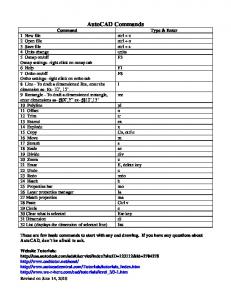
Jun 14, 2010 ... AutoCAD Commands. Command. Type & Enter. 1 New file ctrl + n ... 32 List (
displays the dimension of selected line) list. These are few basic ...
Copyright and Technical Support. Multi-Tech Systems, Inc. CDMA Wireless AT
Commands - PN S000294D. 2. AT Commands for CDMA Wireless Modems.
Jul 15, 2003 ... Multi-Tech Systems, Inc. GSM Wireless AT Commands - PN S000293B. 2 ...
Table of Contents for AT Commands for GSM Wireless Modems.
Jun 2, 2010 ... a license to download and/or print a copy of this document. Any rights ... go-to-
market advice, moderated discussion forums offering free technical support and a
Wiki ... W580i, W580c. W595 ...... Cellular result codes (+CRING).
Developers guidelines June 2010
AT commands for Sony Ericsson phones
Developers guidelines | AT commands
Preface Purpose of this document The Developers guideline for AT commands is designed to give the reader a deeper insight into how to design applications with AT commands supported by mobile phones. The information here is not relevant for the day-to-day operation of the phone. This is described in the User guide supplied with the mobile phone. This document is for advanced users who require detailed information in order to: • Develop new communications software. • Add the mobile phone to a list of compatible modems in an application. • Adjust the settings of their mobile phones. People who can benefit from this document include: • • • • • •
Application providers Content providers Content aggregators Operators and service providers Software developers Business decision-makers
It is assumed that the reader has a basic understanding of AT commands.
These Developers guidelines are published by:
This document is published by Sony Ericsson Mobile Communications AB, without any warranty*. Improvements and changes to this text necessitated by typographical errors, inaccuracies of current information or improvements to programs and/or equipment, may be made by Sony Ericsson Mobile Communications AB at any time and without notice. Such changes will, however, be incorporated into new editions of this document. Printed versions are to be regarded as temporary reference copies only.
*All implied warranties, including without limitation the implied warranties of merchantability or fitness for a particular purpose, are excluded. In no event shall Sony Ericsson or its licensors be liable for incidental or consequential damages of any nature, including but not limited to lost profits or commercial loss, arising out of the use of the information in this document.
Sony Ericsson Developer World At www.sonyericsson.com/developer, developers find the latest technical documentation and development tools such as phone White papers, Developers guidelines for different technologies, Getting started tutorials, SDKs (Software Development Kits) and tool plugins. The Web site also features news articles, go-to-market advice, moderated discussion forums offering free technical support and a Wiki community sharing expertise and code examples. For more information about these professional services, go to the Sony Ericsson Developer World Web site.
Document conventions Products Sony Ericsson mobile phones are referred to in this document using generic names as in the table below. In this document, the chapter “AT commands” contains command specifications valid for the majority of phones mentioned. Added, deleted or changed commands for groups of phones are specified in appendices as in the rightmost column of the table. Generic names Series
Sony Ericsson mobile phones
Appendix
Aino™
Aino™ U10i, Aino™ U10a
4
C510
C510, C510c, C510a
3
C702
C702, C702c, C702a
2
C901
C901, C901a, C901 GreenHeart™
3
C902
C902, C902c
2
C903
C903, C903a
3
C905
C905, C905c, C905a
3
Cedar
Sony Ericsson Cedar™ J108i, Sony Ericsson Cedar™ J108a
4
Elm
Sony Ericsson Elm™ J10, Sony Ericsson Elm™ J10i2
4
G502
G502, G502c
1
G705
G705, G705u
3
Hazel
Sony Ericsson Hazel™J20, Sony Ericsson Hazel™J20i
4
Jalou™
Jalou™ F100i, BeJoo™ F100i (French market)
3
3
June 2010
Developers guidelines | AT commands
Generic names Series
Sony Ericsson mobile phones
Appendix
K530
K530i
K550
K550i, K550c
K610
K610i, K610c, K618i
K630
K630i
1
K660
K660i
1
K770
K770i
K790
K790i, K790c, K790a
K800
K800i, K800c
K810
K810i, K818c
K850
K850i, K858c
1
Naite™
Naite™ J105i, Naite™ J105a
3
Pureness™
Xperia™ Pureness™ X5, Xperia™ Pureness™ X5i
3
S500
S500i, S500c
T650
T650i, T658c
T700
T700
2
T707
T707, T707a
3
T715
T715, T715a
3
V640
V640i
1
W350
W350i, W350c
W380
W380i, W380c
W508
W508, W508c, W508a, W518a
W580
W580i, W580c
W595
W595, W595s
W610
W610i, W610c
W705
W705, W705u
3
W715
W715
3
W710
W710i, W710c
W760
W760i, W760c
W830
W830i, W830c
W850
W850i, W850c
W880
W880i, W888c
3
2
2
4
June 2010
Developers guidelines | AT commands
Generic names Series
Sony Ericsson mobile phones
Appendix
W890
W890i
1
W902
W902
2
W910
W910i, W908c
1
W980
W980i
2
W995
W995, W995a
4
Yari™
Yari™ U100i, Yari™ U100a
4
Z310
Z310i, Z310a
Z555
Z555i, Z555a
Z610
Z610i
Z710
Z710i, Z710c
Z750
Z750i
1
Z770
Z770i
2
Z780
Z780i, Z780a
2
Z780
Z780i, Z780a
2
Zylo
Sony Ericsson Zylo™ W20, Sony Ericsson Zylo™ W20i
4
Typographical conventions The standard text in this manual is modified to distinguish between the text displayed on the screen, typed instructions and examples of command dialogue. The distinctions are as follows: • Typed commands and option values are written in bold text; for example: S2=; =0-127. • Any key strokes are written in bold text in brackets; for example . • Examples of command dialogue, including keyboard entries and on-screen responses, are written in Courier text. • The default parameter setting used by a command is indicated by the text “Default”.
5
June 2010
Developers guidelines | AT commands
Trademarks and acknowledgements GreenHeart, Aino, BeJoo, Jalou, Naite, Pureness, Sony Ericsson Cedar, Sony Ericsson Elm, Sony Ericsson Hazel, Sony Ericsson Zylo, Xperia and Yari are trademarks or registered trademarks of Sony Ericsson Mobile Communications AB. Windows is either a trademark or registered trademark of Microsoft Corporation in the United States and/or other countries. Bluetooth is a trademark or registered trademark of Bluetooth SIG Inc. The IrDA Feature Trademark is owned by the Infrared Data Association and is used under licence there from. Other product and company names mentioned herein may be the trademarks of their respective owners.
Document history Change history 2007-12-04
Doc. No. 1206-6103.1
First version published on Developer World
2008-01-20
Doc. No. 1206-6103.2
Second version. Information about W350, W760 and Z555 series added
2008-02-20
Doc. No. 1206-6103.3
Third version. Information about C702, C902, W980 and Z770 series added
2008-04-20
Doc. No. 1206-6103.4
Fourth version. Minor revision
2008-05-20
Doc. No. 1206-6103.5
Fifth version. Information about G502 and Z780 series added
2008-09-09
Doc. No. 1206-6103.6
Sixth version. Information about C905, G705, T700, W595 and W902 series added
2008-10-17
Doc. No. 1206-6103.6 (rev. B)
Sixth revised version. New document template
2008-11-09
Doc. No. 1206-6103.7
Seventh version. Information about W705 series added
2009-01-08
Doc. No. 1206-6103.8
Eighth version. Information about C510 and W508 series added
2009-02-15
Doc. No. 1206-6103.9
Ninth version. Information about C901, C903, W715 and W995 series added
6
June 2010
Developers guidelines | AT commands
Change history 2009-03-26
Doc. No. 1206-6103.10
Tenth version. Information about T707 series added
2009-05-28
Doc. No. 1206-6103.11
Eleventh version. Information about Aino™ and Yari™ series added
2009-06-25
Doc. No. 1206-6103.12
12th version. Information about Naite™ and T715 series added
2009-08-12
Doc. No. 1206-6103.13
13th version. Information about Jalou™ series added
2009-10-26
Doc. No. 1206-6103.14
14th version. Information about Pureness™ phones added
2009-12-14
Doc. No. 1206-6103.15
15th version. Information about Elm and Hazel series added
2010-04-13
Doc. No. 1206-6103.16
16th version. Information about Zylo series added
2010-06-15
Doc. No. 1206-6103.17
17th version. Information about Cedar series added
7
June 2010
Developers guidelines | AT commands
Contents Overview ....................................................................................................................10 Introduction .............................................................................................................10 Result and error codes ............................................................................................11 AT commands .........................................................................................................15 AT command list .......................................................................................................20 Result codes ..............................................................................................................25 AT commands ...........................................................................................................27 Ensemble C2: Control and identification .................................................................27 Ensemble C3: Call control .......................................................................................34 Ensemble C4: Interface commands ........................................................................42 Ensemble C6: Data compression ............................................................................52 Ensemble C9: Mode management ..........................................................................55 Ensemble C18: Fax class 1 .....................................................................................56 Ensemble C20: Audio control .................................................................................56 Ensemble C25: GSM 07.10 .....................................................................................57 Ensemble C26: Accessory UI ..................................................................................59 Ensemble C27: Accessory UI ..................................................................................60 Ensemble C38: Bluetooth commands ....................................................................81 Ensemble S1: GSM DTE-DCE interface ..................................................................89 Ensemble S2: Call control .......................................................................................89 Ensemble S3: GSM data/fax ...................................................................................94 Ensemble S4: Extended error reporting ..................................................................97 Ensemble S5: GSM HSCSD ....................................................................................98 Ensemble S6: GSM network services ...................................................................104 Ensemble S7: GSM USSD ....................................................................................131 Ensemble S8: GSM facility lock ............................................................................134 Ensemble S9: Mobile equipment, control and status ...........................................139 Ensemble S10: GSM mobile equipment error control ..........................................175 Ensemble S11: SMS and PDU mode ....................................................................176 Ensemble S15: GPRS/packet domain ..................................................................191 Ensemble S16: Phonebook ...................................................................................218 Ensemble S18: GSM clock, date and alarm handling ...........................................224 Ensemble S19: GSM subscriber information ........................................................228 Ensemble S20: Ericsson specific AT commands for GSM ...................................229 Ensemble S26: Voice control ................................................................................233 Ensemble S27: OBEX ............................................................................................235 Ensemble S29: WAP browser ...............................................................................236 Ensemble S34: Internet account commands ........................................................238 Ensemble S35: Sony Ericsson commands ...........................................................272 OBEX Formats .......................................................................................................300 Appendix 1 ...............................................................................................................308 Added AT commands ...........................................................................................309 Updated AT commands ........................................................................................310 Appendix 2 ...............................................................................................................313 Added AT commands ...........................................................................................314 Updated AT commands ........................................................................................315
8
June 2010
Developers guidelines | AT commands
Appendix 3 ...............................................................................................................318 Added AT commands ...........................................................................................319 Updated AT commands ........................................................................................322 Appendix 4 ...............................................................................................................325 Added AT commands ...........................................................................................326 Updated AT commands ........................................................................................330 Index .........................................................................................................................333
9
June 2010
Developers guidelines | AT commands
Overview Introduction This document describes the operation of AT commands supported by Sony Ericsson phones. This reference document is helpful for advanced users who require detailed information in order to: • Develop new communications software. • Add the mobile phone to a list of compatible modems in an application. • Adjust the settings of their mobile phones.
Communications programs Please refer to the User guide and support information found on www.sonyericsson.com for instructions on the installation and use of the Sony Ericsson built-in modem software drivers.
Configuring third-party communications programs If you want to use a communications program which does not include the Sony Ericsson built-in modem in the list of supported hardware, the following options are suggested: Configure for V.25ter The built-in modem supports the V.25ter command set. If your communications program can generate and support a V.25ter command, the built-in modem does not require the installation of a specific driver. Locate a mobile phone modem driver A Mobile Phone Modem driver for the communications program may be available on either the Sony Ericsson disk supplied with the phone or from one of the online services, for example, the support pages on www.sonyericsson.com Configure the data communications program manually To configure your data communications program manually: 1. Select a generic mobile phone modem driver from the list. 2. Set the Init string to AT&F 3. Set the optional setup string to Asynchronous RLP: AT+CBST=0,0,1
10
June 2010
Developers guidelines | AT commands
Result and error codes Result codes When you send a command from your PC or PDA to the built-in modem, the response is terminated by a result code, which is shown on the screen of the sending device. This code is used to confirm correct operation or to identify any problem with the command. There are two types of result codes: • Final result codes related to the operation of AT commands • Result codes associated with call connections
Final result codes from AT commands The built-in modem always terminates each response to an AT command with a final result code: OK
The command(s) and any specified parameters were valid and the command has completed execution.
Some AT commands are not relevant to the built-in modem operations or can only be set to one parameter value. For completeness and to allow the parameter to be read, some of these commands are supported but not implemented. Calling a command of this type produces the OK result code but does not cause any change to the built-in modem. ERROR
An error has occurred during the command processing. This could arise because: • There is a fault in the command syntax • One or more parameters are outside the permitted range • The command you issued is not implemented in the built-in modem • The command is not appropriate to the service • Of the class the built-in modem is operating in
When an error is reported, the ERROR message is preceded by a copy of the text response from the last valid AT command. This is shown in the following example: Valid command:
AT+CBC=?
Response:
+CBC:(0,2),(0-100) OK
Invalid command:
AT+CBC=?;+FCLASS=3
Response:
+CBC:(0,2),(0-100) ERROR
11
June 2010
Developers guidelines | AT commands
Result codes from call connections During online operation of the telephone, result codes inform you about the progress of call connections: CONNECT
A connection has been established and the data rate is shown.
BUSY
The number you called is engaged.
NO DIALTONE
Unable to establish the initial connection.
NO CARRIER
A connection could not be established or an existing connection has been lost.
RING
There is an incoming call. This is not a consequence of local activity and is referred to as an unsolicited result code.
Format of the result codes The result codes described above are in verbose format. You can command the builtin modem to display result codes in verbose or numeric format or you can switch them off completely. To switch between verbose and numeric format, refer to the use of the ATV command on page 46. To switch the display of result codes on or off, refer to the use of the ATQ command on page 46.
Error codes The +CME ERROR result codes indicate an error relating to the functionality of the builtin modem or mobile phone and replace the final result code ERROR when enabled by the AT+CMEE command.
Report mobile phone failure (+CME) +CME ERROR: 0
Phone failure
+CME ERROR: 1
No connection to phone
+CME ERROR: 2
Phone-adaptor link reserved
+CME ERROR: 3
Operation not permitted
+CME ERROR: 4
Operation not supported
+CME ERROR: 5
PH-SIM PIN required
+CME ERROR: 6
PH-FSIM PIN required
+CME ERROR: 7
PH-FSIM PUK required
+CME ERROR: 10
SIM card not inserted
+CME ERROR: 11
SIM card PIN required
+CME ERROR: 12
SIM card PUK required
+CME ERROR: 13
SIM card failure
+CME ERROR: 14
SIM card busy
+CME ERROR: 15
SIM card wrong
12
June 2010
Developers guidelines | AT commands
+CME ERROR: 16
Incorrect password
+CME ERROR: 17
SIM PIN2 required
+CME ERROR: 18
SIM PUK2 required
+CME ERROR: 20
Memory full
+CME ERROR: 21
Invalid index
+CME ERROR: 22
Not found
+CME ERROR: 23
Memory failure
+CME ERROR: 24
Text string too long
+CME ERROR: 25
Invalid character in text string
+CME ERROR: 26
Dial string too long
+CME ERROR: 27
Invalid characters in dial string
+CME ERROR: 30
No network service
+CME ERROR: 31
Network timeout
+CME ERROR: 32
Network not allowed – emergency calls only
+CME ERROR: 40
Network personalisation PIN required
+CME ERROR: 41
Network personalisation PUK required
+CME ERROR: 42
Network subset personalisation PIN required
+CME ERROR: 43
Network subset personalisation PUK required
+CME ERROR: 44
Service provider personalisation PIN required
+CME ERROR: 45
Service provider personalisation PUK required
+CME ERROR: 46
Corporate personalisation PIN required
+CME ERROR: 47
Corporate personalisation PUK required
+CME ERROR: 100
Unknown
Report operational/access failure (+CMS) The +CMS ERROR result codes indicate an error relating to the built-in modem, mobile phone or network relating to the Short Message Service (SMS). This replaces the final result code ERROR. +CMS ERROR: 0...127
+CMS ERROR: 256...511 Values in range 256...511 are reserved +CMS ERROR: 512
Manufacturer specific
Service report (+CR) When a data connection is being established, the +CR messages are sent to the PC before the final result code CONNECT. Use AT+CR to enable these messages. +CR: ASYNC
Asynchronous transparent
+CR: SYNC
Synchronous transparent
+CR: REL ASYNC
Asynchronous non-transparent
+CR: REL SYNC
Synchronous non-transparent
Cellular result codes (+CRING) The +CRING messages replace the unsolicited result code RING and provide more information about the type of the incoming call. Use AT+CRC to enable these messages. +CRING: ASYNC
Asynchronous transparent
+CRING: SYNC
Synchronous transparent
+CRING: REL ASYNC
Asynchronous non-transparent
+CRING: REL SYNC
Synchronous non-transparent
+CRING: FAX
Facsimile
+CRING: VOICE
Normal voice
14
June 2010
Developers guidelines | AT commands
AT commands Introduction to AT commands This chapter describes how AT commands are used to exchange information with the phone, the built-in modem and Bluetooth module. The AT commands are listed at the end of this chapter. For a description of each command, refer to “AT commands” on page 27. You use AT commands to: • Configure the phone to connect via USB cable, infrared port, Bluetooth or the system bus. • Configure the modem to connect via USB cable, infrared port, Bluetooth or the system bus. • Request information about the current configuration or operational status of the phone or the modem. • Test availability in the phone or modem and, when applicable, request the range of valid parameters for an AT command.
Built-in modem operating modes The built-in modem can be set in any one of the following three modes of operation: Offline command mode:
When first switched on, the built-in modem is automatically placed in offline command mode and is then ready to receive AT commands.
Online data mode:
This allows normal operation of the built-in modem, to exchange data or facsimile with a remote modem.
Online command mode:
This allows sending AT commands to the built-in modem while still remaining connected to the remote modem.
Changing the built-in modem operating mode The following illustration summarises the methods that are used to switch between the three built-in modem operating modes:
15
June 2010
Developers guidelines | AT commands
Operating in offline command mode Switch on
Offline Command Mode Exchange AT command data between computer and built-in modem
Dial
Answer
ATD
ATA
Lose carrier or lose IR link or press “No” button (or pull DTR low *) or ATH
Lose carrier or lose IR link or press “NO” button (or pull DTR low *)
Online Data Mode Exchange data or facsimile with a remote modem
+++AT (or pull DTR low *)
ATO
Online Command Mode Exchange AT command data with the Built-in Modem while staying online
* Pull DTR not available when using cable.
Figure 1. In offline command mode, the built-in modem accepts data as commands and not as normal communications traffic. You enter commands by typing at the PC/ PDA keyboard.
Switching to online data mode To enter online data mode, for data to be exchanged with the modem at the other end of the link, enter the ATD command followed by the telephone number to make the call. Alternatively, typing ATA to answer an incoming call also places the built-in modem in online mode.
16
June 2010
Developers guidelines | AT commands
Switching back to offline command mode Any of the following will return the built-in modem to offline command mode from online data mode: • • • •
Loss of connection (NO CARRIER error) Loss of the link between the built-in modem and your computer Pressing the “NO” button on your mobile phone Pulling DTR low (not available when using cable)
Using AT commands during a data connection To use AT commands while connected to a remote modem in online data mode and maintain connection with the remote modem, first enter online command mode. There are two ways to switch from online data mode to online command mode: • Type the escape sequence “+++” followed by an appropriate AT command. This command must be selected from the options AT, ATE, ATH, ATI, ATQ, ATV or ATX. By using this method, an AT function, such as moving into online command mode, can be performed. For example, switching using +++ATH switches the built-in modem to online command mode. The AT command is executed, causing the connection to be terminated (hang-up executed). Typing the escape sequence “+++” without any following command causes the system to wait one second, switch to online command mode and respond OK; • Pull DTR low after setting AT&D=1.
Switching from online command mode to online data mode To return to online data mode while in online command mode, type: ATO
Switching from online command mode to offline command mode To return the built-in modem to offline command mode from online command mode: • Use any of the methods described in “Switching back to offline command mode” above • Type +++ATH to switch to online command mode and hang up at once.
17
June 2010
Developers guidelines | AT commands
Operating the AT commands In command mode, the following types of commands can be issued: • A set command to adjust the operating parameters of the built-in modem • An execution command to direct action without any need for parameters • A read command to view the current command settings • A test command to view the available command parameters Not all AT commands support all functions listed above. The descriptions in “AT commands” on page 27 list the functions available for each AT command.
1. Entering a set command The standard format for entering a set command is: AT= where
AT
Notifies the built-in modem that a command is being entered.
The name of the command being entered.
The values to be used by the command.
All command lines are terminated by pressing the (Return or Enter) key.
Note: All command lines are completed by pressing the key on the computer keyboard. For the remainder of this manual, appropriate use of the key is assumed. To set the built-in modem to operate with autobaud over an asynchronous connection, the command line would be: AT+CBST=0,0,1 However, many commands also have default values. For example, the above command can be entered as: AT+CBST=,,1 Default values used by the commands are indicated by bold text in the following descriptions. When the parameter is a character string, for example, “”, then the value should be entered between quotes, for example, “Peter”. Optional parameters are shown in square brackets, for example, [].
18
June 2010
Developers guidelines | AT commands
2. Entering an execution command Execution commands are very similar to set commands. They usually do not require any parameters and are used to obtain information about the mobile phone or built-in modem or to execute an event. For example, to find out information about the mobile phone battery, enter the +CBC command: AT+CBC The built-in modem responds: CBC: 0,60 indicating that the mobile phone battery is connected (0) and that the remaining charge is 60%. To answer an incoming call, you execute the A command: ATA
3. Using read command to view command settings To check the current settings of a command, use the ? option. For example, to check the current settings of the +CBST command, enter: AT+CBST? If CBST has been set according to the previous example, the settings are displayed as +CBST: 0,0,1
4. Using test command to request command help To test the availability of a command and the range of parameters, use the =? option with the command. For example, to check the parameters available to the command line in the example above, enter: AT+CBST=? The line: +CBST: (0,4,6,7,68,70,71),(0),(1) is displayed indicating the range of valid entries that can be set for the parameters , and .
Accessory identification (Bluetooth)...................................................... 274 Accessory class report.......................................................................... 275 Charging control.................................................................................... 277 SE read log............................................................................................ 277 SE ping command................................................................................. 278 SE audio line status............................................................................... 278 SE functionality status (ver. 2)............................................................... 279 SE flash Information .............................................................................. 280 Flash auto exposure setting from ME ................................................... 281 Camera mode indicator to the flash...................................................... 281 Red eye reduction indicator to the flash ............................................... 282 Ready indicator to the ME..................................................................... 282 Sony Ericsson audio parameters .......................................................... 283 Volume level .......................................................................................... 286 Volume indication request..................................................................... 286 Status bar icon ...................................................................................... 287 Antenna identification............................................................................ 287 Speakermode on/off ............................................................................. 288 Text to bitmap converter....................................................................... 288 Sony Ericsson audio video remote control ........................................... 290 Sony Ericsson multimedia information request .................................... 292 .............................................................................................................. 292 .............................................................................................................. 293 Sony Ericsson application..................................................................... 293 Sony Ericsson application indication request ....................................... 294 Sony Ericsson Java comm.................................................................... 295 Sony Ericsson disable USB charge ...................................................... 296 Sony Ericsson accessory battery status ............................................... 296 Sony Ericsson audio video remote control indication request ............. 297 Sony Ericsson global positioning system accessory ............................ 309 Accessory class report.......................................................................... 310 Sony Ericsson global positioning system accessory ............................ 314 Accessory Class Report........................................................................ 315 Sony Ericsson global positioning system accessory ............................ 319 Sony Ericsson time information request ............................................... 319 Sony Ericsson memory card management ........................................... 320 Accessory Class Report........................................................................ 322 Sony Ericsson global positioning system accessory ............................ 326 Sony Ericsson time information request ............................................... 326 Sony Ericsson memory card management ........................................... 327 Sony Ericsson Disable Keylock............................................................. 328 Accessory Class Report........................................................................ 330
24
June 2010
Developers guidelines | AT commands
Result codes *CPII
Call progress information ....................................................................... 41
+ILRR result code .................................................................................. 52 Data compression indication ................................................................. 54 SEMC GUI indication ............................................................................. 78 SEMC session focus indication ............................................................. 80 SEMC menu item indication................................................................... 80 Bluetooth voice recognition activation indication .................................. 86 Gain of microphone indication ............................................................... 86 Gain of speaker indication ..................................................................... 86 Bluetooth setting of in-band ring tone indication................................... 87 Bluetooth input indication ...................................................................... 87 Graphical caller ID presentation............................................................. 88 Mobile equipment error result ................................................................ 92 Service reporting control........................................................................ 92 Call mode indication .............................................................................. 93 HSCSD parameters report result code ................................................ 103 Network registration............................................................................. 122 Calling line identification indication (ver. 2) .......................................... 123 Calling line alpha tag ............................................................................ 124 Connected line alpha tag ..................................................................... 125 Call waiting notification ........................................................................ 125 Supplementary service notification ...................................................... 125 Supplementary service notification ...................................................... 126 Advice of charge call meter notification............................................... 126 Divert function (ver. 2) .......................................................................... 127 Connected line identification indication ............................................... 129 Called line identification presentation .................................................. 129 CUSD indication................................................................................... 133 Keypad event ....................................................................................... 170 Indicator event ..................................................................................... 171 Call monitoring event ........................................................................... 171 SIM application toolkit command sent from SIM................................. 172 SIM application toolkit notify................................................................ 173 Received cell broadcast....................................................................... 189 New message indication ...................................................................... 190 Received message ............................................................................... 190 SMS status report ................................................................................ 190 GPRS event reporting .......................................................................... 216 Network registration reporting ............................................................. 217 Alarm event .......................................................................................... 227 PIN code event..................................................................................... 232 Indication algorithm status (ver. 1) ....................................................... 232 Flash auto exposure setting result code .............................................. 297 Camera mode indicator result code..................................................... 297 Red eye reduction result code ............................................................. 298 Audio line status result code................................................................ 298 Functionality status result code ........................................................... 298 Volume level result code ...................................................................... 298 Sony Ericsson Multimedia Information Indication................................ 299
25
June 2010
Developers guidelines | AT commands
*SEAVRCI *SETIRI *SETIRI
Sony Ericsson audio video remote control indication.......................... 299 Time Information Request Indicator..................................................... 320 Time Information Request Indicator..................................................... 329
26
June 2010
Developers guidelines | AT commands
AT commands Ensemble C2: Control and identification Commands AT
Attention command
Description:
Checks the communication between the phone and any accessory. Determines the presence of a phone.
Execution command:
AT
AT*
List all supported AT commands
Description:
Execution command causes the ME to return one or more lines of AT commands. The command is identical to AT+CLAC
Execution command:
AT*
Response:
[ […]]
Test command:
AT*=? Test if command is supported
Parameter: :
Description
AT ...
AT command
ATZ
Restore to user profile (ver. 2)
Description:
Instructs the DCE to set all parameters to their default values as specified by the user. It uploads a set of parameters set by AT&W. This may include taking into consideration the settings of hardware configuration switches or non-volatile parameter storage (if implemented). If AT&W is not used, ATZ gives the same effect as AT&F and ATZ can be interpreted as ATH&F.
Execution command:
ATZ
Extended format command:
ATZ=
Test command:
ATZ=? Shows if the command is supported.
27
June 2010
Developers guidelines | AT commands
Test command response:
Z: (list of supported s)
Parameter: :
Description
0
User profile to restore
AT&F
Set to factory-defined configuration (ver. 2)
Description:
Instructs the DCE to set all parameters to default values specified by the manufacturer, which may take in consideration hardware configuration and other manufacturer-defined criteria.
Execution command:
AT&F[=]
Test command:
AT&F=? Shows if the command is supported.
Test command response:
&F: (list of supported s)
Parameter: :
Description
0
Resets all settings to factory defaults
ATI
Identification information (ver. 3)
Description:
Causes the DCE to transmit one or more lines of information text, determined by the manufacturer, followed by a final result code. The parameter may optionally be used to select among multiple types of identifying information, specified by the manufacturer. This command provides compatibility with Microsoft Windows 95.
Execution command:
ATI[]
Execution command response: Parameters: :
Description
0
Same information as AT+GMM command (model identification)
1
Software ID
3
Modem model description
5
Active settings
28
June 2010
Developers guidelines | AT commands
Description
7
Modem configuration profile (brief listing of the modem functionality: fax classes, Bluetooth, IrDA, modem type, and so on)
8
DCE hardware type version
9
PnP (Plug and Play) information
10
Same information as AT+GMI command (manufacturer identification)
Description
string type
The total number of characters, including line terminators, in the information text returned in response to this command may not exceed 2048 characters. Note: The information text may not contain the sequence “0” or “OK”, so that DTE can avoid false detection of the end of this information text
:
AT&W
Store user profile
Description:
Stores the current user profile to non-volatile storage.
Execution command:
AT&W[]
Test command:
AT&W=? Shows if the command is supported.
Test command response:
&W: (list of supported s)
Parameter: :
Description
0
Stores current settings in User Profile 0
AT+CLAC
List all available AT commands
Description:
Causes the ME to return one or more lines of AT commands. Note: Only commands available to the user are returned.
Execution command:
AT+CLAC
Response:
[ […]]
Test command:
AT+CLAC=? Test if command is supported
Parameter: :
29
June 2010
Developers guidelines | AT commands
Description
AT ...
Defines the AT command including the prefix AT
AT+CGMI
Request manufacturer identification (ver. 1)
Description:
Causes the phone to return one or more lines of information text , determined by the phone manufacturer, which is intended to permit the user of the ITAE/ETAE to identify the manufacturer of the phone to which it is connected to. Typically, the text will consist of a single line containing the name of the manufacturer, but manufacturers may choose to provide more information if desired.
Execution command:
AT+CGMI
Execution command response: Test command:
AT+CGMI=? Shows if the command is supported.
Parameter: :
Function
Sony Ericsson
Manufacturer name. The total number of characters, including line terminators, in the information text may not exceed 2048 characters. Text must not contain the sequence 0 or OK
AT+CGMM
Request model identification
Description:
Causes the phone to return one or more lines of information text , determined by the phone manufacturer, which is intended to permit the user of the ITAE/ETAE to identify the specific model of the phone to which it is connected to. Typically, the text will consist of a single line containing the name of the product, but manufacturers may choose to provide more information if desired.
Execution command:
AT+CGMM
Execution command response: Test command:
AT+CGMM=? Shows if the command is supported.
Parameters: :
Description
String Example: AAB1022011-BV
A unique 10-character ASCII string, padded with space if needed. The response may include blank characters
30
June 2010
Developers guidelines | AT commands
AT+CGMR
Request revision identification
Description:
Causes the phone to return a string containing information regarding SW version.
Execution command:
AT+CGMR
Execution command response: Test command:
AT+CGMR=? Shows if the command is supported.
Parameter: :
Description
String
An ASCII string containing software revision plus KRC number
AT+CGSN
Request product serial number identification
Description:
Returns the IMEI number of the phone.
Execution command:
AT+CGSN
Execution command response: +CGSN: Test command:
AT+CGSN=? Shows if the command is supported.
Parameter: :
Description
string
Contains the phone IMEI
AT+GCAP
Request modem capabilities list
Description:
Returns a list of valid modem command prefixes.
Execution command:
AT+GCAP
Execution command response: +GCAP: (list of supported s) Test command:
AT+GCAP=? Shows if the command is supported.
Parameter: :
Description
+CGSM
GSM commands
+FCLASS
Facsimile class 1 and 2 commands
31
June 2010
Developers guidelines | AT commands
Description
+DS
V.42 bis compression
AT+GMI
Request manufacturer information
Description:
Causes the DCE to transmit one or more lines of information text, determined by the manufacturer, which is intended to permit the user of the DCE to identify the manufacturer. Typically, the text will consist of a single line containing the name of the manufacturer, but manufacturers may choose to provide more information if desired, for example, address, telephone number for customer service, and so on).
Execution command:
AT+GMI
Execution command response: Test command:
AT+GMI=? Shows if the command is supported.
Parameter: :
Example:
Description
string
The total number of characters, including line terminators, in the information text returned in response to this command may not exceed 2048 characters. Note: The information text must not contain the sequence 0 or OK, so that DTE can avoid false detection of the end of this information text
AT+GMI Sony Ericsson OK AT+GMI=? OK
AT+GMM
Request model identification
Description:
Causes the DCE to transmit one or more lines of information text, determined by the manufacturer, which is intended to permit the user of the DCE to identify the specific model of device. Typically, the text will consist of a single line containing the name of the product, but manufacturers may choose to provide any information desired.
Execution command:
AT+GMM
Execution command response: Test command:
AT+GMM=? Shows if the command is supported.
Parameter:
32
June 2010
Developers guidelines | AT commands
:
Description
String The total number of characters, including line termiExample: nators, in the information text returned in response Sony Ericsson K750i to this command may not exceed 2048 characters. Note: The information text must not contain the sequence “0 ” or “OK”, so that DTE can avoid false detection of the end of this information text. The command returns the phone model number
AT+GMR
Request revision identification
Description:
Causes the DCE to transmit one or more lines of information text, determined by the manufacturer, which is intended to permit the user of the DCE to identify the version, revision level or date, or other pertinent information of the device. Typically, the text will consist of a single line containing the version of the product, but manufacturers may choose to provide any information desired. The response of this command is equal to that of the AT+CGMR command
Execution command:
AT+GMR
Execution command response: Test command:
AT+GMR=? Shows if the command is supported
Parameter: :
Description
String (ASCII)
The total number of characters, including line terminators, in the information text returned in response to this command may not exceed 2048 characters. Note: The information text must not contain the sequence “0” or “OK”, so that the DTE can avoid false detection of the end of this information text
33
June 2010
Developers guidelines | AT commands
Ensemble C3: Call control Commands ATA
Answer incoming call command (ver. 2)
Description:
Answers and initiates a connection to an incoming call.
Execution command:
ATA
Possible responses: CONNECT CONNECT
Description
28800
Connected with data bit rate of 28800 bps (HSCSD)
19200
Connected with data bit rate of 19200 bps (HSCSD)
14400
Connected with data bit rate of 14400 bps (HSCSD)
9600
Connected with data bit rate of 9600 bps
4800
Connected with data bit rate of 4800 bps
2400
Connected with data bit rate of 2400 bps
NO CARRIER
The mobile phone is not registered.
ERROR
If ATA is unsuccessfully executed by the phone.
ATH
Hook control (ver. 2)
Description:
Signals the MS to terminate an active call.
Execution command:
ATH
34
June 2010
Developers guidelines | AT commands
ATD
Dial command (ver. 5)
Description:
Initiates a phone connection, which may be data or voice (phone number terminated by semicolon). The phone number used to establish the connection consists of digits and modifiers or a stored number specification. It is also possible to initiate a phone connection with the use of the alphanumeric field for a phonebook entry location or by the use of the entry location, , itself. AT+CPBS is the recommended command to select memory storage. Note: Only phone and SM (SIM Memory) storage are supported by ATD. If the dial string is followed by a semicolon, this informs the phone that the number is a voice rather than a data number. If the dial string is omitted but the semicolon included the command instructs the phone to do a network detect. If the network is available, “OK” is returned. Aborting an ATD command is accomplished by the transmission from the DTE to the DCE of any character. A single character is sufficient to abort the command in progress. However, characters transmitted during the first 125 milliseconds after transmission of the termination character are ignored to allow for the DTE to append additional control characters, such as line feed after the command line termination character.
Execution command:
ATD[][I][G][;] Originates a call and dials the phone number specified in the command as or does a network detect. ATD>ME[I][G][;] Dials the phone number stored in phone memory and is located by the index . ATD>SM[I][G][;] Dials the phone number stored on the SIM card and is located by the index . ATD>LD[I][G][;] Dials the phone number stored in the Last dialled number list on the SIM card and is located by the index . The most recently dialled number is assumed to have =”1”. ATD>[I][G][;] Originates a call to the phone number corresponding to the alphanumeric field . If possible, all available memories are searched for the correct entry.
35
June 2010
Developers guidelines | AT commands
ATD>[I][G][;] Originates call to phone number in entry location . The AT+CPBS command setting is recommended to be used to select memory storage. Note: Only phone and SM memory storages are supported by ATD. ATDL[I][G][;] Re-dials the last phone number dialled. Execution command response: • • • • • • •
CONNECT CONNECT NO CARRIER ERROR NO DIAL TONE BUSY OK
Parameters: :
Description
“0 1 2 3 4 5 6 7 8 9 * Valid characters for origination # + A B C” D
The D modifier is ignored but is included only for compatibility purposes
W
The W modifier is ignored but is included only for compatibility purposes
,
The comma modifier is ignored but is included only for compatibility purposes
T
The T modifier is ignored but is included only for compatibility purposes
P
The P modifier is ignored but is included only for compatibility purposes
!
The ! modifier is ignored but is included only for compatibility purposes
@
The @ modifier is ignored but is included only for compatibility purposes
: Description CONNECT
Connection is successfully established. Only valid for data connections
CONNECT
Connection is successfully established. Only valid for data connections
NO CARRIER
Unable to establish a connection or the connection attempt was aborted by the user
ERROR
An unexpected error occurred while trying to establish the connection
NO DIALTONE
The mobile phone is being used for a voice call or is not within coverage of the network
36
June 2010
Developers guidelines | AT commands
Description BUSY
The phone number called is engaged. Valid for data and voice connections
OK
Only valid for voice connections
Description
28800
Connected with data bit rate of 28800 bps (HSCSD)
19200
Connected with data bit rate of 19200 bps (HSCSD)
14400
Connected with data bit rate of 14400 bps (HSCSD)
9600
Connected with data bit rate of 9600 bps
4800
Connected with data bit rate of 4800 bps
2400
Connected with data bit rate of 2400 bps
Description
string type
String type value, which should be equal to an alphanumeric field in a phonebook entry in the searched memories. Note: The character specifying which number in the contact entry that should be used must be included in the string. “/H” stands for home number, “/M” for mobile number, and so on. The character set used should be the one selected with AT+CSCS
Description
I or i
Overrides the CLIR supplementary service subscription default value for this call. I = invocation (restrict CLI presentation) and i = suppression (allow CLI presentation). See AT+CLIR
G or g
Controls the CUG supplementary service information for this call. G = enable CUG supplementary service and g = disable CUG supplementary service
:
:
[I] [G]:
ATO
Return to online data mode
Description:
Switch from online command mode to online data mode during an active call. Returns ERROR when not in online command mode.
Execution command:
ATO[]
Parameter: :
37
June 2010
Developers guidelines | AT commands
Description
0
Returns from online command state to online data state
AT+CVHU
Voice hangup control
Description:
Selects whether ATH or “drop DTR” will cause a voice connection to be disconnected or not. “Voice connection” may also refer to alternating mode calls that are currently in voice mode. Note: When = 2, this command must be used in conjunction with the V.25ter, Serial Asynchronous Automatic Dialing and Control, command &D. Otherwise &D is ignored.
Set command:
AT+CVHU=[]
Read command:
AT+CVHU? Displays the current setting.
Test command:
AT+CVHU=? Shows if the command is supported.
Test command response:
+CVHU (list of supported s)
Parameter: :
Description
0
“Drop DTR” is ignored but OK response given. ATH disconnects the call
1
“Drop DTR” and ATH are ignored but OK response is given
2
“Drop DTR” behaves according to &D setting. ATH disconnects the call
AT+CLCC
List current calls
Description:
Returns the list of current calls. If command succeeds but no calls are available, no information response is sent to TE.
Call identification number as described in 3GPP TS 22.030. This number can be used in AT+CHLD command operations
Description
0
Mobile originated (MO) call
1
Mobile terminated (MT) call
Description
0
Active
1
Held
2
Dialling (MO call)
3
Alerting (MO call)
4
Incoming (MT call)
5
Waiting (MT call)
Description
0
Voice
1
Data
2
Fax
9
Unknown
Description
0
Call is not one of multiparty (conference) call parties
1
Call is one of multiparty (conference) call parties
Description
String type
String type phone number in the format specified by
Description
Integer format
Type of address octet (refer to GSM 04.08 section 10.5.4.7)
128
Unknown numbering plan, national/international number unknown
129
ISDN/telephony numbering plan, national/ international unknown
:
:
:
:
:
:
39
June 2010
Developers guidelines | AT commands
Description
145
ISDN/telephony numbering plan, international number
161
ISDN/telephony numbering plan, national number
128–255
Other values refer to GSM 04.08 section 10.5.4.7
Description
String
Alphanumeric representation of corresponding to the entry found in the phonebook. The used character set should be the one selected with command AT+CSCS
Description
Integer
Optional digit type parameter indicating the eMLPP priority level of the call. Values are specified in 3GPP TS 22.067
0–4
Valid values
:
:
AT*CPI
Call progress information
Description:
Activates or deactivates unsolicited result code *CPI:,,,[,][,][,][,] in the ME. Read command reports current setting and current radio access technology used.
Set command:
AT*CPI=
Read command:
AT*CPI?
Read command response:
*CPI:
Test command:
AT*CPI=? Test if the command is supported
Test command response:
*CPI: (list of supported s)
Parameters: :
Description
0
*CPI reporting disabled. Default value
1
*CPI reporting enabled with short list of parameters: ,,,
2
*CPI reporting enabled with extended parameter set
40
June 2010
Developers guidelines | AT commands
Unsolicited result code *CPII
Call progress information
Description:
Enabled by AT*CPI.
Unsolicited result code:
*CPI: ,,,[,[,[,[,]]]]
Parameters: :
:
:
:
:
:
Description
Integer
Call identification number as described in 3GPP TS 22.030
Integer
Description
0
Setup message
1
Disconnect message
2
Alert message
3
Call proceeding message
6
Call connected message
Integer
Description
0
No in-band tones
1
In-band tones
Integer
Description
0
TCH not assigned
1
TCH assigned
Integer
Description
0
Mobile originated call
1
Mobile terminated call
Integer
Description
0
Voice
1
Data
:
41
June 2010
Developers guidelines | AT commands
:
Description
String type
Phone number of format specified by
Integer. Type of address octet (refer GSM 04.08 section 10.5.4.7).
Description
129
ISDN/telephony numbering plan, national/ international unknown. Default value if “+” is not in
145
ISDN/telephony numbering plan, international number. Default value if “+” is in
161
ISDN/telephony numbering plan, national number
128–255
Other values refer GSM 04.08 section 10.5.4.7
Ensemble C4: Interface commands Commands ATE
Command echo (ver. 2)
Description:
Determines if the DCE echoes characters received from the DTE during command state and online command state.
Set command:
ATE[]
Read command:
ATE? Displays the current setting.
Test command:
ATE=? Shows if the command is supported.
Test command response:
E: (list of supported s)
Parameter: :
Description
0
DCE does not echo characters during command state and online command state
1
DCE echoes characters during command state and online command state. Default value
42
June 2010
Developers guidelines | AT commands
ATS0
Automatic answer control
Description:
Defines the automatic answering feature of the modem. A non-zero value specifies the number of rings before the call is answered. Note: The call always answers in the current fax class, regardless of whether the incoming call is voice, data or fax.
Set command:
ATS0=[]
Read command:
ATS0? Displays the current setting.
Test command:
ATS0=? Shows if the command is supported.
Test command response:
S0: (list of supported s)
Parameter: :
Description
0
Disable automatic answer. Default value
1–7
Answer after the specified number of rings
ATS2
Escape sequence character
Description:
Defines the character to be used as the escape sequence character when switching from online data mode to online command mode.
Set command:
ATS2=[]
Parameter: :
Description
0–255
Supported values. Note: If the parameter is set to a value in the range 128–255, the escape sequence detection is disabled
43
Escape sequence character = “+”. Default value
ATS3
Command line termination character (ver. 3)
Description:
This S-parameter represents the decimal IA5 value of the character recognised by the DCE from the DTE to terminate an incoming command line. It is also generated by the DCE as part of the header, trailer and terminator for result codes and information text, along with the S4 parameter. The previous value of S3 is used to determine the command line termination character for entry of the command line containing the S3 setting command. However, the result code issued will use the value of S3 as set during the processing of the command line. For example, if S3 was previously set to 13 and the command line “ATS3=30” is issued, the command line will be terminated with a character (IA5 0/13), but the result code issued will use the character with the ordinal value 30 (IA5 2/14) in place of the .
43
June 2010
Developers guidelines | AT commands
Set command:
ATS3=
Read command:
ATS3? Displays the current setting.
Test command:
ATS3=? Shows if the command is supported.
Test command response:
S3: (list of supported s)
Parameter: :
Description
0–127
Supported values
13
Command line termination character = . Default value
ATS4
Response formatting character (ver. 3)
Description:
This S-parameter represents the decimal IA5 value of the character generated by the DCE as part of the header, trailer and terminator for result codes and information text, along with the S3 parameter. If the value of S4 is changed in a command line, the result code issued in response to that command line will use the new value of S4.
Set command:
ATS4=
Read command:
ATS4? Displays the current setting.
Test command:
ATS4=? Shows if the command is supported.
Test command response:
S4: (list of supported s)
Parameter: :
Description
0–127
Supported values
10
Formatting character = . Default value
ATS5
Command line editing character (ver. 3)
Description:
This S-parameter represents the decimal IA5 value of the character recognised by the DCE as a request to delete from the command line the immediately preceding character.
Set command:
ATS5=
Read command:
ATS5? Displays the current setting.
Test command:
ATS5=? Shows if the command is supported.
Test command response:
S5: (list of supported s)
Parameter: :
44
June 2010
Developers guidelines | AT commands
Description
0–127
Supported values
8
Editing character = (Backspace). Default value
ATS7
Completion connection timeout
Description:
Defines the maximum time allowed between completion of dialling and the connection being established. If this time is exceeded, the connection is aborted.
Set command:
ATS7=[]
Read command:
ATS7? Displays the current setting.
Test command:
ATS7=? Shows if the command is supported.
Test command response:
S7: (list of supported s)
Parameter: :
Description
1–255
Possible timeout values in seconds
50
Timeout value in seconds. Default value
ATS10
Automatic disconnect delay control
Description:
Specifies the amount of time the DCE will remain connected to the line after the absence of received line signal. Note: For mobile phones this is not applicable and the command is ignored by the TE. This command is included for compatibility reasons only.
Set command:
ATS10=[]
Read command:
ATS10? Displays the current setting.
Test command:
ATS10=? Shows if the command is supported.
Test command response:
S10: (list of supported s)
Parameter: :
Description
1–254
Delay, specified in tenths of a second
2
Remains connected for two tenths of a second. Default value
45
June 2010
Developers guidelines | AT commands
ATQ
Result code suppression (ver. 2)
Description:
The setting of this parameter determines whether or not the DCE transmits result codes to the DTE. When result codes are being suppressed, no portion of any intermediate, final or unsolicited result code (header, result text, line terminator or trailer) is transmitted.
Set command:
ATQ[=]
Read command:
ATQ? Displays the current setting.
Read command response:
Q:
Test command:
ATQ=? Shows if the command is supported.
Test command response:
Q: (list of supported s)
Parameter: :
Description
0
DCE transmits result codes. Default value
1
Result codes are suppressed and not transmitted
ATV
DCE response mode (ver. 2)
Description:
Selects either verbose or numeric response codes.
Set command:
ATV[=]
Read command:
ATV? Displays the current setting.
Read command response:
V:
Test command:
ATV=? Shows if the command is supported.
Test command response:
V: (list of supported s)
Parameter: :
Description
0
Display numeric result code
1
Display verbose result code. Default value
Result code (ATV1) Result code (ATV0) Description OK
0
Acknowledges execution of a command
CONNECT
1
A connection has been established. The DCE is moving from command state to online data state
46
June 2010
Developers guidelines | AT commands
Result code (ATV1) Result code (ATV0) Description RING
2
The DCE has detected an incoming call from the network
NO CARRIER
3
The connection has been terminated or the attempt to establish a connection failed
ERROR
4
Command not recognised, command line maximum length exceeded, parameter value invalid or other problem with processing the command line
NO DIALTONE
6
No dial tone detected.
BUSY
7
Engaged (busy) signal detected
NO ANSWER
8
“@” (Wait for Quiet Answer) dial modifier was used, but remote ringing followed by five seconds of silence was not detected before expiration of the connection timer, S7
ATX
Call progress monitoring control
Description:
Defines the format of the CONNECT message and if the BUSY and NO DIALTONE result codes will be used during a data call setup. Not applicable for voice calls.
Set command:
ATX=[] or ATX[]
Read command:
ATX? Displays the current setting. X:
Test command:
ATX=? Shows if the command is supported.
Test command response:
X: (list of supported s)
Parameter: :
Description
0
Neither BUSY nor NO DIALTONE result code is given. No line speed reported together with CONNECT result code
1
As for =0, but reports line speed together with CONNECT result code
2
BUSY result code is not given. NO DIALTONE result code returned if no network. Reports line speed together with CONNECT result code
47
June 2010
Developers guidelines | AT commands
Description
3
BUSY result code given if called line is busy. NO DIALTONE result code is not given. Reports line speed together with the CONNECT result code
4
BUSY result code given if called line is busy. NO DIALTONE result code returned if no network. Reports line speed together with CONNECT result code. Default value
AT&C
Circuit 109 (DCD) control
Description:
Determines the behaviour of the carrier detect signal (CT109).
Set command:
AT&C[=][]
Read command:
AT&C? Displays the current setting.
Read command response:
&C:
Test command:
AT&C=? Shows if the command is supported.
Test command response:
&C: (list of supported s)
Parameter: :
Description
0
DCD always on
1
DCD follows the connection. Default value
AT&D
Circuit 108 (DTR) response
Description:
Controls how the DCE responds when the Data Terminal Ready (DTR) signal (ct 108.2) is changed from on to off condition.
Set command:
AT&D[=][]
Read command:
AT&D? Displays the current setting.
Read command response:
&D:
Test command:
AT&D=? Shows if the command is supported.
Test command response:
&D: (list of supported s)
Parameter: :
Description
0
Ignore. Default value
1
When in online data mode: Switch to online command mode. All other states: Disconnect and switch to offline command mode
48
June 2010
Developers guidelines | AT commands
Description
2
Disconnect and switch to offline command mode
AT+IFC
Cable interface DTE-DCE local flow control
Description:
Defines the flow control between the modem and the computer when in online data mode. No flow control is enabled in any of the command modes.
Set command:
AT+IFC=[,[]]
Read command:
AT+IFC? Displays the current and settings.
Read command response:
+IFC: ,
Test command:
AT+IFC=? Shows if the command is supported.
Test command response:
+IFC: (list of supported s),(list of supported s)
Parameters: :
Description
0
No flow control on DTE
1
Xon/Xoff flow control on DCE. Control characters are removed by the DCE interface
2
RTS flow control on DCE. Default value
3
Xon/Xoff flow control on DCE. Control characters are passed to the remote DCE/DTE
Description
0
No flow control on DCE
1
Xon/Xoff flow control on DTE
2
CTS flow control on DCE. Default value
:
AT+ICF
Cable interface character format (ver. 2)
Description:
This extended-format compound parameter is used to determine the local serial port start/stop (asynchronous) character framing that the DCE will use while accepting DTE commands and while transmitting information text and result code, if this is not automatically determined. AT+IPR=0 forces +ICF=0 (see AT+IPR). Note: Only applicable for RS-232, dummy command on IrDA and USB.
Set command:
AT+ICF=[[,]
Read command:
AT+ICF? Displays the current and settings.
Read command response:
+ICF: ,
49
June 2010
Developers guidelines | AT commands
Test command:
AT+ICF=? Shows if the command is supported.
Test command response:
+ICF: (list of supported s),(list of supported s)
Parameters: :
:
Determines the number of data bits, parity bits and stop bits in the start/ stop frame.
Description
0
Auto-detect
1
8 Data bits, 2 Stop bits
2
8 Data bits, 1 Parity bit, 1 Stop bit
3
8 Data bits, 1 Stop bit. Default value
4
7 Data bits, 2 Stop bits
5
7 Data bits, 1 Parity bit, 1 Stop bit
6
7 Data bits, 1 Stop bit
Determines how the parity bit is generated and checked, if present.
Description
0
Odd
1
Even
2
Mark
3
Space, Default value
AT+IPR
Cable interface port rate
Description:
This numeric extended-format parameter specifies the data rate at which the DCE will accept commands, in addition to 1200 bit/s or 9600 bit/s (as required in v25ter subclause 4.3). It may be used to select operation at rates at which the DCE is not capable of automatically detecting the data rate being used by the DTE. Specifying a value of 0 disables the function and allows operation only at rates automatically detectable by the DCE. The specified rate takes effect following the issuance of any result code(s) associated with the current command line. Note: Only applicable for RS-232, dummy command on IrDA and USB.
Set command:
AT+IPR=[]
Read command:
AT+IPR? Displays the current setting.
Test command:
AT+IPR=? Shows if the command is supported.
Test command response:
+IPR: (list of supported auto detectable s)[,(list of fixed-only s)].
Parameter:
50
June 2010
Developers guidelines | AT commands
:
The value specified will be the rate in bits per second at which the DTE-DCE interface should operate, for example, “19200” or “115200”. If unspecified or set to 0, automatic detection is selected for the range determined by v25ter, subclause 4.3 and the character format is also forced to autodetect, (AT+ICF=0). (bps)
Autodetect possible
Manual setting possible
0 Yes Default value
Yes
300
Yes
Yes
600
Yes
Yes
1200
Yes
Yes
2400
Yes
Yes
3600
Yes
Yes
4800
Yes
Yes
7200
Yes
Yes
9600
Yes
Yes
14400
Yes
Yes
19200
Yes
Yes
28800
Yes
Yes
38400
Yes
Yes
57600
Yes
Yes
115200
Yes
Yes
230400
Yes
Yes
460800
Yes
Yes
AT+ILRR
Cable interface local rate reporting
Description:
Specifies whether or not the +ILRR intermediate result code is transmitted from the DCE to the DTE. The reported represents the current (negotiated or renegotiated) DTE-DCE rate. If enabled, the intermediate result code is transmitted after any modulation, error control or data compression reports are transmitted and before any final result code, for example, CONNECT is transmitted. The is applied after the final result code is transmitted. The DTE-DCE port rate will change only if neither buffered mode nor error controlled means are enabled (+ES=x,0) and if the negotiated carrier rate (+MRR) does not match the current DTE-DCE port rate (set by +IPR command or autodetected from the previous command line).
Set command:
AT+ILRR=
Read command:
AT+ILRR? Displays the current setting.
Test command:
AT+ILRR=? Shows if the command is supported.
Test command response:
+ILRR: (list of supported auto detectable s)
Parameter: :
51
June 2010
Developers guidelines | AT commands
Description
0
Disables reporting of local port rate. (+ILRR: is not transmitted) Default value
1
Enables reporting of local port rate. (+ILRR: is transmitted)
Intermediate result codes +ILRR
+ILRR result code
Description:
Reports cable interface speed and represents the current DTE-DCE rate. This response is enabled by AT+ILRR.
Intermediate result code: +ILRR: [,rx_rate>] Parameter:
Description
Numeric
See command AT+IPR for possible values of
Description
Numeric
Same coding as , used in case RX rate is different from TX rate
Ensemble C6: Data compression Commands AT+DS
Data compression (ver. 3)
Description:
Controls the V.42 bis data compression function, if provided in the phone. Note: This command is only applicable to CS (Circuit Switched) data calls.
Set command:
AT+DS=[[,[,[,]]]]
Read command:
AT+DS? Displays the current , , and settings.
Test command:
AT+DS=? Shows if the command is supported.
52
June 2010
Developers guidelines | AT commands
Test command response:
+DS: (list of supported s),(list of supported s),(list of supported s),(list of supported s)
Parameters: :
:
Specifies the desired direction(s) of operation of the data compression function from the TE point of view.
Description
0
Disable V.42 bis
1
Enable V.42 bis in transmit direction only
2
Enable V.42 bis in receive direction only
3
Enable V.42 bis compression in both directions. Default value
Specifies if the phone should continue to operate if the desired result is not obtained.
:
:
0
Do not disconnect if compression is not negotiated according to direction. Default value
1
Disconnect if compression is not negotiated according to direction
Maximum number of dictionary entries to be negotiated.
Description
512 to 2048
Maximum dictionary size Note: Must be given in multiples of 512
1024
Default value
Maximum string length to be negotiated.
Description
6 to 250
Maximum string length
32
Default value
AT+DR
Data compression reporting
Description:
Controls whether or not the extended-format +DR intermediate result code is transmitted from the phone to the terminal equipment.The +DR: reported represents the current (negotiated or renegotiated) TAETE data compression type. If enabled, the intermediate result code is transmitted after error control negotiation (handshaking), when the TAE has determined which data compression technique will be used (if any) and the direction of operation. Note: This command is only applicable to CS (Circuit Switched) data calls.
Set command:
AT+DR=
53
June 2010
Developers guidelines | AT commands
Read command:
AT+DR? Displays the current setting.
Test command:
AT+DR=? Shows if the command is supported.
Test command response:
+DR: (list of supported s)
Parameter: :
Description
0
Intermediate compression mode reporting disabled. Default value
1
Intermediate compression mode reporting enabled
Intermediate result codes +DR
Data compression indication
Description:
Data compression report. Enabled by using AT+DR.
Intermediate result code: +DR: Parameter: :
Description
NONE
No data compression negotiated
V42B
V.42 bis data compression negotiated
V42B RD
V.42 bis half duplex compression negotiated on received data
V42B TD
V.42 bis half duplex compression negotiated on transmitted data
54
June 2010
Developers guidelines | AT commands
Ensemble C9: Mode management Commands AT+WS46
Mode selection
Description:
Allows an accessory to query and control the cellular protocol mode of a multimode phone. AT+WS46= allows an accessory to set the cellular protocol mode of a multimode phone. The setting remains in effect until another AT+WS46= command is issued, the phone is reset, a call is terminated or the phone itself makes a mode change. Note: Not all cellular protocol modes can be set via AT+WS46=. ERROR is returned if an attempt is made to set an MS into a mode that cannot be set via the system bus. Supported values of are unique for every Sony Ericsson phone product. Any procedures needed to change from the old to the new mode must complete prior to generation of the OK result code.
Set command:
AT+WS46=
Read command:
AT+WS46? Displays the current setting.
Test command:
AT+WS46=? Shows if the command is supported.
Test command response:
WS46: (list of supported s)
Parameter: :
Supported values differ between phone models.
Description
12
GSM Digital Cellular. This value is used for GSM at 900 Mhz, DCS-1800 and PCS-1900 phones
22
Wideband CDMA. This parameter is used by 3G phones
55
June 2010
Developers guidelines | AT commands
Ensemble C18: Fax class 1 Commands AT+FCLASS
Select mode
Description:
Puts the TA into a particular mode of operation (data, fax, voice, and so on). This causes the TAE to process information in a manner suitable for that type of information. Reset + hangup on failed ATA sets mode to class 0, data mode.
Execution command:
AT+FCLASS=
Read command:
AT+FCLASS?
Read command response:
Show list of supported services
Test command:
AT+FCLASS=? Shows if the command is supported.
Test command response:
(list of supported s)
Parameter: :
Description
0
Data modem
Ensemble C20: Audio control Commands AT*ECBP
CHF button pushed (ver. 2)
Description:
This command is used by the cordless handsfree (CHF) to indicate to the phone that a button on the CHF has been pushed.