ATRIUM: Software Architecture Driven by Requirements Francisco Montero Department of Computing Systems, UCLM
[email protected]
Elena Navarro Department of Computing Systems, UCLM
[email protected]
Abstract
scenario connected to a hierarchy of non-functional requirements. These requirements are considered during the design process of development by using design patterns. We think that there is a compelling need to define a more flexible and efficient software development process able to carry out the design and requirement activities in a concurrent way. If software architecture and UI design are interdependent, as Bass and his colleagues have demonstrated [3], we argue that the applicationarchitecture must explicitly address functional and nonfunctional aspects of the design. Architects need to understand the functional requirements, and create a platform that supports these and simultaneously satisfies the non-functional requirements. We propose that software architecture should define not only the technical interactions needed to develop and implement a product, but also its interactions with users. This compelling need constitute one of the main aims of ATRIUM (Architecture Traced from RequIrements applying a Unified Methodology [33]). It is a methodology that has been defined following the Model Driven Development (MDD, [46]) approach to guide the architecture definition by paying special attention to the functional and nonfunctional requirements that must be met by the systemto-be. The proposal here presented wants to provide evidences of how ATRIUM facilitates the construction of software considering quality criteria and the generation of reliable code, earlier in the life cycle while addressing challenges such as: (a) the ability to understand flaws in an application architecture, before code is even written, leading to brittle architectures and applications; (b) the application of patterns, industry standards, or international standards; (c) the proposal of strategies through which software developers are enabled to localize the principles described in standards for specific application contexts; and (d) the description of an application architecture that explicitly address functional and non-functional aspects of the design. This work is structured in the following sections. First, the real-world case study where the proposal was put into practice is presented in section 2, followed by a brief description of the support provided by MORPHEUS in section 3. ATRIUM is introduced in section 4 following
Interactive systems development is a complex process, because many requirements must be considered. Traditionally, functional requirements capture the intended behavior of the system which may be expressed as tasks or functions the system is required to perform. On the other hand, non-functional requirements are concerned with how the application provides the required functionality rather than defining what the application does. Both kinds of requirements are equally important for the final product, but designers try to achieve them by using different mechanisms. This paper introduces ATRIUM, a methodology for developing interactive systems where functional and not functional requirements are considered in a unified and systematically manner by using documented experience in different level of abstraction: interaction, design and architecture. This methodology is standard compliance as the ISO/IEC 25010 is one of the inputs for the process.
1. Introduction Human-Computer Interaction (HCI) and Software Engineering (SE) disciplines have proposed a number of development processes that take into account the particular problems encountered in the development of interactive systems. Some meaningful examples of HCI methodologies are Usability Engineering [36], the Usability Engineering Lifecycle [27], LUCID [51] and Usage-Centered Design [10]. In these proposals, humancentered activities and usability goals are considered and characterized. In the development of many interactive systems, non-functional requirements are important, especially usability features, but previous methodologies are non-systematic and their success depends on the experience of the development team. In the area of SE, several works have been conducted with a view to improving the Unified Modeling Language (UML [49]), such as, IBM-OVID (Object, View, Interaction and Design) [43], WISDOM [29] and UMLi [45]. However, these works do not explicitly address nonfunctional requirements. In this context, U&SA proposal [5][18][24] is an exception. It introduces a list of architecturally-sensitive usability scenarios, being each
an example driven explanation. How HCI issues have been considered in ATRIUM is presented in section 5. Finally, the analysis of ATRIUM in the context of other architectural knowledge proposals, along with the consequences extracted from this analysis is presented in sections 6 and 7, respectively.
the remainder of this work, specifically, on its Robotic Device Control Unit (RDCU). The TeachMover is a durable, affordable robotic arm used for teaching robotic fundamentals because it has been specifically designed to simulate industrial robotic operations.
3. MORPHEUS: tool support 2. Tele-operated systems: our case study Nowadays, it is more and more frequently the case that robots are used to perform tasks in critical domains such as rescue, military battles, mining and bomb detection, scientific exploration, etc. In this context, tele-operated systems have emerged. They try to provide practitioners with an effective communication and interaction medium between robots and humans. Robots work in environments and/or perform tasks that are highly dangerous for humans allowing humans to be away from these areas. These systems are characterized by the use of two basic components in their construction: sensors and actuators. Environmental Friendly and cost-effective Technology for Coating Removal (EFTCoR) is one of these teleoperated systems [21]. The EFTCoR system is a teleoperated platform for non-pollutant hull ship maintenance operations whose main structure is shown in Fig. 1. In this paper, our case study focuses on the Robotic Device Control Unit (RDCU) because it is not only software, but software-intensive. RDCU is in charge of commanding and controlling in a coordinated way the positioning of devices together with the tools attached to them. Every operation has to be scheduled to accomplish strict deadlines. Its architectural definition is highly relevant because of the fact that several constraints have to be satisfied. Our case study exhibits several specific needs in terms of requirements specification, such as, the variability inherent in the family of robots to be handled; the high incidence of non-functional requirements (reliability, performance, safety, usability, etc) which crosscut functional ones; the need to evaluate alternative designs meeting system requirements; and, finally, a large specification where an appropriate organization is unavoidable. In order to exemplify this proposal, the TeachMover [47], a simplified version of the EFTCoR will be used in
Fig. 1 Tele-operation Maintenance Operations
Robotic
System
for
Hull
Nowadays, automation is becoming one of the principal means to achieve greater productivity and higher quality products. For this reason, its introduction in this proposal was compulsory, both to provide support for the meta-modelling and modelling processes and to assist as much as possible in their later exploitation. This led us to the development of a tool called MORPHEUS, a graphical environment for the description of the different models that provides the analysts with an improved legibility thanks to its graphical support. As ATRIUM entails three different models (see Fig. 3), MORPHEUS 1 has also been structured in three different environments: Requirement Environment [33] provides analysts with a requirements meta-modelling work context for describing Requirement Metamodels customized according to the project’s semantic needs. This Environment automatically provides another work context for the description and analysis of Requirement Models according to the active Metamodel. Scenario Environment [32] has been expressly developed to describe the ATRIUM Scenario Model. This Environment facilitates both the graphical description of architectural scenarios meeting the established requirements and their later synthesis to generate the proto-architecture of the system being defined. Software Architecture Environment [39] makes available a whole graphical environment for the PRISMA AO-ADL [40] so that the proto-architecture synthesized from the Scenarios Model can be refined. Fig. 2 shows the main elements of MORPHEUS. The RepositoryManager component is in charge of providing the different environments with access to the repository where the different models and metamodels are stored. The Back-End component allows the analyst to access to the different environments, and to manage the projects he/she creates. Although it is not shown in Fig. 2, each one of the graphical environments (Requirements ModelEditor shown in Fig. 4, Scenario Editor illustrated in Fig. 5, and Architecture Model Editor depicted by Fig. 6) exploits Microsoft Office Visio Drawing Control 2003 [50] for the graphical support. It was selected, because it allows a straightforward management, both for using and 1
Interested readers can download demos of MORPHEUS from www.dsi.uclm.es/personal/elenanavarro/research_atrium.htm
modifying shapes. This feature is highly relevant for our purposes, because all the kinds of concepts that are included in our metamodels can easily have different shapes, thus facilitating the legibility of the models. Every one of the graphical environments (Fig. 4, Fig. 5, and Fig. 6) is structured in three main areas: the Model Explorer, situated on the left to manipulate the model being defined; the Graphical View, situated in the centre of the environments, is used for graphical modelling; and, finally, the stencils placed on the right provides the user with all the concepts described in the metamodels, so that he/she only needs to drag and drop the relevant concept on the graphical view to perform its description in the model being defined. Another component introduced in the development of MORPHEUS was a QVT engine called Medini [28]. This component facilitates the execution of model-to-model transformations (M2M, [14]) (see section 4). In the following section, it will be shown how MORPHEUS provides support to the different activities of ATRIUM. Back-End
Requirements Environment Requirements MetamodelEditor
Scenarios Env.
AnalysisManager
Software Architecture Env.
SynthesisProcessor
ContextLibrary Requirements ModelEditor
ScenarioEditor
proposals. This activity uses as input both an informal description of the requirements stated by the stakeholders, the ISO/IEC 25010.2 Software product Quality Requirements and Evaluation Quality model (SQuaRE, [23]), and catalogues of patterns. As ATRIUM is intended to follow the Aspect Oriented (AO) approach, aspects must be detected and traced from the early stages to implementation. This is why the standard SQuaRE is used as an initial framework for the selection of concerns, providing us with a strategy for the separation of concerns as well. Quality in this international standard is defined as the result of the quality of the system elements (software quality) and their interaction (quality in use). Software quality is to what extent the software product satisfies stated and implied needs when it is used under specific conditions. SQuaRE software quality model defines eight software quality characteristics: functional suitability, reliability, performance efficiency, operability, security, compatibility, maintainability, and transferability. SQuaRE quality in use model defines three characteristics at the system level (usability in use, flexibility in use and safety in use) that can be used to specify and evaluate requirements in terms of software quality in specified contexts of use. In ATRIUM, we are interested in the characteristics defined for the software product quality and for the quality in use.
Architecture ModelEditor
MOFManager
ISO/IEC 25010 Define Goals
EventsHandler EventsHandler
OCLvalidator
RepositoryManager
Fig. 2. An Overview of the MORPHEUS Architecture
4. A brief introduction to ATRIUM The methodology ATRIUM (Architecture Traced from RequIrements applying a Unified Methodology) [33] has been designed for the concurrent definition of requirements and software architecture, providing automatic/semi-automatic support for traceability throughout its application. ATRIUM has been described following the MDD approach facilitating that the analyst can work in a higher abstraction level and providing him/her with automatic support in several stages of the software development process. Fig. 3 shows its three main activities that must be iterated over in order to define and refine the different models. These activities are described as follows: Define Goals. This activity allows the analyst to identify and specify the requirements of the system-tobe by using the ATRIUM goal model [34], which is based on KAOS [15] and the NFR Framework [13]
Informal Requirements
ATRIUM Goal Model
Selected Architectural Style
Define Scenarios
Patterns
Scenario Model
Transformation rules
Synthesize and Transform
protoarchitecture
Fig. 3. An outline of ATRIUM
Fig. 4 shows a partial view of the TeachMover requirements that have been described by means of the ATRIUM goal model during the Define Goals activity. It depicts part of its functional requirements by refining the goal Suitability into several goals. These goals constitute expectations that the system should meet. It
Fig. 4. Partial description of the EFTCoR requirements
can be observed that the RDCU is expected to coordinate its movement, allow different cleaning operations in specific areas, and catch objects. This refinement is performed by using AND (OR) relationships to determine if all (at least one) the subgoals must be satisfied to satisfy the root. These goals are refined into several goals, and finally into requirements. In ATRIUM two kinds of requirements are considered: (a) functional requirements which describe services that the software provides, i.e., the transformations the system performs on the inputs; (b) non-functional requirements which describe conditions or constraints that the software must satisfy. They refer to how the services are provided, for instance, in terms of operability, quality in use, etc. We are highlighting them because they are especially meaningful in terms of software quality. Finally, these requirements are refined into operationalizations, which describe both the design decision (DD) and the decision rationale (DR) made to satisfy the established requirements [30]. For instance, the operationalization “OPE.2” in Fig. 4 establishes as design decision: “To perform the operational movement by allowing the direct access between systems RUC and SUC”. Its associated design rationale establishes: “The direct access facilitates an advantage in terms of the number of operations to be performed, because they are not only limited to the active tool”. It is not until this level when it is clearly established which elements, from either the system or the environment, are responsible for the different tasks. In this sense, ATRIUM follows the Lauesen’s recommendations [26] because premature decisions
would limit our ability to define different systems depending on time, costs, available resources, etc. Both the requirements and the operationalization are related by means of contributions relationships, that denote how the solutions contribute positively and/or negatively to meet the requirements. For example, it can be observed that the operationalizations “OPE.2” and “OPE.3” have a positive impact on the “REQ.6”. However, the former has a positive impact on “REQ4” whereas the latter has a negative impact. It facilitates the analysis of which design decisions have less negative impact on the set of requirements. Table 1. Describing Architectural Styles Architecture Description style Client-server Segregates the system into two applications, where the client makes a service request to the server. Component- Decomposes application based design into reusable architecture functional or logical components that are locationtransparent and expose welldefined communication interfaces. Layered Partitions the concerns of the architecture application into stacked groups (layers). Message-bus A software system that can receive and send messages that are based on a set of known formats, so that
Category Deployment
Structure
Structure Communication
Fig. 5. Describing in the Scenario Environment an Architectural Scenario related to “OPE.2”
n-tier / 3 tier
Objectoriented
Separated presentation
Serviceoriented architecture (SOA)
systems can communicate with each other without needing to know the actual receiver. Segregates functionality into separate segments in a similar way to the layered style, but being each segment a tier located on a physically separate computer. Divides the tasks of an application or system into individual reusable and selfsufficient objects, each containing the data and the behavior relevant to the object. Separates the logic of managing user interaction from the user interface (UI) view and from the data the user works with. Refers to Applications that expose and consume functionality as a service using contracts and messages.
Deployment
Structure
Interaction
Communication
In addition, during this activity the architectural style to be used is selected by considering, specially, the non-functional requirements [33]. An architectural style is a coarse-grained pattern, as those described in Table 1, that provides an abstract framework for a family of systems. An architectural style improves partitioning and promotes design reuse by providing solutions to frequently recurring problems. Their early selection in ATRIUM is due to the fact that the architectural style to be applied to the system-to-be determines if the non-functional requirements will be met or not. In the EFTCoR, the Acroset style was selected as it describes a clear assignment of
responsibilities by specializing the layer style. It identifies four layers: (a) Hardware Layer that is integrated by a set of sensors and actuators, usually implemented by means of hardware components as, for instance, one of the joints of the Teachmover; (b) Simple Unit Controller (SUC) layer controls the actuator and processes the data received from the sensors that are in the layer beneath it. For instance, in the Teachmover there will be a SUC for every joint generating the commands for the actuator according to the information it receives from the sensors; (c) Mechanism Unit Controller (MUC) is at the third level and is defined by means of an aggregation of SUCs that it must control according to the information they provide and the control policy it implements, as for instance, in the Teachmover, it is in charge of controlling the arm of the robot; (d) finally, the last layer is called Robot Unit Controller (RUC) and controls the whole behaviour of the robotic unit by managing the set of MUCs below it. For instance, it controls the wrist and the arm in the Teachmover. Define Scenarios. This activity focuses on the specification of the ATRIUM Scenario Model, that is, the set of Architectural Scenarios that describes the system’s behaviour under certain operationalization decisions [31]. Each ATRIUM Scenario identifies the architectural and environmental elements that interact to satisfy specific requirements and their level of responsibility. An extension of the metamodel UML 2.0 Sequence Diagram has been defined in order to describe solutions applicable to functional and nonfunctional requirements [33]. It is worthy of note that this extension allow us both to describe scenarios dealing with architectural elements instead of objects and to provide the needed expressiveness to describe aspectual services.
Fig. 6. Describing the architectural specification for the TeachMover system
For instance, Fig. 5 shows one of the ATRIUM identified scenarios associated to the operationalization “OPE.2”. It can be seen that the recommendations established by the DD have been followed, as the communication between the systems RUC and SUC has been directly established by means of components and connectors. In order to maintain the traceability, every time an ATRIUM scenario is defined a relationship specifiedBy must be specified between it and its operationalization. For instance, Fig. 5 illustrates how the scenario is associated to the Operationalization “OPE.2” by means of a contention relation in the Model Explorer situated on the left in the MORPHEUS Scenario Environment. Every operationalization, which was selected to be applied on the system-to-be, is specified in the Model Explorer of the Scenario Environment. It allows the analyst to structure the scenario model according to these design decisions. This facilitates that the traceability can be easily maintained between the goal model and the scenario model. Synthesize and Transform. This activity has been defined to generate the proto-architecture of the specific system [30]. With this purpose, it synthesizes the architectural elements from the ATRIUM scenario model, which build up the system-to-be, along with its structure. This proto-architecture is a first draft of the final description of the system that can be refined in a later stage of the software development process. This activity has been defined by applying M2M techniques, specifically, using the QVT Relations language [38] to define the necessary transformations to generate the proto-architecture. The advantages are twofold. First, the Architectural Style selected during the Define Goal activity can be automatically applied [33] so that the constraints imposed by the Style are satisfied. Second, the analyst can generate the protoarchitecture he/she deems appropriate for his/her
purposes. This activity can be performed when at least one scenario has been defined, and thanks to the incrementality feature of QVT as new architectural scenarios are defined the proto-architecture can be updated to introduce the necessary changes. It must be pointed out that ATRIUM is independent of the Architectural Metamodel used to describe the proto-architecture. The Synthesize and Transform stage has been defined using M2M techniques whereby the analyst only has to describe the needed transformations to instantiate the needed architectural metamodel he/she deems appropriate. Currently, the set of transformations [33] to generate the proto-architecture instantiating the PRISMA architectural metamodel [40] has been defined because a compiler to generate code from PRISMA models already exists. In case the analyst selects PRISMA as the target architectural metamodel to be instantiated, MORPHEUS provides her/him with an environment (Fig. 6) to refine the generated proto-architecture. This architectural environment facilitates the modification of the protoarchitecture by means of graphical utilities [39].
5. ATRIUM and Interactions Patterns There are many references available on the high-level principles of good interface design. Designers know that they ought to use direct manipulation, immediate feedback, proper affordances, protection from accidental mistakes, friendly error messages, and so on. But if they are novice designers, it is hard even to remember all these principles, and use them effectively. Even sometimes, it is difficult to make the tradeoffs among these principles when conflicts among them arise. In this context the exploitation of patterns emerge as a proper proposal helping them in the design process. Patterns are documented experiences and structural and behavioural features that improve the quality of something. As such,
«systemFrame» RobotRUC. Move(Wrist, step,speed)
Robot
«systemFrame» WristSUC. wristmovejoint(NewleftHalfSteps, NewrightHalfSteps,speed)
WristCnct
WristActuator
WristSensor
(A)
«systemFrame» RobotRUC. Move(Wrist, step,speed)
(B)
«systemFrame» WristSUC. wristmovejoint(NewleftHalfSteps, NewrightHalfSteps,speed)
Robot
Wrist
WristCnct
WristActuator
WristSensor
Wrist
Operator
Operator
undo()
wristmovejoint(step,speed)
C{Persitence} restoreFromMemento(joint, previousX, previousY, previousZ)
getCurrentPosition(currentX, currentY, currentZ)
alt C{Persitence} addMementoStep(wrist, currentX, currentY)
[joint=wrist] wristmovejointPos(previousX, previousY, , previousZ, speedDefault)
wristmovejoint(newleftHalfSteps, newrightHalfSteps, speed)
wristmovejointPos(previousX, previousY, , previousZ, speedDefault)
wristmovejoint(newleftHalfSteps, newrightHalfSteps, speed)
wristmovejointPos(previousX, previousY, , previousZ, speedDefault)
wristmovejoint(newleftHalfSteps, newrightHalfSteps, speed)
move(Ok)
move(Ok)
move(Ok)
move(Ok) move(Ok)
move(Ok) move(Ok)
move(Ok)
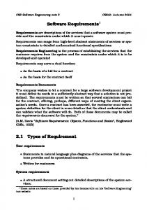
Fig. 7. (A) ATRIM Scenario modified to apply the Memento pattern; (B) ATRIUM scenario added to apply Memento pattern
patterns are descriptions of best practices within a given design domain. In ATRIUM, we use several kinds of patterns, concretely interaction and design patterns. Interaction patterns are structural and behavioral features that improve the quality in use of something –a user interface, a web site or, in our case, an object-oriented program. As such, interaction patterns can be a description of best practices within a given design domain, examples of these patterns can be found in [48], [52], [16]. These patterns cannot be to be put into practice by designers or by CASE tools in an automatic way because they are usually documented by using natural language. Therefore, additional information is needed in order to use them effectively. With this aim, the exploitation of Design patterns [19] emerges as a proper approach to describe solutions implementation for interaction pattern. Normally, interaction patterns are gathered using pattern languages or catalogues that can be organised by using quality criteria. In ATRIUM SQuaRE international standard, introduced in section 4, is used to identify quality goals that the system-to-be needs. SQuaRE defines eight software quality characteristics. In this paper, we will focus on the operability criterion - to what extent the software product can be understood, learned, and used and is attractive to the user when used under specified conditions. Under this quality criterion several subcriteria are considered: learnability, ease of use, appropriateness, recognisability, technical accessibility, helpfulness, attractiveness, and compliance. These quality sub-criteria are specially related to non-functional requirements that should be considered when developing an interactive system, such as the EFTCoR. In our case study, operability is an important criterion. As has been stated, this criterion is refined as ease of use to what degree the software product makes easy to operate and control it by users. It is in this context when interaction patterns can be useful. There are many interaction patterns related with ease of use criterion, for
instance, if designers in the development process detect an archetypical interaction then pattern collections can be considered, such as Common Ground [48]. In this collection, designers can find some supporting documented suggestions, as for instance: Go Back One Step, Go Back to a Safe Place, Actions for Multiple Objects, Forgiving Text Entry or Remembered State. These interaction patterns are user requirements compliant, but, as stated above, their original description is not useful for its application. In order to solve this deficiency, other experience and patterns can be used, design patterns [19]. These patterns can play an active role by describing solutions that satisfy the needs described by the interaction patterns. In addition, these patterns can be easily described in a way that allow one to automatically apply them. Taking into account the EFTCoR, we can observe in Fig. 4 that operability was stated as one of the goals to be satisfied by the system-to-be (“GOA.78”). This goal was refined into ease of use (“GOA.79”) following the SQuaRE recommendations. In the EFTCoR system, the functional requirements were analysed to establish which ones could be affected for this quality criterion. For instance, it was determined that the requirement “REQ. 6 Move work point to a target from its current position” is affected by this quality criterion. As was stated before, one of the Tidwell’s recommendations to achieve that criterion is the introduction of Go Back One Step (also called undo as we will use in the following). For this reason, a new requirement “REQ.127” was specified in the goal model to establish that this operation of the system can be undone whenever the user demands it. As can be observed in Fig. 4, a croscutting relationship among them was described to determine that “REQ.127” is constraining “REQ. 6”. In order to implement a solution for the requirement “REQ.127”, the Memento design pattern [19] was selected and specified as operationalization “OPE.152”. Both requirement and
operationalization are related by means of a contribution relationship as Fig. 4 depicts. Memento design pattern provides a solution for recording the internal state of an element. This is required when implementing undo mechanisms so that users can undo tentative operations or recover from errors. This solution saves state information so that it can be restored later. In this solution, internal quality is considered too, because architectural elements usually encapsulate part or all of their state, making it inaccessible to other element and impossible to save it externally. Exposing this state would violate encapsulation, which can compromise the application's reliability and extensibility. To support undo, an application must be able to revert to the state in which it existed before a user executed an operation. There are at least a couple of ways designer can implement a revert operation. If designer can directly reverse an operation, undo is a simple matter of storing a list of executed operations, each associated with a reversal operation. For example, in our case study where movement of the wrist is supported by the system, operator can undo the movement to a prior position by reverting the operation. If an operator moved the joystick a 360° range from an initial position, undo is a simple matter of providing an opposite movement with the same quantity from the current position. However, sometimes the prior state should be stored because reversing some operations can be too complex or even not feasible. For instance, just consider the vision system of the EFTCoR. It takes random snapshots when a new place is reached by the robot. The control of such application must maintain a complete list of all snapshots to be done. Instead of trying to undo a single snapshot, the simpler approach is to store the complete list of snapshots prior to executing each command. This stored list is the Memento. The Memento is kept along with the associated operation. As was stated in section 4, every operationalization has associated a set of scenarios that describe the behavior of the system according to the made decision. According to the “OPE.127” specified in the EFTCoR, a memento pattern must be applied on the scenario described in Fig. 5. The result of this application is shown in Fig. 7. The initial scenario is modified, as Fig. 7(A) shows, to consider that each time a movement is required to the wrist joint, the current state is stored thanks to a persistence aspect that will contain a service “addmementoToStep()”. This service registers both the joint affected by the movement and its current position. Several alternatives were analyzed to describe this solution as, for instance, that every joint provides this service. However, this will mean some problems when complex operations must be performed as, for example, when the user requests to move the whole arm instead of a specific joint. In this case, the robot would have to register all this operations so that they could be undone.
An additional scenario has been also defined to provide the system with the ability to undo the last operation, as Fig. 7 (B) shows. It can be observed that whenever an “undo()” service is requested to the robot, it retrieves the last operation by using ”restorefromMemento()” to recover which joint was moved along with its previous position, so that the wrist can be backed out. As was stated in section 4, once the ATRIUM scenario model has been (partially) defined we can proceed to the next activity of ATRIUM, that is, synthesize and transform, to generate a draft of the architecture by applying the set of transformation defined in QVT (its whole description can be found in [33]). Fig. 8 shows the result of its application, where we can observe some of the generated architectural elements, systems and components, along with some of the aspects and interfaces generated. «SystemPRISMA» Systems::RobotRUC
PortRobotRUC
«SystemPRISMA» Systems::WristSUC
PortWristSUC
System level PortWristCnct
«ComponentPRISMA» Components::Robot
Component level RobotRUCPersistence +addMementoStep(joint, currentX, currentY, currentZ) +restoreFromMementoStep(joint, previousX, previousY, previousZ)
PortWristSUCInteface +undo() +wristmovejoint(step, speed) +wristmovejoint(newleftHalfSteps, newrightHalfSteps, speed) +move(OK)
Aspects and Interface level
Fig. 8. Partial description of the generated protoarchitecture
6. Related works As was stated above, this work presents a proposal, ATRIUM, and a tool, MORPHEUS, for bridging the gap between the fields of HCI (Human Computer Interaction) and SE (Software Engineering). The SE community focuses on the system perspective: software development is driven by specifications that define the application, including the user interface. The user interface has to meet the functional and usability requirements, but usually the specification of these requirements are more coupled to the system itself than to user preferences. On the contrary, the HCI community focuses on the user perspective. The priority is to ensure that each kind of user can perform a given set of tasks with the application. The software development process is driven by the need to define and validate these requirements and closely depends on the tasks defined and the user’s capabilities and characteristics. In ATRIUM both functional and non-functional requirements are considered. Traditionally, functional requirements gather the intended behavior of the system that may be expressed as tasks or functions it is required to perform. In this sense, a use case defines a goal-
oriented set of interactions between external actors and the system under consideration. Actors are parties outside the system that interact with the system ([49], pp. 2.1132.123). On the other hand, non-functional requirements are the ones that do not appear in use cases. Rather than define what the application does, they are concerned with how the application provides the required functionality [20]. HCI and SE practitioners and researchers have proposed a number of development processes that take into account the particular problems encountered in the engineering of highly interactive systems. Examples of the large number of methodologies are the Star Lifecycle [22], Usability Engineering [36], LUCID (Logical UserCentered Interface Design) method of [47], the Usability Engineering Lifecycle [27] and Usage-Centered Design [10]. In these proposals non-functional requirements, especially usability goals, are considered at the beginning of them but in a non-systematic way and not-standard compliance. Several research works have been conducted whose main aim was to improve the unified modeling language (UML), as for instance, IBM-OVID (Object, View, Interaction and Design) [43], WISDOM [29], and UMLi [45]. However, non-functional requirements are not explicitly addressed in these works. From the SE community, several works have been presented that pursue similar objectives to the ones proposed in this work. The KAOS framework, proposed by Lamsweerde [25], is aimed at supporting the process of requirements elaboration – from the high level goals that should be achieved by the composite system to the operations, objects and constraints to be implemented by the software-, and obtains a first draft of the software architecture. One of the main advantages exhibited by this proposal is its capability to analyze both alternative designs and systems. The main restriction shown by this approach is related to the use of non-functional requirements. They are only used to make decision among several alternatives but they are not as relevant as the functional ones. This is quite controversial because their relevance has been widely recognized, as Bass et al. [6] and Bosch & Molin [8] set out. This lack is also evident in terms of operability requirements. Castro et al. have defined a methodology called TROPOS [12] for guiding the process of system specification from early requirements to a detailed analysis. This methodology includes a set of techniques to generate code executable in the platform JACK (a commercial agent-oriented platform). The requirements are gathered and elicited using the framework called i*, specially used to analyze business goals. In addition, another goal model, based on the NFR Framework, is defined in order to select the Architectural Style applicable to the system-to-be. This is carried out by analyzing the Architectural Styles, represented as operationalizations, according to their contribution to the
identified quality criteria. One of the advantages exhibited by this proposal is that it is a driven requirements proposal, that is, authors state that the same concepts are used throughout the process, avoiding misconceptions. However, some problems emerge because there is not analysis of alternatives in terms of the composing element of the system-to-be. There is not guidance for the analyst in this process either. In addition, there is no mention about how the architecture is generated or about the usability requirements. Rapanotti et al. have described in [42] an extension to the Problem Frames proposal by introducing what they have called Architectural Frames (AFrames). It has been defined to relate the description of the problem to the structure of the solution by combining a problem class and an architecture class (Architectural Styles). The main idea is that the latter can guide the analysis and the decomposition of the former. This solution is amenable to perform iterative development due to the interaction among requirements, architecture, and design: each one informing about the others and vice versa. However, there is no mention of how the synthesis is performed when the number of iteration is greater than one either about how the operability is dealt with. Bruin and Vliet [11] have described a process for the generation of software architecture. They describe the knowledge of both the functionality of the system and the quality requirements in the Feature Space (FS) by using a Feature-Solution graph. They also describe solution fragments at the architectural level, called the Solution Space (SS). In the SS, Use Case Maps (UCM) are defined as realizations of these fragments. The main characteristic of this proposal is its ability to establish traces between the feature space and the solution space, facilitating that both descriptions of the system can be maintained up to date. This proposal introduces Architectural Styles as a decision in the SS along with decision fragments that introduce decisions according to the architectural style and UCMs descriptions. They generate the software architecture as a composition of UCMs. However, authors do not provide any detail about how this generation proceeds so that it finally seems more a manual process than an automatic one as it is proposed in this work. In addition, any attention is paid to operability issues. The work presented by Sanchez et al. in [44] is the only one that deals with the generation of software architecture using a perspective similar to the one presented in this work. They present a process that combines MDD and AOSD to derive Aspect-Oriented Architectures from Aspect-Oriented Requirements models. In their proposal, the functional requirements are modeled as UML scenarios using a profile (that is under definition). Non-functional requirements are modeled independently as parameterized UML diagrams. Once the set of scenarios (both aspectual and functional) have been defined, they are transformed into an Aspect-Oriented
Architecture by means of a set of transformation rules specified using QVT [38]. Specifically, the AO-ADL they have used as target language is CAM [41]. One of the main advantages shown by this proposal is the definition of aspectual scenarios. As these scenarios are parameterized, they can be woven whenever necessary, thereby obtaining a proper management of the crosscutting. However, this proposal does not provide an architectural description that deals with non-functional requirements. Instead, they are introduced at the architectural level as textual constraints because transformations have not been defined to perform this task. These constraints must be resolved at the architectural level to trade-off what architectural mechanisms must be used to address them. Therefore, they do not generate a proto-architecture that meets both functional and non-functional requirements but only the functional ones. In addition, they do not describe a whole process that deals properly with traceability nor it is supported by a tool. In addition, any attention is paid to operability issues.
7. Conclusions and further work In this work, ATRIUM, a MDD methodology to guide the concurrent development from system requirements and software architecture, has been presented. Special attention has been paid to how ATRIUM deals with quality issues because they are considered from the very beginning of its application. With this aim, ATRIUM has been defined as standard quality compliance, especially with SQuaRE, as the requirement specification is conducted considering the criteria identified by the standard as concerns of the system-to-be. It provides us with an additional advantage, that is, the proper separation of the concerns of the system-to-be. Moreover, it has been shown how MORPHEUS provides support to each model and activity of ATRIUM. In addition, useful design experiences (patterns) are also considered in ATRIUM. In order to bridge the gap between requirements and software solutions, interaction patterns and design patterns are jointly used. Interaction patterns are principles of design for user interfaces. However, they cannot be directly implemented because they do not provide the necessary information. With this aim, the proposed strategy has been to exploit design patterns as solutions for their implementation. This idea has been shown using the real-world case study, EFTCoR. Our main goals, introduced at the beginning of this paper, were related to the ability of understanding flaws in application architecture, before code is even written, which can lead to brittle architectures and applications. We consider that these goals are successfully addressed by our proposal, because it has been defined to allow the analyst to evaluate different alternatives, and put them
into practice as we can generate code from the obtained proto-architecture for validation purposes. Finally, an additional issue addressed in this paper is how the description of the application architecture is conditioned by functional and non-functional aspects of the design. It has been shown, how the non-functional requirements act as constraints on the functional ones, determining modification in the identified functional scenarios. Acknowledgments. This work has been funded by the Spanish Ministry of Education and Science under the National R&D&I Program, META Project TIN2006-15175-C05-01 and DESACO TIN2008-06596-C02-01 and by UCLM, Project MDDRehab TC20091111.
References [1] L. Bass, B. E. John, N. Juristo, and M. Sanchez-Segura, Tutorial "Usability-Supporting Architectural Patterns" in Proc. 26th Int. Conf. on Software Engineering, (2004). [2] L. Bass, B. E. John, N. Juristo, and M.-I. Sanchez-Segura, “Usability and software architecture.” Tutorial at the 26th International Conference on Software Engineering, ICSE 2004, Edinburgh, Scotland, (2004). [3] L. Bass, and B. E. John, “Linking Usability to Software Architecture Patterns through general scenarios”, Journal of System and Software, 66, Elsevier, pp. 187-197 (2003). [4] L. Bass, and B. E. John, Supporting the CANCEL Command Through Software Architecture, CMU/SEI2002-TN-021, SEI, CMU, Pittsburgh, PA, (2002). [5] L. Bass, B. E. John, and J. Kates, Achieving Usability Through Software Architecture, CMU/SEI-TR-2001-005 Pittsburgh, SEI, Carnegie Mellon University, http://www.sei.cmu.edu/publications/ (2001). [6] L. Bass, M. Klein, F. Bachmann, “Quality Attribute Design Primitives and the Attribute Driven Design Method”, Proc. 4th International Workshop Software Product Family Engineering (PFE 2001), LNCS 2290, (2001). [7] J. Bosch, and N. Juristo, Tutorial "Designing Software Architectures for Usability," Proc. of the 25th International Conference on Software Engineering, (2003). [8] J. Bosch, P. Molin, “Software Architecture design: evaluation and transformation”, Proc. IEEE Conf. and W. on Eng. of Computer-Based Systems, (ECBS '99), (1999). [9] T. Bosser, and E.-M Melchior. “The SANE toolkit for cognitive modelling and user-centred design.” In Methods and Tools in User-Centred Design for Information Technology, North-Holland, Elsevier Science Publishers, Amsterdam, (1992). [10] L. L. Constantine L. A. D. and Lockwood, Software for Use: A Practical Guide to the Models and Methods of Usage-Centered Design. Addison-Wesley (1999). [11] H. de Bruin and H. van Vliet, Quality-Driven Software Architecture Composition, Journal of Systems and Software, 66(3), pp. 269-284, (2003). [12] J. Castro, M. Kolp, J. Mylopoulos, Towards RequirementsDriven Software Development Methodology: The Tropos Project, Information Systems, pp. 365-389, June 2002.
[13] L. Chung, B. A. Nixon, E. Yu, J. Mylopoulos, NonFunctional Requirements in Software Engineering. Kluwer Academic Publishing, Boston Hardbound (2000). [14] K. Czarnecki, S. Helsen, Classification of Model Transformation Approaches. IBM Systems Journal, 45(3), pp. 621-645 (2006). [15] A. Dardenne, A. van Lamsweerde, S. Fickas: Goal-directed Requirements Acquisition, Science of Computer Programming, 20(1-2), pp. 3-50 (1993). [16] D.K.V. Duyne, J., Landay, and J.I. Hong, The Design of Sites: Patterns, Principles, and Processes for Crafting a Customer-Centered Web Experience. Addison-Wesley Longman Publishing Co., Inc, (2002). [17] R Filman, T Elrad, S Clarke, Aspect-oriented software development, Addison-Wesley, (2004). [18] E. Folmer, and J. Bosch, Architecting for usability. Journal of systems and software, 70(1), pp.61–78, (2004). [19] E. Gamma, R. Helm, R. Johnson, J. M. Vlissides, Design Patterns: Elements of Reusable Object-Oriented Software, Addison Wesley, (1993). [20] Gordon, I. Essential software architecture. Springer-Verlag Berlin Heidelberg. (2006). [21] GROWTH G3RD-CT-00794: EFTCOR: Environmental Friendly and cost-effective Technology for Coating Removal. European Project, 5th Framework Prog. (2003). [22] D. Hix, and H. R. Hartson, Developing User Interfaces: Ensuring Usability Through Product and Process. John Wiley & Sons, New York, OCLC QA76.9U83H59, (1993). [23] ISO/IEC JTC JTC1/SC7 N4098, Software engineeringSoftware product Quality Requirements and Evaluation (SQuaRE) Quality model (2008). [24] N. Juristo, A. M. Moreno, I. Sánchez, Clarifying the Relationship between Software Architecture and Usability. Proc. Software Engineering and Knowledge Engineering (SEKE 2004), (2004). [25] A. van Lamsweerde, “From System Goals to Software Architecture”, Formal Methods for Software Architecture, LNCS 2804, Springer-Verlag, pp. 25-43, (2003). [26] S. Lauesen, Task Descriptions as Functional Requirements. IEEE Software 20(2), pp. 58-65 (2003). [27] D. J. Mayhew, The Usability Engineering Lifecycle: A Practitioner’s Guide to User Interface Design. Morgan Kaufmann Publishers Inc., San Francisco, CA (1999). [28] Medini , QVT Relations, http://projects.ikv.de/qvt . [29] N. J. Nunes, J. F. Cunha, Wisdom: A Software Engineering Method for Small Software Development Companies, IEEE Software, 17(5), pp. 113 – 119, (2000). [30] E. Navarro, C. Cuesta, “Automating the Trace of Architectural Design Decisions and Rationales Using a MDD Approach,” Proc. 2nd European Conference Software Architecture (ECSA 2008), LNCS 5292, (2008). [31] E. Navarro, P. Letelier, I. Ramos: Requirements and Scenarios: playing Aspect Oriented Software Architectures. Proc. 6th IEEE/IFIP Conference on Software Architecture (WICSA 2007), (short paper) (2007). [32] E. Navarro, P. Letelier, D. Reolid, I. Ramos, "Configurable Satisfiability Propagation for Goal Models using Dynamic Compilation Techniques", Advances in Information System Development: New Methods and Practice for the Networked Society, Springer, (2007).
[33] E. Navarro: Architecture Traced from RequIrements applying a Unified Methodology, PhD thesis, Computing Systems Department, UCLM (2007). [34] E. Navarro, P. Letelier, J. A. Mocholí, I. Ramos: A Metamodeling Approach for Requirements Specification, J. of Computer Information Systems, 47(5), 67-77 (2006). [35] E. Navarro, P. Letelier, J. Jaén, I. Ramos, ·Supporting the Automatic Generation of Proto-Architectures,” Proc. 1st European Conference on Software Architecture (ECSA 2007), LNCS 4758, pp. 43-58, (2006) (Best poster award). [36] J. Nielsen, Usability Engineering. Boston, MA: Academic Press Inc. (1993). [37] F. J. Ortiz, D. Alonso, B. Álvarez, J. A. Pastor, “A Reference Control Architecture for Service Robots Implemented on a Climbing Vehicle”, Proc. 10th AdaEurope International Conference on Reliable Software Technologies, York,( 2005). [38] OMG document ptc/05-11-01, QVT, MOF Query/ Views/Transformations. Final adopted specification (2005). [39] J. Pérez, E. Navarro, P. Letelier, I. Ramos: A Modelling Proposal for Aspect-Oriented Software Architectures. In: 13th IEEE Int. Conference and Workshop on the Engineering of Computer Based Systems (ECBS), (2006). [40] J. Pérez, N. Ali, J. A. Carsí, I. Ramos, “Designing Software Architectures with an Aspect-Oriented Architecture Description Language”, Proc. 3rd European Workshop on Software Architecture (EWSA 2006), LNCS 4063, (2006). [41] M. Pinto, L. Fuentes, J. M. Troya, “A Dynamic Component and Aspect-Oriented Platform,” Computer Journal 48(4), pp. 401-420, (2005). [42] L. Rapanotti, J. G. Hall, M. Jackson, B. Nuseibeh, “Architecture-driven Problem Decomposition,” Proc. of 12th IEEE International Requirements Engineering Conference (RE'04), (2004). [43] D. Roberts, D. Berry, S. Isensee, and J. Mullaly, Designing for the User with OVID: Bridging the Gap Between Software Engineering and User Interface Design. Macmillan Technical Publishing (1998). [44] P. Sánchez, J. Magno, L. Fuentes, A. Moreira, J. Araújo, “Towards MDD Transformations from Aspect-Oriented Requirements to Aspect-Oriented Architecture,” Proc. 3rd European Work.on Software Architecture (EWSA), (2006). [45] P. P. da Silva, N. W. Paton, User Interface Modeling in UMLi, IEEE Software, 20(4), pp. 62 – 69 (2003). [46] B. Selic. The Pragmatics of Model-Driven Development. IEEE Software 20(5), pp. 19-25 (2003). [47] TeachMover, http://www.questechzone.com/microbot/ teachmover.htm. [48] J. Tidwell, “Common ground: A pattern language for human-computer interface design,” Technical report, http://www.mit.edu/˜jtidwell/common_ground.html (1998). [49] UML Specification. http://www.rational.com/uml/ index.jtmpl. V1.3 Alpha R5, March 1999. [50] Visio 2003, http://office.microsoft.com/es-es/ FX010857983082.aspx. [51] A. Smith, and L. Dunckley, (1998). Using the LUCID method to optimize the acceptability of shared interfaces. Interacting with Computers, 9(3):335–345. [52] M. van Welie, and H. Traetteberg, “The Amsterdam collection of patterns in user interface design,” http://www.cs.vu.nl/˜martijn/patterns/index.html, (2001).