070124-002
1
Augmented Reality and Data Fusion techniques for Enhanced Situational Awareness of the Underwater Domain Benjamin C. Davis, Pedro Patrón, Miguel Arredondo and David M. Lane
Abstract—System evaluation of AUV embedded technologies via the standard hardware-in-the-loop (HIL) method is based solely on the outcome of the actual embedded system. This limits the amount of testing that can be done before real world trials of the platform. This paper proposes a novel framework for rapid evaluation and integration of embedded technologies for AUVs. The proposed framework uses the concepts of Augmented Reality (AR) and data fusion providing functionality beyond HIL. Testing can be executed across all stages of the reality continuum providing capabilities for pure simulation, HIL, Hybrid Simulation (HS) and Real world testing. This is achieved by a generic framework of components consisting of both real and simulated components. The framework is supported by a distributed communications protocol implemented by all components both on and off the embedded platform. Index Terms—Augmented Reality, Hardware-in-the-loop, Autonomous Underwater Vehicle, Situational Awareness.
S
I. INTRODUCTION
ystem integration and validation of embedded technologies has always been a challenge, particularly in the case of autonomous underwater vehicles (AUVs). The inaccessibility of AUV platforms combined with the difficulty and cost of field operations have been the main obstacles to the maturity and evolution of underwater technologies. Additionally, the analysis of embedded technologies is hampered by data processing and analysis time lags which are due to low bandwidth data communications with the underwater platform. Consequently, the developer/operator is unable to react quickly or in real-time to stimulus. This has tended to remove the operator/developer from the testing cycle, making it very difficult to evaluate the behaviour of the technology. This paper addresses the issue of how to improve the operator’s outlook of the remote platform, and its embedded systems, by making it more intuitive. In doing this the operator should be able to respond faster and more accurately to changes. As a result, the speed and accuracy of testing being greatly increased due to the framework’s superior mixed reality test scenarios. Previous research has provided the basis and
Manuscript received 30, 3, 2007. This work was supported by Engineering and Physical Sciences Research Council (EPSRC). Benjamin Davis is with the Ocean Systems Laboratory, Heriot-Watt University - School of EPS, Edinburgh, EH144AS. (tel: +44 131 451 3506; fax : +44 131 451 4155 Email:
[email protected])
requirements that the generic framework must achieve. For example, the Neptune simulator [5] research identifies a useful taxonomy of simulator functionalities. However, the simulator itself is not generic enough to provide testing and remote awareness facilities across all domains (not just underwater). The concepts it identifies need extending by providing a solution which is applicable to any domain. Real world testing of systems in remote environments is often tedious because the remote environment is inaccessible and/or hazardous (deep sea or outer space). As a result, real world testing is not always feasible due to the high expense. It would therefore be beneficial to test the systems in a laboratory first. One method of doing this is via pure simulation [5] of all the platform’s systems and remote environment. The problem with this by itself is that system integration errors can occur because many modules will not have been tested working with each other. Diagnosing all integration errors on the platform is generally more time consuming than on a workstation. In order to test the real working platform easily, with relatively low expense, a different method called hardware-inthe-loop (HIL) [6] may be employed. In order to do this, some systems must be simulated whilst the rest of the platform’s systems remain oblivious. Consequently, it is usually only lower level systems which require simulation as the real system would interact directly with the remote environment, which is not possible in a laboratory. Thus some systems need to be switched off and replaced seamlessly with different, simulated systems. This switching of systems puts a heavy constraint on the way the systems on the platform interact because most simulated systems will not be running on the platform itself, but may be instead be running on another computer in another location. Therefore, each system needs to be able to communicate with other systems regardless of location. To provide this flexibility, the systems must communicate by message passing using a standard communication network such as Internet Protocol (IP) (See section IV on Communications). For developmental testing and mission observation purposes an operator of a remote platform would benefit from having intuitive visual feedback of the remote platform’s operations. In order to provide an intuitive display, large quantities of data may need to be interpreted and altered so that they are in human readable form. Decoding of data by the operator should be effective and efficient, thus an intuitive display is essential. Therefore, it is paramount that data is displayed in
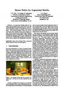
070124-002 such a way that it is meaningful to anyone, not just trained personnel. It is also of great importance that errors can be seen and reacted to quickly, especially in regards to hardware-inthe-loop testing and real world operations. In summary, this paper proposes a novel framework for rapid evaluation and integration of embedded technologies for AUVs. Mixed reality techniques are used to provide, and display, more feedback information to the operator, or developer, and thus improve their situational awareness. This can be achieved in simulation, real world testing or a hybrid of the two. The speed that errors are detected is therefore greatly increased and a more accurate system can be developed in a smaller amount of time. The framework provides the required functionality by incorporating a set of visualisation tools, communication protocols and vehicle dynamics models. Most importantly, it provides high-fidelity simulation of real platforms and sensors which can be used in mixed reality systems e.g. in hybrid simulation [5, 7] (both real and virtual sensors working together). The sensor simulation is provided by the Augmented Reality Framework (ARF) which uses a 3D virtual reality environment to display data, provide operator control and simulate exterioceptive sensors for use with mixed reality testing such as HIL. ARF provides the missing element which will provide the enhanced situational awareness required. ARF uses the same communication protocol and thus allows for the seamless substitution of real for virtual sensors. The rest of this paper is dedicated to explaining the various parts of the framework, how they interact and examples of current and future usages and their benefits. Firstly, the concepts Augmented Reality and Mixed Reality testing are discussed. II. HARDWARE-IN-THE-LOOP CONCEPTS Ronald T. Azuma [2] describes the idea of Milgrim’s Reality-Virtuality continuum [4]. His description shows the continuum from reality to virtual reality and all the hybrid stages in between. The stages between virtual and real are mixed reality types such as augmented reality [3] and augmented virtuality [3] (see figure 1). The hybrid reality concepts are built upon by the ideas of HIL and Hybrid Simulation (HS). The proposed framework is able to provide functionality across all stages of the continuum allowing for virtually any testing scenario to be realised. For this reason it is referred to as a mixed reality framework. There are current 4 different testing scenarios: 1. Simulation [5] - individual testing of each module before integration onto the intended platform. 2. Hardware-in-the-loop [6] (HIL) - where testing of the real integrated platform is carried out in a laboratory environment. However, exterioceptive sensors (e.g. sonar, video), which interact with the intended environment, may have to be simulated to fool the robot into thinking it is somewhere that it is not. Thus, this is very useful for integration testing as the entire system can be tested as a whole allowing for any system integration errors to be detected in advance of real world trials.
2 3.
Hybrid Simulation [5, 7] (HS) - This involves testing the platform in its intended environment in conjunction with some simulated sensors driven from a virtual world. For example, virtual objects can be added to the real world and the exterioceptive sensor data altered so that the robot thinks that something in the sensor dataset is real. This type of system is used if some higher level modules are not yet reliable enough to do what they intended to do. Consequently, fictitious data is used instead, or augmented with current data, as inputs to these systems. This is so that if a mistake is made it doesn’t damage the platform. An example of this would be obstacle avoidance system testing on an AUV (see example in section VIII). 4. Real world testing - This is the last stage of testing. When all systems are trusted then the platform can be tested its intended environment. Therefore, all implementation errors should have been fixed in the previous stages otherwise this stage is very costly. The next Section gives examples of how each type of testing corresponds to a different type of reality. III. REALITY TYPES AND TESTING The different types of testing correspond to different stages of the reality continuum. See figure 1. Real world Testing
Physical Reality (Remote Environ-
Hybrid Simulation
Augmented Reality (AR)
HIL Testing
Augmented Virtuality (AV)
Simulated Tests
Virtual Reality (Virtual Environment)
Figure 1: Reality Continuum combined with Testing scenarios.
Augmented Reality (AR) and Augmented Virtuality (AV) refer to how the reality or virtual reality is altered respectively. Augmented Reality is where simulated data is added to the real world perception of some entity. For example sonar data on an AUV could be altered so that it contains fictitious objects i.e. objects which are not present in the real world. For example, this could be used to test the higher level systems of an AUV such as obstacle detection (See Obstacle detection and avoidance example in Section VIII). In order to do this, a virtual world is used to generate synthetic sensor data, however, it needs to be kept in exact synchronization with the real world. The problem of synchronising the position of the virtual world to the real world is known as a registration problem. The accuracy of registration is dependent on the accuracy of the position/navigation systems. Registration is a well known problem with underwater vehicles when trying to match different sensor datasets to one another for visualisation. Accurate registration is paramount to displaying the virtual objects in the correct position in the simulated sensor data. Augmented virtuality is the opposite of augmented reality i.e. instead of being from a person’s perspective it is from the virtual world’s perspective i.e. the virtual world is augmented
070124-002 IV. FRAMEWORK COMMUNICATIONS PROTOCOL
Osh Manager
Osh Manager
The Obstacle detection and avoidance example (in section VIII) highlights the need for a distributed communication system. This system must allow for modules to be swapped, for similar simulated modules, without the other systems knowing, having to be informed or programmed to allow it. The underlying communication protocol which provides the flexibility needed by the framework is OceanSHELL[1]. OceanSHELL provides distributed communications allowing modules to run anywhere i.e. provides module location transparency. Location transparency makes mixed reality testing straight forward because modules can run either on the remote platform, or somewhere else such as a laboratory. OceanShell is a software library implementing a low overhead architecture for organising and communicating between distributed processes. OceanSHELL’s low overhead in terms of execution speed, size and complexity make it eminently suited for embedded applications. An extension to OceanShell called JavaShell is portable because it runs on Java [8] platforms. Both JavaShell and OceanShell fully interact, the only difference being that OceanShell uses C structures to specify message types instead of XML files which JavaShell uses. Thus OceanShell is not only platform independent but also language independent, making it fully portable.
Wireless Network Bridge
with real data. For example, real data collected by real sensors on an AUV is rendered in real time in the virtual world in order to recreate the real world in virtual reality. This can be used for Online Monitoring [5] (OM) and operator training [5] (TR) as the operator can see how the AUV is situated in the remote environment. From the perspective of testing, HS is where the platform operates in its intended environment but some sensors are simulated, in real-time, from a synchronized virtual environment. Similarly to AR, the virtual environment is kept in synchronization using position data transmitted from the remote platform. Thus simulated sensors are attached to the virtual reality version of the remote platform and moved around in synchronization with the real platform. Simulated sensors collect data from the virtual world and transmit the data back to the real systems on the remote platform. The remote platform systems then interpret this data as if it were real. It is important that simulated data is very similar to the real data so that the higher level systems cannot distinguish between the two. In summary, the real platform’s perception of the real environment is being augmented with virtual data. Hence HS is inherently Augmented Reality. An example of a real scenario where AR testing procedures are useful is in the case of obstacle detection and avoidance in the underwater environment by an AUV. See Obstacle detection and avoidance example in Section VIII. Hardware-in-the-Loop (HIL) is another type of Mixed Reality testing. The platform is not situated in its intended environment, but is instead fooled into thinking it is. This is achieved by simulating some exterioceptive sensors in a virtual environment. Virtual sensor data is then sent to the real platform’s systems in order to fool them. If possible the outputs of higher level systems, which rely on the simulated data, are also displayed in the virtual environment. This can help show the system developer that the robot is interpreting the simulated sensor data correctly. In HIL it is the sensors and systems which interact directly with the environment which are simulated. Vehicle navigation systems are a standard case as these use exterioceptive sensors, actuators and motors to determine position. Using simulated sensors means that the developer can specify exactly the data which will be fed into the systems being tested. This is complicated to do reliably in the real environment as there are too many external factors which cannot be controlled. Therefore, HIL is mixed reality since both virtual and real realities are being augmented with data. Thus HIL and HS are both deemed to be Mixed Reality concepts. The intended framework provides the ability to execute all testing regimes across the reality continuum. It does this by incorporating a distributed communication protocol, vehicle dynamics & navigation simulators, sensor simulation, an interactive three-dimensional (3d) virtual world and information display. All the different components are easily interconnected using message passing via the communication protocol. The key to the frameworks functionality is the flexibility of the communications protocol.
3
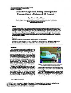
Figure 2: This diagram shows how OceanSHELL provides the backbone for switching between real and simulated (topside) components for use with HS/HIL.
OceanShell provides extra functionality for TCP/IP forwarding of UDP/OceanShell traffic across large networks. This is a software router which can be used to bridge OceanShell networks and filter the traffic. This technology is currently being researched in the Ocean Systems Laboratory and is called OshManager. OshManager also provides the ability to stop and start modules which implement the new OshManager interface. This means that real modules can be switched off when HS or HIL testing needs to be executed. This makes substitution of real and simulated modules straightforward which is useful for mixed reality testing. This allows the operator to choose which data they wish to forward from the remote environment to the virtual environment. This data can then be interpreted and displayed meaningfully to the operator. Section VI on ARF shows how data is forwarded and how it is interpreted for use with OM, HIL and HS. Figure 2 shows how OceanSHELL is used to communicate between the remote environment and the virtual environment.
070124-002 V. VISUALISATION, DATA FUSION AND OPERATOR AWARENESS. Aside from testing purposes virtual environments have many other uses. In the field of underwater exploration virtual environments become paramount when trying to relay what is happening to the operator(s).
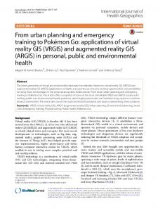
Figure 3: One of the framework visualisations showing current AUV position, where it has been, and a light marker indicating the next waypoint.
Augmented Virtuality environments are the most common implementation used to observe an AUV in its remote environment. Virtual environments have already been identified as an invaluable tool for online monitoring (OM) and operator training (TR). A virtual environment allows the operator to choose to see the robot from any position or angle (See figure 3). Therefore, the operator is able to see where the robot is in relation to everything else, and is therefore less likely to get confused about where the robot is and what it is doing. In the case of a remotely operated vehicle (ROV), the operator uses a 1st person video to see whether the ROV has responded appropriately. However, in the case of an AUV this is not available since the communication bandwidth is usually too small to relay responsive video footage. Quite often is the case, in underwater environments especially, that even if video is available it is not very informative because there is nothing to see due to low light levels and dirty water. Therefore, the operator cannot situate themselves easily just by looking at a video camera display. A virtual reality view of the underwater environment is therefore more informative. The virtual environment is kept synchronized by forwarding compact high level data types, across the communication medium. Such data can include proprioceptive sensor data (information about the vehicle state, e.g. position, velocity, hull temperature, water leak sensor etc) and exterioceptive sensor data (these measure information about the surrounding external environment, e.g. sonar, video, radar). Since communication bandwidth is limited it is very rare that raw information will ever be transmitted to the virtual environment. Instead, higher level interpretations made by the robots subsystems will be transmitted. For example, features identified in sonar or video data, and their associated positions, are transmitted instead. This information is then displayed in the virtual environment. Other information such as robot heading and current mission targets can also be displayed so that the operator can see what is happening e.g. a course change due to an identified object in the distance. This is achieved by the robot transmitting changes to its mission plans based on its observations of the remote environment.
4 These changes can then be displayed to the operator in 3D to show where the robot is next heading. An interactive visualisation, where the operator controls and sees the feedback from the AUV in real-time, provides a more realistic experience. If this is combined with HIL, by using a vehicle dynamics simulator and a real ROV, the operator can practise controlling the ROV, and running missions, before the ROV has even been in the water. Thus, making operator training quicker and less costly. In summary, the framework provides all the necessary tools for online monitoring and operator training. For online monitoring a visualisation capable of displaying the robots current position and other sensor data is required. For operator training, an additional vehicle dynamics simulator is required to simulate how the real vehicle moves in the real environment. The dynamics simulator is simply substituted for the real vehicle positioning systems. All the higher level systems such as vehicle control and autopilot simply use the navigation information from the dynamics simulator instead. The rest of the vehicle executes as normal in a HIL fashion with the vehicle dynamics simulator. In order to make the experience more realistic, further exterioceptive sensors can be simulated from the virtual environment, such as sonar and video, to replace the real systems. The framework has many components which provide the required functionality of OM, TR, HIL and HS. The main components being a location transparent communications protocol, a vehicle dynamics and navigation simulator, a 3D visualisation for observation only, and a more advanced mixed reality 3D virtual environment called ARF (Section VI for Augmented Reality Framework). VI. AUGMENTED REALITY FRAMEWORK (ARF) The Augmented Reality Framework (ARF) is a configurable and extendible virtual reality framework of tools for creating mixed reality environments. It provides sensor simulation, sensor data interpretation, visualisation and operator interaction with the remote platform. ARF can be extended to use many sensors and data interpreters specific to the needs of the user and target environment type. ARF is domain independent and can be tailored to the specific needs of the application. The ARF framework provides modularity and extendibility by providing mechanisms and programming libraries which allow a developer to create their own programmed components. The ARF framework provides a 3d virtual world which the components use to display information or simulate sensors. The framework provides many basic components to build virtual environments from. These components can then be configured specifically to work as desired by the user. If no such component exists the user can program their own and then add it to the ARF component library. For example, a component could be a sensor data listener which listens for certain data messages on some communication protocol (OceanSHELL), and then displays the data live in the virtual environment. The component may be literally an interface to a communications protocol like OceanSHELL, that from which other components connect to in order to listen and transmit data. Thus, the
070124-002
5
number of components will grow and so will the flexibility of the ARF. ARF also has the ability to link together and configure components. The linked component can then be exported as a super-component to the ARF component library for others to use. For example, an AUV a super-component could include: a 3D model of an AUV, a Vehicle Dynamics simulator, a sonar, and a control input to the Vehicle Dynamics (such as a keyboard or joystick). These virtual components can then be substituted for the real AUV systems for use with HIL and HS. ARF allows complete scenarios to be loaded and saved so that no work is required to recreate an environment. ARF has components which provide interfaces to OceanSHELL, sensor simulation (sonar and video) and provides components for interpreting live OceanSHELL traffic and displaying it meaningfully in the virtual world. In order to provide the HIL and HS capabilities, ARF provides a graphical interface to OshManager which allows the user to decide which type of OceanSHELL messages to forward to and from the robot. This also allows the user to choose which data to communicate to/from the virtual environment and remote platform. Thus, the framework uses ARF to provide both HIL and HS concurrently. Figure 6 shows an example of the ARF virtual environment. VII. FRAMEWORK STRUCTURE, This section gives an overview of how the different components configurations are used to implement different scenarios. OM and TR scenarios implementations are illustrated below. However, more detailed examples of HIL and HS are given in section VIII.
Figure 5: Operator Training Scenario
VIII. REAL WORLD APPLICATIONS & EXAMPLES Although the set of applications is innumerable, this section describes some representative examples of applications and topics of research that are already gaining benefits from the capabilities provided by the Augmented Reality Framework. A. Obstacle detection and avoidance One of the most common problems for unmanned vehicles is trajectory planning. This is the need to navigate in unknown environments, trying to reach a goal or target, while avoiding obstacles. These environments are expected to be in permanent change. As consequence, sensors are installed on the vehicle to continuously provide local information about these changes. When object detections or modifications are sensed, the platform is expected to be able to react in real time and continuously adapt the trajectory to the current mission targeted waypoint.
Figure 4: Online Monitoring Scenario
Figure 4 is a typical configuration for an operator wishing to observe an AUV’s mission progress. Figure 5 is more applicable to ROVs since they require a pilot to control them and therefore need controller input. The examples highlight how simple changes to component configuration provide completely different scenarios or test-bed set ups. For example, the OshManager needs reconfiguring to forward communications in both directions, and another control module needs to be added to the ARF virtual environment so that the operator can control the vehicle (ROV). The feedback of the ROV moving is then displayed in the virtual world for the operator to see. This is useful for operator training (TR). A further enhancement would be to simulate the vehicle navigation systems so that the operator is trained in a fully synthetic environment i.e. with the ROV in a HIL configuration.
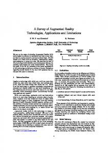
Figure 6: The ARF virtual environment simulating Forward-look sonar of virtual objects.
Testing these kinds of adaptive algorithms requires driving the vehicle against man-made structures in order to analyse its response behaviours. This incurs high collision risks on the platform and clearly compromises the vehicle’s survivability. A novel approach to this problem uses the described framework to remove the collision risk during the development process. Using Hybrid Simulation, the approach uses a set of simulated sensors for rendering synthetic acoustic images from virtually placed obstacles. The algorithms are then debugged on a real platform performing avoidance manoeuvres
070124-002 over the virtual obstacles in a real environment. Figure 2 shows the required framework components and Figure 6 shows the virtual environment view. It should be noted that the topside simulated components can be switched on to replace the remote platform’s real components, therefore achieving HIL or HS. A detailed description of the evaluation and testing of obstacle avoidance algorithms for AUVs can be found in [9] and [10]. B. Multi vehicle applications The main object of the European Project GREX[12] is to create a conceptual framework and middleware systems to coordinate a swarm of diverse, heterogeneous physical objects (underwater vehicles) working in cooperation to achieve a well defined practical goal (e.g. search of hydrothermal vents) in an optimised manner. In the context of GREX, algorithms for coordinated control are being developed. As these algorithms need to be tested in different vehicle platforms (and for different scenarios), testing in real life becomes difficult due to the cost of transporting vehicles; furthermore, the efficiency and safety of the different control strategies need to be tested. The virtual environment provides the ideal test bed: simulations can be run externally and fed into the virtual AUVs, so that the suitability of the different control strategies can be observed. C. Autonomous tracking for pipeline inspection Oil companies are raising interest in AUV technologies for improving large field oil availability and, therefore, production. It is known that Inspection, Repair and Maintenance (IRM) comprise up to 90% of the related field activity. This inspection is clearly dictated by the vessels availability. One analysis of potential cost savings is using an inspection AUV. The predicted savings of this over traditional methods for inspecting a pipeline network system are up to 30%. Planning and control vehicle payloads, such as the AUTOTRACKER payload [11], can provide such capabilities. However, as mentioned, vessel availability and off-shore operation costs make these types of payloads a difficult technology to evaluate. The described framework can provide simulated sidescan sonar sensors for synthetic generated pipeline rendering. These capabilities provide a transparent interface for the correct and low cost debug of the tracking technologies. D. Other applications 1) Simultaneous localisation and mapping Simulataneous localisation and mapping (SLAM) is done on simulated sonar from a virtual objects in the ARF virtual environment. Feature detection done on simulated sonar output. The systems tries to estimate the position of the AUV based upon the detected feature positions relative to the vehicle. 2) Computer aided detection and classification Simulated sidescan sonar is used instead of real sidescan for simulating mine detection and removal missions.
6 IX. RESULTS. CONCLUSIONS AND FURTHER WORK The proposed framework has already been harnessed to provide improved embedded systems development. This is achieved by more variety of testing scenarios and enhanced operator awareness. The task of designing framework components has been made simpler since all platforms in the Ocean Systems Laboratory have been developed using OceanSHELL. As a result, many higher level existing embedded components can be utilised both on and off the embedded system, meaning only exterioceptive sensors require simulation. The remaining areas requiring further research to provide the mixed reality framework includes: sensor simulation, interactive 3d environment for visualisation and control, and user control for substituting real for virtual components in realtime. These requirements are provided by the Augmented Reality Framework (ARF) and OshManager for OceanSHELL. The research into these areas is still in its infancy. However, the basic functionality has already been demonstrated in the real world applications discussed earlier. Further research is being carried out in the field of more accurate sensor simulation and component hierarchy for ARF to increase the functionality. Other components can be created using ARF or simply be standalone and use OceanSHELL to interact. REFERENCES [1]
‘Ocean-Shell: An embedded library for Distributed Applications and Communications’, Ocean Systems Laboratory, Heriot-Watt University [2] R Ronald T. Azuma. A survey of augmented reality. In Teleoperators and Virtual Environments 6, 4 Pages 355-385, August 1997. [3] Y.; Behringer R.; Feiner S.; Julier S.; MacIntyre B.; Azuma, R.; Baillot. Recent advances in augmented reality. Computer Graphics and Applications, IEEE, Volume 2, Issue 6:34 – 47, Nov.-Dec. 2001. [4] H. Takemura et al. Milgram, P. Augmented reality: A class of displays on the reality-virutality continuum. SPIE Proceedings: Telemanipulator and Telepresence Technologies . H. Das, SPIE. 2351 : 282-292, 1994. [5] E.; Ribas D.; Carreras M.; Ridao, P.; Batlle. Neptune: A HIL simulator for multiple UUVS. In OCEANS ’04. MTS/IEEE TECHNOOCEAN’04 Volume 1, 9-12 Nov. 2004 Page(s):524 - 531 Vol.1, 2004. [6] G.J.; Randall G.; Edwards I.; Lane, D.M.;Falconer. Interoperability and synchronisation of distributed hardware-in-the-loop simulation for underwater robot development: Issues and experiments. Amsterdam, Holland, 2001. Robotics and Automation, 2001. Proceedings 2001 ICRA. IEEE International Conference on Volume 1, 2001 Page(s):909 - 914 vol.1. [7] J. Choi, S.K.; Yuh. A virtual collaborative world simulator for underwater robots using multidimensional, synthetic environment. In Robotics and Automation, 2001. Proceedings 2001 ICRA. IEEE International Conference on Volume 1, 2001 Page(s):926 - 931 vol.1, 2001. [8] Java http://www.java.com. [9] C. Pêtrès and Y. Pailhas and P. Patrón and Y. Petillot and J. Evans and D. M. Lane; Path Planning for Autonomous Underwater Vehicles; IEEE Transactions on Robotics, April, 2007 [10] P. Patrón, B. Smith, Y. Pailhas, C. Capus and J. Evans; Strategies and Sensors Technologies for UUV Collision, Obstacle Avoidance and Escape; 7th Unmanned Underwater Vehicle Showcase; September 2005 [11] P. Patrón, J. Evans, J. Brydon and J. Jamieson; AUTOTRACKER: Autonomous pipeline inspection: Sea Trials 2005; World Maritime Technology Conference - Advances in Technology for Underwater Vehicles; March 2006 [12] http://www.grex-project.eu/