PHYSICS OF FLUIDS 22, 043601 共2010兲
Nonlinear spacing and frequency effects of an oscillating cylinder in the wake of a stationary cylinder Xiaofan Yang and Zhongquan Charlie Zhenga兲 Department of Mechanical and Nuclear Engineering, Kansas State University, Manhattan, Kansas 66506, USA
共Received 25 November 2009; accepted 16 February 2010; published online 7 April 2010兲
rs on al
co py
Nonlinear responses to a transversely oscillating cylinder in the wake of a stationary upstream cylinder are studied theoretically by using an immersed-boundary method at Re= 100. Response states are investigated in the three flow regimes for a tandem-cylinder system: the “vortex suppression” regime, the critical spacing regime, and the “vortex formation” regime. When the downstream cylinder is forced to oscillate at a fixed frequency and amplitude, the response state of flow around the two cylinders varies with different spacing between the two cylinders, while in the same flow regime, the response state can change with the oscillating frequency and amplitude of the downstream cylinder. Based on velocity phase portraits, each of the nonlinear response states can be categorized into one of the three states in the order of increasing chaotic levels: lock-in, transitional, or quasiperiodic. These states can also be correlated with velocity spectral behaviors. The discussions are conducted using near-wake velocity phase portraits, spectral analyses, and related vorticity fields. A general trend in the bifurcation diagrams of frequency spacing shows the smaller the spacing, frequency, or amplitude, the less chaotic the response state of the system and more likely the downstream and upstream wakes are in the same response state. The system is not locked-in in any case when the spacing between the cylinders is larger than the critical spacing. The near-wake velocity spectral behaviors correspond to the nonlinear response states, with narrow-banded peaks shown at the oscillation frequency and its harmonics in the lock-in cases. High frequency harmonic peaks, caused by interactions between the upstream wake and the downstream oscillating cylinder, are reduced in the near-wake velocity spectra of the upstream cylinder when the spacing increases. © 2010 American Institute of Physics. 关doi:10.1063/1.3372169兴
pe
I. INTRODUCTION
au
th
or
's
Wake-structure interactions among oscillating tandem cylinders can be found in many engineering applications, such as arrays of tubes in heat exchangers, power lines, and off-shore engineering structures. It is a complicated problem because the behavior of this nonlinear system depends on a combination of parameters related to both oscillating motions and tandem arrangement. This creates many nonlinear physical phenomena that are of interest to those who research fluid dynamics. The purpose of this study was to investigate how spacing and frequency influence the nonlinear behaviors of flow around the two cylinders when the downstream cylinder oscillates transversely. This study extends the current findings in the literature.1–3 Papaioannou et al.1 investigated the holes in the Arnold tongues of flow past two oscillating cylinders that oscillate simultaneously at the same amplitude and frequency. Karniadakis and Triantafyllou2 and Zheng and Zhang3 studied the nonlinear and frequency lock-in behaviors of a single oscillating cylinder for different frequencies and amplitudes. Historically, a simpler version of the problem—the response of a single circular cylinder oscillating in a uniform stream—has been studied extensively using experimental a兲
Electronic mail:
[email protected].
1070-6631/2010/22共4兲/043601/15/$30.00
measurements and numerical simulations.4–6 Detailed mechanisms of this problem have also been reviewed.7 Furthermore, a new development in the numerical schemes for computational studies of flow over a two-dimensional oscillating cylinder has been recently reported.2,3,8,9 In these studies, almost every aspect in the single cylinder with/without external forcing—from vortex formation 共VF兲 and wake structures to frequency selection and response states—has been investigated thoroughly. The literature concerning flow over two stationary tandem cylinders includes experimental observations7,10,11 and numerical simulations.12–15 Physical mechanisms involved in two tandem cylinders are very different from those in a single cylinder because the wakes that are shed from both cylinders are coupled and interact with each other. The vorticity field is significantly affected by the Reynolds number 共Re= UD / 兲 and the spacing between the two cylinders. As confirmed in the literature13 and this study, the Strouhal number 共St= fD / U兲 of the two tandem cylinders is not the same as that of the single cylinder for the same Reynolds number. In addition, the Strouhal number is identical for both of the cylinders in the system. Compared with single stationary cylinder cases, which are mostly dominated by Reynolds numbers, the spacing effect of the tandem cylinders is another important factor. It has been found that by changing the distance between the two cylinders wake formation and coupling may vary. Most interestingly, there exists a critical
22, 043601-1
© 2010 American Institute of Physics
Phys. Fluids 22, 043601 共2010兲
X. Yang and Z. C. Zheng
∂u/∂y = 0 v = 0
0.8D
0.8D
0.8D
u = U∝ v=0
pe
's
or
th
au
∂u/∂x = 0 ∂v/∂x = 0
25.6
P2
P1 U∝
0.8D
S
8 y
∂u/∂y = 0 v = 0
x
38.4
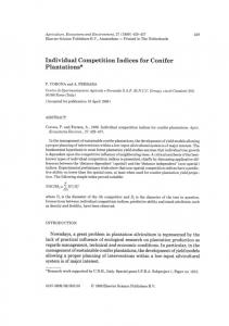
FIG. 1. Computational domain, boundary conditions, and near-wake velocity probing points.
A detailed discussion on the oscillating downstream cylinder cases is presented in Sec. IV, and the conclusions are made in Sec. V. II. NUMERICAL SIMULATION
Direct numerical simulations based on an improved IBM with direct forcing24 are carried out to simulate the flow system. The nondimensionalized governing equations using the characteristic parameters of , U, and D for twodimensional, laminar, incompressible flow are
rs on al
spacing distance 共Sc兲 on the border of the VF and vortex suppression 共VS兲 regimes, which is marked by a sudden jump and discontinuity of the Strouhal number. For low Reynolds number laminar cases 共in the range of 100 s兲, the critical spacing is predicted by Li et al.12 to be between 3 and 4 and by Sharman et al.13 to be between 3.75 and 4. The literature concerning oscillating cylinders in the tandem arrangement is relatively scarce. Li et al.16 studied numerically an oscillating cylinder in uniform flow and in the wake of an upstream stationary cylinder using a finiteelement method. They mimicked the oscillation effect of the downstream cylinder by defining a sinusoidal velocity on its surface without moving the second cylinder, so that a fixed grid mesh could be used. The investigation of oscillating tandem cylinder cases was focused on only one spacing in the VF regime in that study. More recently, Papaioannou et al.1 investigated the holes in the Arnold tongues of flow past two oscillating cylinders following the experimental evidence observed by Mahir and Rockwell.17 The Arnold tongue indicates the lock-in regions in the amplitude versus frequency diagrams. It was first proven to exist in the experiment by Ongoren and Rockwell.18 They studied the response states of a closely spaced tandem oscillating cylinders over a certain range of external forcing frequencies. The lock-in region was found to be wider than that of a single cylinder. Similar results were shown by Papaioannou et al.1 using numerical simulations. At Re= 160, they placed two cylinders near each other and oscillated under the same amplitude and frequency with either the same or opposite phase, and the shape of the Arnold tongue was clearly shown in their study. Several types of nonlinearity appeared in the velocity phase portrait, from lock-in, quasiperiodic, and transitional to period doubling. They also studied two spacing distances 共2.5 and 3.5兲 that could be related to the critical and VF regimes correspondingly, with a restriction of both of the cylinders oscillating at the same amplitude and frequency. The spacing and frequency effects on nonlinear behavior of a tandem cylinder system with two cylinders are therefore the focus of the current study that includes all of the three regimes of VS, critical, and VF regimes. It should also be noted that because the two cylinders in the current study are not in the same oscillating motion, many aspects of flow are different from those in Papaioannou et al.1 A primary difference is that the flow field behind the first cylinder can be very different from that behind the second cylinder in both frequency response and phase portrait. We found new vortex structures in the wake related to different nonlinear response states. While the response of a tandem cylinder system to a controlled oscillating downstream cylinder with a prescribed frequency is studied in the paper, there are many practical applications on flow around self-oscillating cylinders due to vortex-induced vibration.19–21 However, under certain conditions, some of the flow behaviors in controlled vibration can be very close to those in free vibration.22,23 The numerical scheme of the immersed-boundary method 共IBM兲 is explained in Sec. II. In Sec. III, the flow patterns of a system of two stationary cylinders at different spacing and the related Strouhal number effect are described.
co py
043601-2
ⵜ·u=0
共1兲
1 2 u ⵜ u + f, + u · ⵜu = − ⵜP + Re t
共2兲
and
where Re is defined as UD / , with U the uniform incoming velocity, D the cylinder diameter, and the kinematic viscosity. A Re of 100 is used for this study. The boundary forcing term f is applied on an internal layer of the immersed boundary and calculated at each time step to obtain the desired boundary velocity by using the formula f = S + ⵜP −
1 2 1 ⵜ u + 共v − u兲, Re ⌬t
共3兲
where v is the desired velocity and S is the convection term defined as S = 共u · ⵜ兲u. The internal layer is a layer of grid points that are immediately interior to each of the cylinder surface boundaries. The momentum equation, Eq. 共2兲, is solved using a second-order differencing scheme on a staggered Cartesian grid, which includes a semi-implicit scheme for the diffusion term 共with the normal direction diffusion terms being the Crank–Nicholson scheme兲, the Adams–Bashforth scheme for the convection, and second-order central differencing for diffusion. The incompressibility condition, Eq. 共1兲, is satisfied by solving a Poisson equation for pressure correction using FISHPACK. The overall accuracy of the scheme is able to reach the second order. More details concerning the modified IBM can be found in Zhang and Zheng.24 When the IBM is used, arbitrary shapes and motions of solid bodies can be effectively simulated by a proper construction of the boundary forcing term so that a simple, nonmoving Cartesian grid can be used. The domain size selected for this study is 38.4⫻ 25.6, as shown in Fig. 1. The up-
Phys. Fluids 22, 043601 共2010兲
Nonlinear spacing and frequency effects
stream cylinder is located at 8, sufficiently away from the inlet boundary to eliminate the inlet effect. The distance between the two cylinders is defined as S 共nondimensionalized by the cylinder diameter D兲. The outlet boundary is also far enough from the downstream cylinder to allow the vortex street to develop fully. The grid-size independence check24 determined that a grid size with ⌬x = ⌬y = 0.025 provides an acceptable grid resolution for all the computational cases at Re= 100. The boundary conditions are also shown in Fig. 1. For a stationary cylinder, the velocity on the surface is zero. For a transversely oscillating cylinder, the displacement is calculated as dy = A sin共2t ⴱ f c兲,
(a)
共4兲
(b)
au
th
or
's
pe
rs on al
where A 共nondimensionalized by D兲 is the amplitude of the displacement, f c is the forcing frequency, and t is the time. The time step size is computed from different forcing frequencies as ␦t = 1 / f cN, where N is the number of time steps within one oscillation period. Moreover, the size of the time step must also satisfy the stability criterion of an explicit scheme for a two-dimensional convection-diffusion equation, that is, ␦t ⬍ min关h2 Re/ 4 , 2 / 共u2 + v2兲Re兴, where h is the grid size. The computational scheme has been verified with numerous experimental and computational data.24 For example, for flow over a single oscillating cylinder, the computational results at various forcing frequencies were shown in Zheng and Zhang,3 where both frequency lock-in and non-lock-in cases were identified using time histories and power spectra of lift and drag, and good agreements were achieved in comparison to literature data.5,6,9,18 These examples have provided sufficient validations for the computational scheme used in our study. In order to justify the two-dimensional flow assumption in this study, we have tested three-dimensional simulation at Re= 100 with a periodic boundary condition in the cylinder axial direction. By examining the vorticity contours and velocity field in several cutting planes perpendicular to the cylinder axial direction, we have found that the flow remains two dimensional, with the variation range of these variables less than 1% along the axial direction. We also increased Reynolds number to 160, which is a case that was treated as two-dimensional tandem cylinders,1,15 and the three dimensionality started to show. Oscillation of the downstream cylinder does not enhance the three-dimensional effect much. Therefore, it is expected that the Reynolds number for flow to become three dimensional could be lower in a tandem cylinder system than that in a single cylinder system 关where Re= 188.5 共Ref. 25兲兴, with a possibility that oscillation could further reduce that Reynolds number. Considering the stabilizing and destabilizing effects of the downstream cylinder,15 this Reynolds number may also vary with the separation distance between the two cylinders. Although for the purpose of this study we do not intend to determine this Reynolds number, based on our simulation this Reynolds number can possibly be below 160. Also, the case we study here at Re= 100 is still within a safe range for flow to be two dimensional, hence formation due to instability in the axial direction is not considered.26
co py
043601-3
(c)
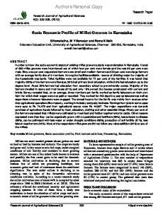
FIG. 2. 共Color online兲 Vorticity field for a stationary tandem cylinder system at three different spacing distances: 共a兲 S = 2 共VS兲, 共b兲 S = 4 共critical兲, and 共c兲 S = 6 共VF兲.
III. FLOW PATTERNS FOR FLOW OVER TWO STATIONARY TANDEM CYLINDERS
Complicated flow patterns in a stationary tandem cylinder system have been demonstrated in the literature.7,10,11,13 Basically, the flow patterns can be divided into two regimes by a “critical spacing” 共Sc兲. In the case of Re= 100, the value of Sc is between 3.75 and 4, according to Sharman et al.13 The different types of vortex streets are shown in the vorticity contours for Re= 100 in Fig. 2. When S ⬍ Sc 共S = 2 in Fig. 2兲, the flow is in a regime called the “VS regime,” in which the wakes behind both cylinders are rather weak, and there is almost no vortex shedding, neither in between nor behind the cylinders other than a low-frequency wavy flow pattern in the wake. The downstream cylinder is so close to the upstream one that formation of vortices is hindered. The shear layer from the upstream cylinder does not have sufficient room to form shed vortices, although there is no precise relation between the VF length in the wake of a single cylinder and the critical spacing of a tandem cylinder system.15 The stabilized wake behind the upstream cylinder 共in the sense of a Hopf bifurcation25兲, due to the closeness of the downstream cylinder, further stabilizes the wake from the second cylinder so that there is no clear vortex shedding even in the wake
Phys. Fluids 22, 043601 共2010兲
X. Yang and Z. C. Zheng Papaioannou et al 2006b, Re = 160 current scheme, Re = 160 Li et al, 1991, Re = 100 Sharman et al, 2005, Re = 100 current scheme, Re = 100 current scheme, Re = 80
0.2
Strouhal number (St)
0.18
0.16
0.14
0.12
0.1
1
2
3
4
5
6
7
8
Spacing (S) FIG. 3. 共Color online兲 Comparisons of Strouhal number prediction for a stationary tandem cylinder system at different spacing distances 共S兲 and Reynolds numbers of 80, 100, and 160.
IV. SPACING AND FREQUENCY EFFECTS OF A TRANSVERSELY OSCILLATING DOWNSTREAM CYLINDER
au
th
or
's
pe
rs on al
after the downstream cylinder. When approaching the critical spacing, the vortex shedding upstream to the second cylinder is intermittent. After a transient period, at S = Sc 共S = 4 in Fig. 2兲, a synchronized vortex street is formed eventually behind the downstream cylinder, and a sudden jump in the Strouhal number 共St= fD / U兲 for the cylinder system occurs, although there is still no clear vortex shedding between the cylinders. It should be noted that this Strouhal number is for the entire tandem cylinder system and includes interference effects among the two cylinders and their wakes, which is not the same as that for a single cylinder. This sudden jump is indicative that the spacing is reaching the critical spacing. When S ⬎ Sc 共S = 6 in Fig. 2兲, the flow is in the “VF regime,” in which synchronized vortex shedding occurs and well developed vortices are shed from the upstream cylinder and reattach themselves to the downstream one. The shedding vortices behind the first cylinder join those from the downstream cylinder to form a coupled vortex street in the wake of the tandem cylinder system. Figure 3 shows the computed Strouhal number versus the spacing distance at Re= 100 and two other Reynolds numbers at 80 and 160 for comparison. The reason to end at Re= 160 is because of three dimensionality at high Reynolds number flow stated in Sec. II. On the other hand, at further lower Reynolds numbers, such as Re= 50 as we tested, the flow is at the verge of being a steady state with a long wake formation length for a single cylinder case. The possible stabilizing effect of the downstream cylinder can make the flow even more stable, and therefore the VF regime is large and no vortex shedding is shown in this regime. In our computation, the Strouhal number is calculated after the periodic vortex streets are formed and the solution converges to a state that shows periodic oscillations. The average surface pressure coefficient history, during the periods after a converged solution 共80 or 160 depending on the frequency resolution needed兲 is established, is then used for spectral
analysis to determine the Strouhal number. Our St values at Re= 100 fit between those reported by Sharman et al.13 and Li et al.12 The sudden jump of the Strouhal number occurs at S = 4 in all of the three data sets. For another Reynolds number of 80, we also repeated the same procedure and obtained the critical spacing around 5.5, as shown in Fig. 3, which agrees well with the result by Tanida et al.,11 but is different from the value of 3.7 reported by Li et al.16 One of the reasons could be the resolutions of the grid mesh. As for the single cylinder case with Re= 100, a relatively coarse mesh was used by Li et al.16 that gave the value of St as 0.166, a bit lower than the usual value of 0.17 reported in the literature. Another reason could be due to different definitions of the critical spacing. There are several different ways of determining the critical spacing in the literature. We define the critical spacing by observing the sudden increase in the Strouhal number, which is the same definition as what used by Sharman et al.13 In Li et al.16 the wake length change as an indicator of separate flow regimes was used, while in Tanida et al.11 the interference drag was used as the criterion.
co py
043601-4
Oscillations of the downstream cylinder create more complicated nonlinear behaviors and add two more parameters to the stationary tandem cylinder system: the frequency and the amplitude of the oscillating downstream cylinder. In this study, we investigated different oscillating frequencies at various spacings under relatively small amplitudes. It should be noted that oscillations of cylinder do not alter the spacing range significantly in distinguishing the VS and VF regimes, as long as the oscillation amplitude is small such as those in this study. In terms of phase portrait of velocity field, in a stationary tandem cylinder system there is always a “lock-in” type in the phase portrait of both downstream and upstream wakes, since there is only one major characteristic frequency in the system corresponding to the Strouhal number of the stationary tandem system. In the following discussions, we analyze nonlinear behaviors for each case 共at a specific spacing, frequency, and amplitude兲 in three ways: 共1兲 phase portrait plots to analyze the nonlinear dynamic mechanism; 共2兲 power spectral analyses to reveal frequency effects; and 共3兲 vorticity contour plots to explain the flow physics and vortex patterns. Velocity histories are recorded at two points that are both 0.8D downstream of the center of each cylinder and 0.8D above the center line in the transverse direction 共P1 and P2 shown in Fig. 1兲. These points are in the near-wake region and thus the effects from vortex shedding and oscillations of the cylinder can be easily detected. For P1, we can detect the behaviors in the wake of the upstream cylinder, while for P2, the merging effect of the vortex streets of the two cylinders can be seen. Power spectral analyses are carried out using the histories of streamwise velocity in the last several periods. The dominant frequencies in the spectra can be used as one of the indicators for classifying the nonlinear response states. In the phase portrait plots, the trajectories of time histories of
Phys. Fluids 22, 043601 共2010兲
Nonlinear spacing and frequency effects 1.8 1.7
Frequency (fc/fns)
1.6 1.5 1.4 1.3 1.2 1.1 1 0.9 0.8
1
2
3
(a)
4
5
6
7
5
6
7
Spacing (S)
1.7 1.6 1.5 1.4
co py
1.8
1.3 1.2 1.1 1
0.9 0.8
(b)
1
2
3
4
Spacing (S)
FIG. 4. Response state diagrams of spacing vs frequency for probed velocities in the wake of each of the cylinders at A = 0.15. 共a兲 Upstream cylinder; 共b兲 downstream cylinder. Triangle: lock-in; square: transitional; circle: quasiperiodic. The filled symbols indicate that wake velocity spectra of the upstream cylinder lose peaks at high frequencies.
au
th
or
's
pe
rs on al
the streamwise 共u兲 and the transverse 共v兲 velocity components are mapped into the u-v plane to identify the limit cycles for characterizing responses of the nonlinear system under forcing. For the problems of flow over cylinders, phase portraits of velocity have been used to categorize nonlinear response states.1,2,16 In this study, the spacing between the two cylinders is considered a major factor that influences system behaviors, which differs from a previous study1 where frequency and amplitude were the main factors. At one oscillating frequency, under different spacing distances, the resulting flow patterns change. On the other hand, how the flow patterns vary with the oscillating frequencies is also highly influenced by the spacing distance between the two cylinders. Here we study three spacing distances of S = 2, 4, and 6, which correspond to the VS, critical, and VF flow regimes in the stationary tandem cylinder case, as discussed in Sec. III. For each of the spacing S, six different oscillating frequencies were tested: natural vortex shedding frequency 共f ns兲, two nearby frequencies 共f c = 0.9f ns , 1.1f ns兲, and three higher-frequency excitations 共f c = 1.3f ns , 1.5f ns , 1.7f ns兲. The oscillating displacement amplitude A was fixed at two relatively small values of 0.15 and 0.35. It should be noted that the natural frequency here, f ns, is the same as the Strouhal number of the corresponding stationary tandem cylinder system, a term also used in the literature.1 In this study, the intention is to investigate the response of the system to oscillations in the vicinity of this frequency. Therefore, the oscillation frequency f c is scaled by the natural frequency.1 This natural frequency changes with the spacing between the two cylinders, as shown in Fig. 3, because the system characteristics change. In this discussion, we first give an overall picture of the nonlinear behaviors of the system by showing bifurcation diagrams of normalized frequency 共with respect to the corresponding natural frequency兲 versus spacing in Figs. 4 and 5, drawn from the cases of different combinations of above mentioned parameters. The diagrams categorize all the cases into three states or classes: lock-in, transitional, and quasiperiodic, the same three classes used by Papaioannou et al.1 However, unlike the study by Papaioannou et al.1 in which the cylinders have the same motion 共although either perfectly in phase or in opposite phase兲, we have one forced oscillating cylinder and one stationary cylinder. We also distinguish, with filled or hollow symbols, whether there are peaks at high frequencies in the velocity spectra detected in the wake behind the upstream cylinder, a feature that is shown in the streamwise velocity spectra in Figs. 6 and 7 and will be further discussed in Secs. IV A–IV C. In addition, we inspect both the velocities behind the upstream cylinder 共at P1兲 and the downstream cylinder 共at P2兲 because flow in the downstream wake may not necessarily behave the same way as it does in the upstream wake. According to the results to be discussed later, the flow patterns in the two wakes can belong to different categories among the three states. Even when flows at P1 and P2 are in the same state, differences in spectra still exist. It is physically plausible that the upstream and downstream flows can be in the same class because of the incompressible, elliptic-type domain of influence, particu-
Frequency (fc/fns)
043601-5
larly when the spacing distance between the two cylinders is small. However, differences in flow features also exist due to different wakes behind the upstream cylinder with respect to each of the flow regimes. Particularly, if the distance between the two cylinders is sufficiently large, the differences are more likely to occur. The general trend illustrated in the diagrams shows that the smaller the spacing, frequency, and amplitude, the more likely the system is locked-in, and thus the bifurcation diagrams of frequency spacing do not form Arnold tongues. By comparing Fig. 4共a兲 with Fig. 4共b兲 and Fig. 5共a兲 with Fig. 5共b兲, we see that it is more likely that the upstream wake and downstream wake are in the same flow pattern class when the spacing is smaller and excitation frequency is lower. In addition, no high-frequency peaks appear in the upstream wake in the non-lock-in cases at the critical spacing and in all cases at the VF spacing. As long as the flow state is a lock-in, the upstream high-frequency peaks remain. The high-frequency peaks in the downstream wake are generated by interactions between the upstream wake and the oscillat-
043601-6
Phys. Fluids 22, 043601 共2010兲
X. Yang and Z. C. Zheng
1.8 1.7
Frequency (fc/fns)
1.6 1.5 1.4 1.3 1.2 1.1 1 0.9 0.8
1
2
3
(a)
4
5
6
7
Spacing (S)
1.8
co py
1.7 1.6 1.5
A. The VS spacing, S = 2
1.4
At the VS spacing 共S = 2兲, the two cylinders are in a very close arrangement. Unless the amplitude is sufficiently high, the existence of the downstream cylinder hinders the development of vortex shedding in the wake of the upstream cylinder. The wake of the upstream cylinder is “forced” to oscillate with that of the downstream cylinder, resulting in the same response between the two wakes. Furthermore, as flow oscillations in the VS cases are closely coupled between the upstream and downstream regions, the flow is locked-in in a wide frequency range, and flow patterns behind the two cylinders fall into the same flow class. The entire tandem cylinder system is thus similar to a single bluff body under oscillatory excitations. In the frequency-spacing diagrams in Figs. 4 and 5, at 0.9f ns to 1.3f ns, pure lock-in responses exist, which break down to quasiperiodic states at higher frequencies. The two different amplitudes result in the same type of responses, and increasing the amplitude further may break down lock-in at a lower frequency. When flow is locked in, significant peaks appear at the excitation frequency and its superharmonics. For example, in the case of f c = 1.3f ns, one dominant peak appears at 1.3f ns in the wake behind each cylinder, as shown in Figs. 6 and 7. There are no peaks at either f ns or its superharmonics. A limit cycle of a single closed orbit in Figs. 8共a兲 and 8共b兲 is repeated in time in the velocity phase portrait plots for both upstream and downstream wakes, indicating a pure lock-in for flow around both cylinders. Note that the numbers on both the abscissa and ordinate of all the phase portraits in this paper are in the unit of dimensionless velocity. Since this system behaves similarly to a single oscillating bluff body, vorticity contours in Fig. 8共c兲 show a typical 2S vortex shedding structure 共Ref. 5兲, in which each positive vortex is followed by a negative vortex behind the downstream cylinder. This vortex shedding pattern was also observed3 for single oscillating cylinder cases in the lock-in regime. For frequencies higher than 1.3f ns, the excitation frequency f c is away from the natural frequency f ns. The re-
1.3
rs on al
Frequency (fc/fns)
in the same general trend as in the above descriptions for Re= 100. Upon further inspection of the detailed frequency response behaviors at each spacing distance, we find that the spectral contents of near-field velocity histories, Figs. 6 and 7, can also be linked to the three states as 共1兲 for lock-in, there is a clear, narrow-banded dominant peak at f c and its harmonics; 共2兲 for transitional, there is a major, relatively broadband peak close to f c or f ns, and other peaks are in a scattered and insignificant manner; and 共3兲 for quasiperiodic, there are peaks at both f c and f ns, and also peaks at their respective harmonics. In Secs. IV A–IV C, we look into the frequency response behaviors presented in power spectrum plots at each spacing distance along with the phase portrait plots to confirm the compatibility among them in terms of classifying the response states. Furthermore, corresponding vortex shedding patterns in vorticity contour plots are also discussed in the context of response states.
1.2 1.1 1
0.8
(b)
1
2
3
4
5
Spacing (S)
pe
0.9 6
7
or
's
FIG. 5. Same as in Fig. 4 but with A = 0.35.
au
th
ing downstream cylinder. This explains why the highfrequency peaks no longer exist in the upstream wake at some critical and all VF spacing, because such interactions only weakly affect the upstream wake when the spacing is large. At the VS spacing, as the two cylinders are very close, the oscillatory flow effect due to the oscillating downstream cylinder is very strong, leading to high-frequency peaks in all the VS 共S = 2兲 cases. At the VF spacing, high-frequency peaks disappear in the upstream wake in all of the cases, while at the critical spacing, only the two lock-in cases at the lower amplitude in Fig. 4 do not show this phenomenon. Changing amplitudes does not affect either the VS cases or the VF cases, but does affect significantly the critical spacing cases, resulting in no lock-in for all the critical spacing cases at the larger amplitude. Therefore, critical spacing 共S = 4兲 is sensitive to excitation amplitude, which leads lock-in and transitional cases at the lower amplitude to either transitional or quasiperiodic at the higher amplitude. In a large spacing system of VF 共S = 6兲 cases, the upstream wake remains transitional and the downstream wake remains quasiperiodic, regardless of the frequency or the amplitude of the excitation. We also studied the state bifurcation diagrams for a lower Reynolds number case at Re= 80 共in which case the critical spacing is at S = 5.5, as discussed in Sec. III兲, and they are all
Phys. Fluids 22, 043601 共2010兲
Nonlinear spacing and frequency effects S2 0.9fns u&d