AbstractâRecently, capacitor current ramp compensation, which features fastest transient response, has been proposed to stabilize V2 control with low ...
Auto-tuning and Self-calibration Techniques for V2 Control with Capacitor Current Ramp Compensation Using Lossless Capacitor Current Sensing Pei-Hsin Liu1, Yingyi Yan2, Fred C. Lee1, and Qiang Li1 1
2
Center for Power Electronics Systems Virginia Tech Blacksburg, VA 24061 USA
Linear Technology
Milpitas, CA, 95035 USA.
Abstract—Recently, capacitor current ramp compensation, which features fastest transient response, has been proposed to stabilize V2 control with low equivalent-series-resistance (ESR) capacitor. However, it is found that the design of capacitor current sensing gain and the time-constant mismatch of sensing network may lead to oscillatory or slow transient response, so both issues are investigated in this paper to improve the control scheme. Firstly, the small signal model based on describing function is derived to identify the effect of capacitor current sensing gain on the system stability and transient performance. Secondly, based on the knowledge from this accurate model, a simple auto-tuning technique is developed to optimize the current sensing gain over possible parameter variations by detecting the transient response of output voltage. Thirdly, two easy self-calibration techniques are proposed to correct the time constant mismatch during output voltage scaling. Finally, the effectiveness of proposed methods is verified by SIMPLIS simulation and experimental results.
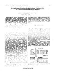
transient response [5]. Recently, the third method, capacitor current ramp compensation, was proposed [6]-[9]. To sense the capacitor current, a lossless R-C sensing network is in parallel with output capacitors, as shown in Fig. 1 [6]. When the time constant of current sensor branch (τCs=RCs*CCs) is designed to match the one of output capacitor (τCo=RCo*Co), the output of current sensor (VRCs) is proportional to actual capacitor current. With proper design, this method overcomes the drawback of the previous methods. It provides proper damping and maintains fastest transient than the first two methods due to the ultra-low output impedance.
I. INTRODUCTION The premium transient response of V2 controlled Buck converter is attractive for Point-of-load (PoL) converter application, but the V2 control with low ESR capacitor (such as ceramic capacitor) has instability issue [1]-[3]. To stabilize the V2 control with ceramic capacitor, there are several existing methods. The first method is adding inductor current ramp. It can stabilize the loop of constant on-time V2 control and provide a desired damping, but the output impedance of the converter becomes resistive which is equal to the current feedback gain, Ri. To null the DC output impedance, several commercial controllers such as TPS51518 of Texas Instrument insert a high pass filter in the current feedback path. However, the transient response turns out to be slower than V2 control with ESR-dominant capacitors, such as POSCAP and OSCON capacitors, because the high-pass filter introduces an additional lowfrequency pole on the output impedance [4]. The second method is adding external ramp, which may not be able to achieve proper damping for the control loop, especially in large duty cycle operation. A potential low-frequency high peaking of the output impedance can lead to an oscillatory
Figure 1 . V2 control with capacitor current ramp compensation [6]
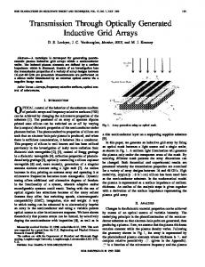
However, there are two challenging design concerns to be studied for this control scheme: The first design consideration is the selection of current signal amplification gain (Ks). It is critical, because it determines the damping of double pole at half of switching frequency in the system transfer functions, such as vo/vc and output impedance Zo. Fig. 2 shows the comparison of load transient responses in three different designs, where the Ks are 0.6, 10.9 and 285 respectively. It is illustrated that if the gain is too large, the over-damped double pole will slow down the transient response; if the gain is too small, the complex double pole will lead to an oscillatory response. This paper will identify the optimal design and propose an auto-tuning technique to search the appropriate Ks.
This work was support by Power Management Consortium (PMC) in Center of Power Electronics Systems (CPES), Virginia Tech
978-1-4799-5776-7/14/$31.00 ©2014 IEEE
1105
Figure 4
Simulated transient respon nse under -50% mismatch
Figure 2 . Load transient response in differentt Ks designs
The second challenge is matching thee time constant, because both component tolerance of CCs and Co with ceramic capacitor depend on DC biias, temperature characteristic of ceramic material, aging effect and manufacturing tolerance. When the time coonstant mismatch between the capacitor current sensing nnetwork and the output capacitor occurs, transient ressponse becomes oscillatory or slow due to peaking effect oof double pole at half of switching frequency on output impeedance. In Fig. 3, the simulated VRCs under ±50% of time coonstant mismatch shows that the strength of current feedbackk varies, and the current-slope distortion occurs. Even thoough the current amplification gain is properly design, thhe distortion of current signal can lead to an oscillatory ressponse, as shown in Fig. 4. Similarly, when τCs becomes 1.5 oof τCo, the double pole is over-damped, so the response beccomes slower. It means that over designing the sensing brannch time constant by making typical value of τCs longer than the typical value of τCo will further slowdown the transiennt response. This paper will propose a self-calibration technique to adjust the sensing branch time constant to match the ooutput capacitor.
SMALL-SIGNAL MODEL FOR V2 CONTROL WITH CAPACITOR CURRENT COMPENSATION O The nonlinear entity consists of switches, the output voltage, the comparator, and thee on-time generator. As shown in Fig. 5, a sinusoidal peerturbation with a small magnitude at the frequency is injeected through the control signal; then, based on the peerturbed output voltage waveform, the DF from the control signal to the output voltage can be found by mathematiccal derivation. II.
Figure 5
Modeling method of V2 con ntrol with capacitor current ramp compensattion
Figure 3 . Simulated VRCs under +/-50% time connstant mismatch
The rest of the paper is organized as follows. In order to study the Ks optimization, the small signal modeling for V2 control with capacitor current compenssation based on describing function will be presented in seection II. Section III proposes an auto-tuning technique off Ks. Section IV proposes two self-calibration technique too match the time constant. The simulation and experimental results verified the concepts in section V and section VI resspectively.
Figure 6
Pertrubed waveforms of V2 control with capacitor current ramp compen nsation
Following the modulation law w of constant on-time control, the duty cycle and the outpu ut voltage waveforms are shown in Fig. 6. Since the on-time (T ( on) is fixed, the off-time is modulated by the perturbation signal: vc (t ) = r0 + rˆ sin(2πf m ⋅ t + θ ) , wheree r0 is the steady-state dc value of the control signal, ̂ is the magnitude of the perturbation, fm is the perturbation frequency, and θ is the initial angle.
1106
Based on the modulation law, it is found that
vc (ti −1 + Toff ( i −1) ) + snTon − s f Toff ( i ) +
∫
ti +Toff ( i )
ti −1 +Toff ( i −1)
[iL (t ) − Co
vo (t ) ]dt RL (1)
half-plane according to different parameters of the capacitors. The critical condition for stability is RCo(1+Ks)Co>Ton/2, which clearly shows the influence of the capacitor current sensing gain.
= vc (ti + Toff ( i ) ) th
where Toff(i) is the i cycle off-time, Ls is the inductance of the inductor, Sn=(Vin-Vo)(1+Ks)RCo/Ls, Sf=Vo(1+Ks)RCo/Ls, RCo is the ESR of the output capacitors, Co is the capacitance of output capacitors, RL is the load resistor, iL(t) is the inductor current, and vo(t) is the output voltage. Based on (1), Toff(i) can be calculated. The perturbed duty cycle and the perturbed inductor current can be expressed. Then, Fourier analysis can be performed on the inductor current to derive the Fourier coefficient of inductor current cm(iL) at the perturbation frequency. Further, the Fourier coefficient of output voltage cm(vo) can be calculated. Therefore, the DF from the control signal to the output voltage can be calculated as cm ( vo )
RL ( RCo Co j 2π f m + 1) (2) ⋅ / (2 j ) ( RL + RCo )Co j 2π f m + 1
cm ( iL )
vo ( f m ) = − jθ = − jθ ˆ ˆ vc ( f m ) re / (2 j ) re
In the s-domain, the control-to-output transfer function can be expressed by: vo ( s ) = vc ( s )
1 ) RL Co s V RL ( RCoCo s + 1) ⋅ in Toff V T +T L s ( RL + RCo )Co ⋅ s + 1 ) − (1 − on sw )e− sTsw s R 'Co o (1 + 2Co R 'Co 2Co R 'Co Ls f s (1 − e − sTon )(1 − e − sTsw )(1 +
Figure 7 Transfer function vo(s)/vc(s) with different Ks(Vin=12V, Vo=1.2V, fsw=300kHz, Ls=600nH, Co=8·100μF, RCo=1.4mΩ/8=0.175mΩ)
The output impedance can be also derived based on a similar methodology. A sinusoidal perturbation with a small magnitude at the frequency is injected through the output load current; then, based on the perturbed output voltage waveform, the DF from the output current to the output voltage can be found out by mathematical derivation. In the s-domain, the output impedance is derived as (6) and simplified as (7) as follows:
(3)
fs 1 (1 − e − sTon )(1 − e − sTsw )( R 'Co + ) sf Co s Vin 1 Z o (s) = [ − 1] ⋅ ( RCo + ) Toff 2Ton + Toff − sTsw Ls s Co s (6) (1 + ) − (1 − )e 2Co R 'Co 2Co R 'Co
where R'Co = RCo + K s RCo
≈[
A similar method in [3] is used to simplify the transfer function as follows: vo ( s) ( RCoCo ⋅ s + 1) ≈ s s s s vc ( s) [1 + + ( )2 ] ⋅ [1 + + ( )2 ] ω1Q1 ω1 ω2Q3 ω2
(4)
When the duty cycle is relatively small and the ESR zero of output capacitors is well beyond half of the switching frequency, the output impedance can be further simplified as: T T (1 + D 2 ) } Z o ( s) ≈ { on [ on − RCo (1 + K s )] − 2 ω2 Co 2 2Co
Tsw where ω = π , Q = 2 , ω = π , Q = 1 1 2 3 π Ton Tsw ( R'Co Co − Ton / 2)π
The simplification is valid for up to half of the switching frequency. When the duty cycle is relatively small and the ESR zero of output capacitor is well beyond half of the switching frequency, the transfer function can be further simplified as: vo ( s ) ≈ vc ( s ) 1 +
1 s s + ( )2 ω2Q3 ω2
( R 'Co Co s + 1) 1 ) − 1] ⋅ ( RCo + s s 2 s s 2 C os [1 + + ( ) ] ⋅ [1 + +( ) ] ω1Q1 ω1 ω2Q2 ω2
(5)
From the transfer function, it is clear that the double pole at half of the switching frequency may move to the right
s 1+
(7)
s Q3ω2
+
s2
ω22
The Bode plot of the output impedance is shown in Fig. 8. It is found that when Ks increases, the quality factor of double pole (Q3) reduces, so the double pole peaking of output impedance at half of the switching frequency is damped. When Q3 is too low with large Ks, the double pole is over-damped to be two split single poles where one of the poles will move to low frequency. The split low-frequency pole becomes the dominant pole of the system, and determines long settling time of transient response. In this example, when Ks is much higher than 8.57, the split low-
1107
frequency pole causes the reduction of Vo/Vc gain in Fig. 7, and it also becomes the dominate pole of Zo in Fig. 8. Practically, select a 0.7≤Q3≤1 is reasonable.
Figure 8 Output impedance Zo with different Ks (Vin=12V, Vo=1.2V, fsw=300kHz, Ls=600nH, Co=8·100μF, RCo=1.4mΩ/8=0.175mΩ)
III.
PROPOSED AUTO-TUNING OF CAPACITOR CURRENT SENSING GAIN
Practically, selecting 0.7≤Q3≤1 is reasonable. However, Q3 in (4) is a function of several parameters, so it is difficult to keep at the optimal range. To maintain optimal response by controlling Q3 value on Vin, Vo, or Co changes, it is preferable for proposed controller to have the ability to automatically choosing proper Ks. The concept of proposed online auto-tuning technique is adjusting Ks based on sensed Vo response to Vc perturbation such that Q3 can be controlled within the desired range. The description of block diagram in Fig. 9 is as following: Firstly, a serial step signal is imposed to the control signal Vc. Secondly, a comparator detects the difference between perturbed Vo and a predetermined threshold, and drives a logic circuit to change the resistance of Ramp gradually with a switched-resistor bank. When Ramp changes, the current sensing gain (Ks) changes, since Ks= Ramp•G where G is trans-conductance amplifier gain. Another way is using a variable-gain amplifier of G.
The tuning process is illustrated by Fig. 10. The autotuning of gain Ks proceeds after the soft start or Vo scaling, when the self-calibration process in section IV has finished. Before the tuning process, the amplification gain Ks is set to a sufficiently large value, which guarantees the system is over-damped. During the tuning process, a serial step change is applied to Vc. A comparator is enabled for a certain period of time after the step is applied. The comparator compares Vo with a threshold voltage, which is slightly higher than the sum of Vc, magnitude of Vc step change, and output voltage ripple. The enabled time period should be not shorter than three switching cycles, since the oscillation is at half switching frequency. If Vo is always lower than the threshold and the comparator is not triggered, Ks reduces by a predetermined step. This procedure repeats and Ks reduces step by step, until the comparator is triggered by the intersection between Vo and the threshold after a step change of Vc. Once the intersection is captured by the comparator, the Ks steps back to the value at last stimulation cycle, and then the tuning process finishes. At this time, Ks reaches an optimal value, i.e., a Min. value to make Vo settle without oscillation. In terms of small signal model, Ks approaches to a Max. value of Q3 without double pole peaking.
Figure 10 Concept of proposed auto-tuning process
Besides, this tuning technique can be extended to V2 control with inductor current ramp compensation, since the quality factor of double pole at half of switching frequency is also affected by Vin, Vo, or Co changes [3], [4]. The former auto-tuning methods in [10] and [11] tried to sense Vin and Vo to estimate the value of quality factor, so the inductor current sensing gain can be adjusted according. However, Co variation could make the estimation methods unable to control the quality factor very well. Instead, proposed method can find optimal current sensing gain for better transient response, because the step response of Vo reflects the dynamic characteristic of the double pole under real parameter variations. Figure 9
Block diagram of proposed auto-tuning system
1108
IV.
PROPOSED SELF-CALIBRATION TO SOLVE TIME CONSTANT MISMATCH As shown in Fig. 3, it is observed that when the time constant of the sensing branch mismatches with the output capacitor, the benefit of the control scheme is diminished. In order to guarantee the lossless sensing accurately duplicate the capacitor current waveform without distortion, two selfcalibrating techniques are proposed: passive matching and active matching. The concept of passive matching is using CCs made of the same material as Co. The capacitance of ceramic output capacitor changes over 50% by temperature and DC bias voltage. If the capacitance of the sensing branch capacitor Ccs is constant regardless of these factors, the time constant mismatch can be significant. In contrast, based on the characteristic curve provided by the vendors, for the capacitors made from the same material, the impacts of temperature, DC bias voltage on the capacitance are similar. Using the CCs made of the same material as Co, since the capacitance variations of both Co and CCs vary in similar manner, the time constant mismatch due to these factors are minimized. Fig. 11 shows the example curves of capacitance change versus bias voltage and temperature. The part numbers of these commercial components are listed in the captions. The data are provided by Murata Manufacturing Co., Ltd. The passive matching is very simple, but cannot compensate other capacitance variations from manufacturing tolerance and aging effect, so active matching is introduced.
(iL) flows to the capacitor charging current, so iCo can be measured by sensing the output inductor current, i.e. iL≈iCo, under the assumption that iCo is larger than the leakage load current during Vo scaling or the load is disabled before power good is received. To calibrate the time constant mismatch caused by capacitance variation, the activematching system in Fig. 13 compares the difference between sensed Co charging signal (VτCo) and the sensed CCs charging signal (VτCs), and then RCs is adjusted till the difference is close to zero. A RC filter at each K1 and K2 output is used to reduce the switching ripple so that the voltage difference is easier to detect. The control law of active-matching system is written as ( RSense ⋅ K1 ) ⋅ iCo = ( RCs ⋅ K 2 ) ⋅ iCs
(8)
where RSense can be the sensing resistor of inductor current or can be replaced by DCR sensing network, K1 and K2 are amplification gains of two current signals. If (8) is not fulfilled, RCs is changed according. Since dVo/dt is the same for iCs and iCo, (8) is deduced into ( RSense ⋅ K1 ) ⋅ Co = ( RCs ⋅ K 2 ) ⋅ Cs
(9)
Equation (9) indicates the control law can be used to match the time constant of RCoCo and RCsCCs by adjusting RCs, when K1 is designed to be equal to RCo/RSense·K2.
Figure 11 Capacitance variations under DC bias and temperature changes (Co: GRM32EC80J476ME64, 6.3V; Ccs: GRM033C80J333KE01, 6.3V)
The concept of active matching is to correct the sensed signal of capacitor current sensor close to the actual capacitor current during Vo scaling. Vo scaling by changing reference voltage (Vref) usually occurs during startup or in normal operation. For example, a DC/DC converter powering a microprocessor dynamically scales Vo to reduce CPU power loss. The Vo change can ramp up very fast from 0V to 1.6V with slope as high as 50mV/uS, when CPU operates from deep sleep mode (PS4) back to active mode (PS0), as mentioned in the specification of VR12.6 PWM controller, ISL95813. Another example is from a DC/DC converter powering Digital Signal Processor (DSP), the dVo/dt is around few mV/μS [12]. During Vo scaling in Fig. 12, the capacitor charging current of Co (iCo) is proportional to dVo/dt, and almost all the current through output inductor
1109
Figure 12 Charging current of Co and Cs during Vo scaling
Figure 13 Block diagram of proposed active-matching system
V.
SIMULATION VERIFICATIIONS
A. Small-signal Model Verification by SIMP PLIS Simulation The SIMPLIS simulations verify the modeling result presented in section II. As shown in Fig. 144 and Fig. 15, the proposed model is accurate up to half oof the switching frequency. The system parameters are as foollows: Vin=12V, Vo=1.2V, fsw=300kHz, Ls=1μH, Co= =8·100μF, and RCo=1.4mΩ/8=0.175mΩ.
ning Process C. Simulation of Proposed Auto-tun The simulation result of auto-ttuning process is showed in Fig. 18(a)(b)(c). The system paarameters are as follows: Vin=12V, Vo=1.2V, fsw=300kHz, Ls=1μH, = Co=4·100μF, and Vc step signal is 50mV. In the first Vc step as shown in Fig. 18(a), no Vo overshoot is detected, which indicates the system is over damped, so th he Ks decreases by a predetermined step. After several itterations of Ks reduction, finally the Vo overshoot is captureed as Fig. 18(b), the Ks decreases by a predetermined step and a the tuning process is finished. Vc step response of the op ptimized system is shown in Fig. 18(c). Fig. 19 shows the load l step response of 5A with the optimal Ks, which is thee final outcome of autotuning. After the load steps up, Vo settles in the first switching cycle without oscillatio on; after the load steps down, the duty cycle is saturateed, so the overshoot is determined by the passive componen nts, Ls and Co.
Figure 14 Simulation verfication of vo(s)/vc(s) trransfer function
Figure 15 Simulation verfication of zo(s) trannsfer function
Figure 16 Simulation result of sellf-calibration process
B. Simulation of Proposed Self-calibration P Process Fig. 16 shows the simulated calibrration waveform during Vo scaling from 0.3V to 1.2V w with slew rate of 4mV/uS. Initial VτCs is larger than VτCo, bbecause initial τCs is 50% higher than τCs. Then, when the ccalibration starts, equivalent RCs keep reducing to make VτCs approaches VτCo gradually. The calibration ends before pow wer good changes status. Fig. 17 illustrates the calibrated VRCCs is shaped back to a triangular waveform, before auto-tuningg process starts.
(a)
Figure 17 The effect of self-calibration on o simulated VRCs waveform
(b)
(c)
Figure 18 Simulation result du uring auto-tuning
1110
enable signal of comparator is triggeered by the rising edge of perturbation signal, and then lasts four switching cycles to detect Vo overshoot. Then, Ks reduces 20% each time when no overshoot is found. Ks transition n occurs after falling edge of Vc perturbation. Next, when the overshoot is detected, Ks stops reducing, and return to prev vious Ks value. Overall, during tuning stage, the Vo dynamic change is within +4% and -2.2% of regulation window. The T tuning period can be faster than Fig. 22, because the overshoot o detection only takes four switching cycles. Figure 19 Simulated load transient response aft fter auto-tuning
VI.
EXPERIMENTAL VERIFICA ATIONS
Experiment is performed on a sinngle-phase Buck converter. The power stage is operateed at Vin=8.4V, Vo=1.2V, fs=300kHz, Ls=0.47μH, and Co=1100μF·5 (ceramic capacitor, X5R/6.3V rating). To implem ment the control circuits in Fig. 9 and Fig. 13, the switchedd-resistor bank is constructed with MAX312 from Maxim, thhe control logics of switch-resistor bank are implementeed with Xilinx Spartan-3E FPGA, and the constant on-tim me control loop is built with TPS51513 from Texas Instrrument. For the sensing network, CCs=3.3nF (ceramic capaccitor, X5R/6.3V), Rs=100~220, Ks=2.2~22, Rsense=2mΩ, K1= =14, K2=40, and the corner frequency of RC filter is 300kHz.
Fig. 23 and Fig. 24 demonsstrate the load transient response with auto-tuned Ks under 10A step load. The load step-up transient in Fig. 23 shows Vo immediately recovers to steady state in the second cycle without w ringing. After load step-down transient is applied as in n Fig. 24, the top switch keeps turning off, until Vo recovery y to steady state without ringing. The control scheme can fullly utilize the capability of output capacitors in handling the trransient, the settling time is pushed to shortest possible, and allso the transient deviation is suppressed to the minimum possib ble value.
A. Experiment of Proposed Self-calibration Technique To demonstrate proposed active matchiing method, Fig. 20 shows the key waveforms during voltaage scaling from 0.88V to 1.84V around 10mV/μS slew ratte, including Vo, VτCo, VτCs, and the enable signal of the coomparator. Since the initial τCs is 60% higher than τCo beforee voltage scaling, the initial VτCs is higher than VτCo. Whenn voltage scaling occurs, the comparator in Fig. 13 is enableed at every 35μS to detect the difference between VτCo and VτCs. In the first three comparison events, filtered VτCs>filteered VτCo, so RCs reduces gradually with a predetermined step of 40Ω. In fourth comparison, the voltage difference is within 15mV hysteresis window of the comparator, so RCCs stops reducing. Fig. 21 compares the steady-state waveforrms of VτCs and VτCo after calibration process, and it show ws the calibrated VτCs is close to desired triangular wavefoorm. The dip of VτCs after the turn off moment is caused by a step ripple waveform across the ESL of output capaacitor. Since the sensing branch is a high pass filter, the stepp signal settles in a short time and does not influence the waveeform around the intersection at the end of off-time. B. Experiment of Proposed Auto-tuning Tecchnique Fig. 22 shows the key waveforms duuring auto-tuning process, including the perturbed Vo under serial Vc pulses, the enable signal of the comparator, and the capacitor current injection. The measured current signal (K Ks’·VRCs) doesn’t include the amplification gain of 6 from thee internal current amplifier in TPS51513, i.e. Ks’=Ks/6. The step perturbation amplitude of Vc is 50mV, which only occupies ±2.2% of regulation window of 1.2V. Since the Ks starts with 22 before tuning, the initial step response of Vo is slow. The
1111
V0 filtered VτCs filtered VτCo Comparator EN
Figure 20 The key waveforms in n self-calibration process
VτCo
VτCs
Figure 21 Comparison of the sensed capacitor current signal with inductor current signal after sellf-calibration process
VII.
Vo Comparrator EN
Ks’·VRCs
Figure 22 The key waveforms in auto-tuninng process
After Tuning
Compared with other ramp com mpensation techniques, the fast-acting transient response of V2 control with capacitor current ramp compensation is attracttive for DC/DC converter to save more ceramic output cap pacitor without stability problem. However, to avoid the peeaking effect of the time constant mismatch of current sen nsing network, transient response is compromised by overdesigning the time constant. Besides, the capacitor current senssing gain is not easy to optimize under parametric variation ns, so transient response can be impaired by overdesigning the gain. Therefore, this paper proposes an easy self-calibraation technique to correct the mismatch, and then develops a simple auto-tuning technique to choose proper curren nt sensing gain such that transient response can be optimiized over any possible parameter variations. Also, a smalll-signal model based on describing function is provided to un nderstand the dynamic of the lossless capacitor current sensin ng feedback and identify the optimal current gain. The effecttiveness has been verified with SIMPLIS simulation and experrimental results. REFERENCE ES D. Goder and W. R. Pelletier, “V2 Architecture A Provides Ultra-fast Transient Response in Switch Mod de Power Supplies," in Proc. HFPC’96, pp. 19-23. S Tian, " Small Signal Analysis [2] Y. Yan, F. C. Lee, P. Mattavelli, and S. of V2 Control Using Current Mode Equivalent Circuit Model," in Proc. IEEE APEC’13, pp. 1709-1716. [3] J. Li and F. C. Lee, "Modeling of V2 Current-Mode Control," IEEE Trans, Circuits and Systems I, vol.57, no.9, n pp.2552-2563, Sept. 2010. [4] S. Tain, F. C. Lee, Q. Li, and Y. Yaan, “Unified Equivalent Circuit Model of V2 Control,” in Proc. IEEE APEC’14, A pp. 1016-1023 . [5] S, Tian, F. C. Lee, P. Mattavelli, and K. Cheng, "Small-signal Analysis and Optimal Design of Extern nal Ramp for Constant On-time V2 Control with Mulitlayer Ceramicc Cap," IEEE Trans., Power Electron., vol.29, no.8, pp.4450-4460, Oct. 2014. L "V2 control with capacitor [6] Y. Yan, P. Liu, F. C. Lee, and Q. Li;, current ramp compensation using losslless capacitor current sensing,“ in Proc. IEEE ECCE’13, pp.117-124. J Oliver, J. Cobos, and R. [7] J. Cortes, V. Svikovic, P. Alou, J. Wisniewski, "Accurate analysis of su ub-harmonic oscillations of V2 and V2IC controls applied to Buck converter," IEEE Trans, Power Electron., vol.pp, no.99, pp.1-14, Mar. 2014. [8] P. Liu, Y. Yan, P. Mattavelli, and F. C. C Lee, "Digital V2 control with fast-acting capacitor current estimato or," in Proc. IEEE ECCE’12, pp.1833-1840. [9] P. Alou, J. A. Oliver, V. Svikovic, O. Garcia, and J. A. Cobos, "Comparison of V2IC control with Vo oltage Mode and Current Mode controls for high frequency (MH Hz) and very fast response applications," in Proc. IEEE APEC’12,, pp. 697-702. [10] K. Cheng, Fred C. Lee, and P. Mattaavelli, “Adaptive Ripple-based Constant On-time Control with Interrnal Ramp Compensations for Buck Converters,” in Proc. IEEE APEC C’14, pp. 440-446, Mar. 2014. [11] C. Li, C. Yang, T. Quang, H. Chiu, Y. Lo, and H. Ma, “Ripple-based Adaptive Constant On-time Control with w Adjustable Virtual Ripple for Buck Converter,” IGBSG’14, pp.1--4. [12] Scot Lester, “System power savings using u dynamic voltage scaling,” Texas Instrument Developer Conf, Marr. 2007. [1]
Before Tuning
Figure 23 The improvement on step-up load trannsient response
After T Tuning
Before T Tuning
CONCL LUSION
Figure 24 The improvement on step-down load trransient response
1112