Automated Archivation System for Pottery. 1. Martin Kampel and ... Fax: +43 (1) 58801 183 92; email: {kampel,sab}@prip.tuwien.ac.at. Every archaeological ...
Automated Archivation System for Pottery1 Martin Kampel and Robert Sablatnig Pattern Recognition and Image Processing Group Institute for Automation, Vienna University of Technology, Favoritenstr. 9/183/2, A-1040 Vienna, Austria Fax: +43 (1) 58801 183 92; email: {kampel,sab}@prip.tuwien.ac.at
Every archaeological excavation must deal with a vast number of ceramic fragments. The documentation, administration and scientific processing of these fragments represent a temporal, personnel, and financial problem. Up to now documentation and classification have been done manually which means a lot of routine work for archaeologists and a very inconsistent representation of the real object. First, there may be errors in the measuring process. (Diameter or height may be inaccurate), second, the drawing of the fragment should be in a consistent style, which is not possible since a drawing of an object without interpreting it is very hard to do. We are developing a documentation system for archaeological fragments based on their profile, which is the cross-section of the fragment in the direction of the rotational axis of symmetry. Hence the position of a fragment (orientation) on a vessel is important. To achieve the profile, a 3d-representation of the object is necessary. The main technical goal of this project is to perform an automated classification and reconstruction of archaeological fragments by using the profile section of the oriented object and additional attributes (type of clay, dimensions, type of vessel and the site) belonging to the fragment. The final aim is to provide a tool that helps archaeologists in their archivation process. This paper gives an overview about an automated archivation process and 3dacquisition with respect to archaeological requirements.
Introduction Ceramics are one of the most widespread archaeological finds and are a short-lived material. This property helps researchers to document changes of style and ornaments. Therefore, ceramics are used to distinguish between chronological and ethnic groups. Furthermore ceramics are used in the economic history to show trading routes and cultural relationships. Especially ceramic vessels, where shape and decoration are exposed to constantly changing fashion, not only allow a basis for dating the archaeological strata, but also provide evidence of local production and trade relations of a community as well as the consumer behaviour of the local population [OTV93]. The range- and pictorial information of a pottery fragment recorded by the acquisition system serves as the basis for the further classification and reconstruction process. The profile of a sherd has to be determined in the so-called orientation step. The term orientation describes the exact positioning of the fragment on the original vessel with the help of the axis of rotation. To automate this process, the profile has to be determined in the same way as in the manual documentation. The generated profile is used to perform the reconstruction and retrieval of fragments of the same type. The reconstruction procedure works if the size of the fragment covers a large part of the original vessel in the vertical direction. The profile is rotated by the original axis of rotation, thus measurements like volume can be estimated. In this case, the fragments have to be classified correctly in order to determine matching fragments. Fig. 1 shows the automated archivation process schematically, giving an overview of the intermediate steps.
1
This work was partly supported by the Austrian Science Foundation (FWF) under grant P13385-INF, the European Union under grant IST-1999-20273 and the Austrian Federal Ministry of Education, Science and Culture.
Fig. 1: Automated Archivation Process Furthermore, the process of documenting a fragment is improved since the important steps measuring, drawing, and describing are automated. With the help of 3-D data, the profile (a cross section in the three dimensional model) of the fragment is constructed. The frontal view is represented with the help of the pictorial information of the surface of the fragment and the surface model. This representation can be used for publication or for retrieval from the database, put on the Internet by other users. This will enable it to publish both the profile of the sherd and a virtual reconstruction of the whole vessel.
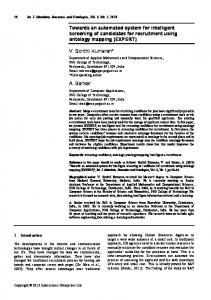
Data Acquisition The acquisition system consists of a LCD640 projector and a CCD camera. The acquisition method for estimating the 3d -shape of a sherd is shape from structured light [PT96], which is based on active triangulation. The projector projects stripe patterns onto the surface of the objects (Fig. 2). In order to dis tinguish between stripes they are binary coded. The camera grabs gray level images of the distorted light patterns at different times. With the help of the code and the known orientation parameters of the acquisition system, the 3d-in formation of the observed scene point can be computed [KKS96]. This is done by using the triangula tion principle. The image obtained is a 2D array of depth values and is called a range image (Fig. 3a).
Fig. 2: Configuration with light projector, camera and object (a) and Fragment with stripe patterns (b)
Registration Registration is the process of aligning two or more views of an object from a scene, in our case the front- and the back-view of the sherd. These views can be represented as either intensity images or range images. An intensity image is a grey level or colour image, whereas a range image is a 2D array of depth values, which can be obtained by our range scanner. Fragments of vessels are thin objects, therefore 3d-data of the edges of fragments are not accurate and this data can not be acquired without placing and fixing the fragment manually. Ideally, the fragment is placed in the measurement area, a range image is computed, the fragment is turned and again a range image is computed. To perform the registration of the two surfaces, we use a-priori information about fragments belonging to a complete vessel: both surfaces have the same axis of rotation since they
belong to the same object. Furthermore, the distance of the inner surface to the axis of rotation is smaller than the distance of the outer surface. Finally, both surfaces should have approxi mately the same profile, i.e. the thickness of the fragment should be more or less constant.
(a)
(b)
(c)
Fig. 3: Range image of a fragment (a), Front view (b) and Back view (c) Archaeological pottery is assumed to be rotationally symmetric since it was made on a rotation plate. With respect to this property the axis of rotation is calculated using a Hough inspired method [YM97].
Fig. 4: 3d surface reconstruction overview Fig. 4 gives an overview of a 3d-surface reconstruction from two object views. The first step consists of sensing the front- and backside of the object (in our case a rotationally symmetric fragment) using a calibrated 3d-acquisition system. We register the resulting range images by calculating the axis of rotation of each view and bringing the estimated axes into alignment. The method is described in detail in [KS99].
Fig. 5: Front- and back-view (range images) and their axis of rotation of a flowerpot (a, b) and an archaeological fragment (c, d). To find out if the method is working on real data we used a totally symmetric small flowerpot with known dimensions and took a fragment which covered approximately 25% of the original surface. The range images of the front- and back-view consisted of approximately 10.000 surface points each (Fig. 5a, b). The mean distance d between the surfaces is 5.64mm and the registration error δ=1.42mm. The distribution of the registration error delta for the flowerpot is shown in Fig. 6a. The registration error increases towards the top of the pot, because of the irregularity of the distance between the surfaces at
that region since the flowerpot has an edge (upper border) where inner and outer surface are not parallel.
(a)
(b)
Fig. 6: Distribution of δ for registered flowerpot (a) and archaeological fragment (b) Fig. 5c and d show the front-view, back-view and the axis of rotation of a real archaeological fragment. Registration tests with this fragment resulted in regis tration errors of approximately δ=1.7mm and a mean distance of d=5.8mm. Fig. 6b shows the distribution of δ of a registered archaeological fragment. Marginal peaks are caused by shadow regions of the back-view (see Fig. 5d) at the border of the fragment, where either no range data is processed or the range information is unreliable. The increase of the registration error δ reflects the uneven surface of the fragment. Further problems that arise with real data are symmetry constraints, i.e. if the surface of the fragment is too flat or too small; the computation of the rotational axis is ambiguous (worst case: sphere) which results in sparse clusters in the Hough-space, which indicate that the rotational axis is not determinable.
Profile Estimation The processing of the profile begins with an estimation of the proper orientation of the sherd, because the calculation of several measurements (e.g. heights, diameters, etc.) depends on it. To estimate the longest profile line we use the orientated sherd. This profile is supposed to be the longest elongation along the surface of the sherd parallel to the rotational axis through two points. This profile line is located where the fragment has its maximum height. The height is defined as the orthogonal distance from a point of the sherd to the orifice plane of the object. With the parameters of a plane that intersect the fragment where the longest profile line is located the distances between the plane and each vertex of the 3D-model are calculated. Then the nearest 1% of points are selected as candidates for the profile. For each of those vertices all the patches they belong to are filtered through a search in the patch list with their index number. In Fig. 7a sherd colored by the value of distance is shown (lighter means nearer to the intersecting plane). Every patch is a triangle, which consists of three points that are connected through three lines.
(a)
(b)
Fig. 7: Properly oriented sherd and intersecting plane for profile extraction (a) Estimated oriented profile with extremal points for classification (b) The position is calculated for all these three combinations of pairs of points of the filtered patches. The Hessian normal form is used to calculate the distances between the points and the plane. We use the sign of the distances, which corresponds to the side of the plane on which a point is located. Every pair of vertices that has both points on different sides of the plane is part of the profile line, because its connection intersects the plane. The coordinates of these pairs are rotated into the xy -plane and the zcoordinate is removed. This result is a properly oriented profile line (Fig. 7b).
Segmentation Following the manual strategy of the archaeologists, the profile should first be segmented into its parts, the so-called primitives, automatically. The profile determined has to be converted into a parameterized curve [HM95] and the curvature has to be computed [MSK95]. Local changes in curvature [RN97]} are the basis for rules required for segmenting the profile. Our approach is a hierarchical segmentation of the profile into rim, wall, and base by creating segmentation rules based on expert knowledge of the archaeologists and the curvature of the profile. The segments of the curve are divided by so called segmentation points. If there is a corner point, that means a point where the curvature changes significantly, the segmentation point is obvious. If there is no corner point, the segmentation point has to be determined mathematically.
Fig. 8: S-shaped vessel: profile segmentation scheme
Several points characterize the curve, Fig. 8 shows the segmentation scheme of an S-shaped vessel as an example: ◊
IP (inflexion point): point, where the curvature changes its sign, that means where the curve changes from a left turn to a right turn or vice versa;
◊
MA (local maximum}: point of vertical tangency; point, where the x-value is bigger than in the surrounding area of the curve;
◊
MI (local minimum): point of vertical tangency; point, where the x-value is smaller than in the surrounding area of the curve;
◊
OP (orifice point): outermost point, where the profile line touches the orifice plane;
◊
CP (corner point): point, where the curve changes its direction substantially;
◊
BP (base point): outermost point, where the profile line touches the base plane;
◊
RP (point of the axis of rotation}: point, where the profile line touches the axis of rotation;
◊
SP (starting point): in case of vessels with a horizontal rim: innermost point, where the profile line touches the orifice plane;
◊
EP (end point): in case of fragments: arbitrary point, where the profile line ends;
(a)
(b)
Fig. 9: properly oriented sherd with intersecting plane (a) and inner and outer profile with extremal points for classification (b) By means of these curve points several main segments of a vessel are distinguished: rim, upper part, lower part, neck, shoulder, belly and bottom. Different kinds of vessels can be classified on the basis of the number and characteristics of these segments. Segmentation is done only on the outer half of the profile [OTV93], because the inner side does not contain information about the vessel's class in the form of curvature. So the profile is divided in the outer and inner profile at the orifice and the bottom point, which is calculated by knowledge of the orientation. The next step is to split the outer profile into its primitives by locating the characteristic points. A detailed description of the algorithm can be found in [KS02] The primitives computed and the relations form a description language; different profiles have different descriptions. Next, a classification process tries to find different fragments belonging to the same vessel based on attributes stored in the archive database. After that, the profile of the fragment can be used to reconstruct the original (complete) vessel. This includes the possibility of reconstructing missing parts of the vessel and the search for possible matches of other fragments already stored in the
archive with the one that is under consideration (part-assembly). The classification of newly found fragments of an unknown type will be performed by comparing the description of the new fragment with the description of already classified fragments by computing the graph similarity. Dual Graph Contraction (DGC) preserving most discriminative properties can be used to reduce the high computational complexity of pairwise comparison. The generalised sub-graph with the highest graph similarity can be used to reconstruct the complete vessel. Each fragment has a unique number when entered in the stratigraphy tool [Green02]. Together with all attributes the fragment is stored in the database. Fig. 10 describes an example of the retrieval. The left side shows the profile classified as bowl. The primitives are the basis for the classification and reconstruction process. On the right hand side of Fig. 10 a fragment that is not yet classified is depicted, thus the type of vessel is not yet known. Its profile is to be matched against those in the database. The type of fragment can be classified as bowl. Furthermore, missing parts of the fragment (like the base in this case) can be reconstructed based on the already stored information.
Structured Database
Unknown Fragment
Fig. 10: Fragment Retrieval Test material for reconstructing a complete pot out of its fragments was selected (100 different pieces and five examples of fragments of the same object). Fig. 11 shows fractured vessels that are glued together by archaeologis ts and fragments belonging to the same object.
Fig. 11: Test material: Fragments belonging to the same object
Preliminary tests have been worked out on the restoration of a complete pot out of one of its fragments. Therefore the profile of a fragment has been estimated. Next it was manually oriented in 3D-space (see Fig. 12a) and rotated by 360 degrees. Fig. 12b shows the rotated profile with mapped texture.
(a)
(b)
Fig. 12: Rotating the profile in order to get a 3D Model of the fragment
Conclusion We have proposed a system for automatic archivation of pottery. The work was performed in the framework of the documentation of ceramic fragments. We demonstrated a model based technique that computes and uses the axis of rotation of fragments belonging to the same vessel to bring two views of a scene into alignment. We used a robust technique to determine both surface normals and the rotational axis. The method has been tested on synthetic and real data with reasonably good results. It is part of continuing research efforts to improve the results from various range images since the technique depends on the correct determination of the rotational axis of one surface. Furthermore we want to conduct intensive tests with real archaeological fragments within the 3D-MURALE project [KS01] that are selected, provided, and evaluated by archaeologists.
Acknowledgments The authors would like to thank Prof. Marc Waelkens and Roland Degeest from the Katholieke Universiteit Leuven, Eastern Mediterranean Archaeology, and Kristina Adler and Martin Penz from Vienna University, Institute of Classical Archaeology for their archaeological support and contributions in evaluating the profile representation approach and for helpful and inspiring discussions.
References [GCT02] Green, D., Cosmas C., Itagaki T., "The Heritage Of Stratigraphy - Visualizing Legacy Data". in: G. M. Cortelazzo and C. Guerra (Ed.), " 3DPVT02: 1st IEEE Intl. Symposium on 3D Data Processing Visualization and Transmission", Padua, Italy, pp.750-753, 2002. [HM95] Z. Hu and S.D. Ma. The Three Conditions of a Good Line Parameterization. Pattern Recognition Letters, 16:385– 388, 1995. [KKS96] R. Klette, A. Koschan, K. Schlüns. Computer Vision. Räumliche Information aus digitalen Bildern. Vieweg Verlag, Braunschweig/Wiesbaden 1996. [KR02] Kampel M., Sablatnig R., "Automated Segmentation of Archaeological Profiles for Classification", in: Kasturi R., Laurendeau D., Suen C., (Eds.), "Proc. of 16th International Conference on Pattern Recognition", Vol.1, pp.57-60, 2002. [KS00] M. Kampel, R. Sablatnig, Colour Classification of Archaeological Fragments, In: "Proc. of the 15th International Conference on Pattern Recognition, Vol.4, pp.771-774, 2000.
[KS01] Kampel M., Sablatnig R., "On using 3D Multimedia Tools to measure, reconstruct and visualize an Archaeological Site", in: Forum Archaeologiae, Zeitschrift für klassische Archäologie, Vol.19, No.IV, 2001. [KS99] Kampel M., Sablatnig R., "On 3d Modeling of Archaeological Sherds", in: Sarris N., Strinzis M.G., (Eds.), "Proc. of Intl. Workshop on Synthetic-Natural Hybrid Coding and Three Dimensional Imaging", pp. 95-98, 1999. [MSK95] J. Matas, Z. Shao, and J.V. Kittler. Estimation of Curvature and Tangent Direction by Median Filtered Differencing. International Conference on Image Analysis and Processing Pages 83–88, 1995. [OTV93] C. Orton, P. Tyers, A. Vince. Pottery in Archaeology, 1993. [PT96] F. DePiero, M.Trivedi. 3-D computer vision using structured light: Design, calibration, and implementation issues, Advances in Computers, 43:243-278, 1996. [RN97] A. Rosenfeld and A. Nakamura. Local Deformations of Digital Curves. Pattern Recognition Letters,18(7):613–620, July 1997. [YM97] S. Ben-Yacoub, C. Menard. Robust Axis Determination for Rotational Symmetric Objects out of Range Data. In Burger. W, Burge M., Editors, 21st Workshop of the OEAGM, pp.197-202, Hallstatt, Austria, May 1997.