NETOMAC Real-Time Simulator - Standard Test Modules for Enhanced Relay Testing Rainer Krebs Olaf Ruhle* Siemens AG Erlangen, Germany
[email protected]
Abstract: Protective relays play an important role in today’s complex power generation, transmission and distribution systems. Consequently, this process has given rise to the need for more broad-based dynamic automated testing. For this, a PC-based real-time simulator for relay testing was developed in the last years, including the capability of automated closed loop testing. The simulation program NETOMAC [1] is used for generating the output signals under real time conditions. The Digital Network model DINEMO (digital network model) [4], a unit for real time communication, is able to put out the real time computed signals to the relay. The system response, like a trip signal to open a breaker is connected back to the PC and the NETOMAC breaker model can be controlled as in the real system. Additionally an interface output of the simulator system to standard test hardware for offline testing was developed in the last year. The use of the simulation program NETOMAC allows the simulation and testing of nearly any fault event, e.g. evolving faults, saturation effects or power swings. High end test modules for all kinds of protection devices like line protection, transformer protection, busbar protection, generator protection and machine protection are available which can be used easily for testing protection devices.
olaf.ruhle@ siemens.com
end testing including all transient phenomena. Additionally the simulator surface NETDRAW for automated relay testing, which uses special testing strategies and high end test modules with detailed models is described in this paper. 2
SIMULATOR EQUIPMENT
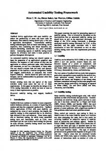
Digital simulator testing can be used to evaluate the performance of digital relays under realistic conditions. In the last years, Siemens AG in cooperation with the Technical University of Berlin has developed a PC-based real time simulator for digital relays, special computers are not necessary. This system includes the capability of transient in-the-loop testing of modern protective relays. Fig. 1 shows the block diagram of the digital simulation system. The NETOMAC program (network torsion machine control) is used in order to determine the currents and voltages under real time conditions for transient testing of protection equipment [6].
Keywords: Electromagnetic and electromechanical transients, NETOMAC®, Real-Time-Simulation, Relay Testing, Training Simulator, Test Automation.
1
INTRODUCTION
Due to the decreasing calculation time of modern PC’s NETOMAC has been able to simulate large power grids under real-time conditions in the last years. Since 1996 NETOMAC has been commercially used as realtime simulator for interactive testing of protection devices [7]. The frequency domain for modeling power grids reaches from extremely fast traveling-wave phenomena on overhead power lines to the slow control phenomena of steam systems. This paper describes the NETOMAC real-time simulation abilities for instantaneous value calculations and also for stability calculations for testing real equipment. In opposite to large hardware-based real-time simulator systems, NETOMAC is a PC based low cost real-time simulator system with only a minimum on hardware costs, which allows high
Fig. 1: Real Time Digital Network Model
DINEMO (digital network model) is a unit for real-time communication, which is able to carry out real time computed current and voltage signals [4]. The response of the real equipment, such as a tripping signal to open a breaker, has a feed back into the personal computer. In addition, because the simulation is running in real-time, the output contacts of the relay can be connected back to the NETOMAC circuit breaker models where the breakers can be controlled as in the real system. For realizing the communication between the personal computer an I/O-card with integrated CPU has been developed. Voltage-to-current
* Dr. O. Ruhle, Siemens AG, System Planning (PTD SE NC 5), P.O.Box 3220, 91050 Erlangen, Germany
converters are used for adaptation of the signal level between D/A-converters and test equipment. For open loop testing an additional interface output of the simulator system to standard test hardware was developed in the last years.
Additionally, if both, simulation and communication, is done by the PC, most of the disposable time is used for the communication. Therefore it is useful, to separate simulation and communication. 3.1
Improving Simulation Performance
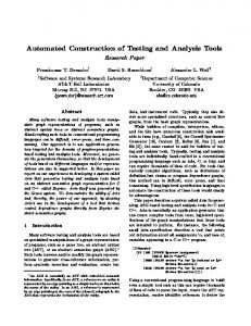
Realizing the closed loop testing approach, Technical University of Berlin developed a special interface card to connect the DINEMO and the personal computer. For that reason nearly 100% of the available time of the PC can be used for simulation. In this case a smaller time step for a better real time simulation becomes possible [7]. The principle increase of simulation time using this way is shown in Fig. 4. Besides, the number of signal channels has no more influence on the simulation time. Fig. 2: Offline Standard Test Equipment
Fig. 2 shows the simulator for dynamic testing with standard test hardware. It can be used in combination with a laptop for dynamic relay testing. The complete range of dynamic test equipment is also available for open loop conditions. At the end COMTRADE standard files can be created automatically for each test case. This offers the possibility to use any hardware for dynamic testing. Fig. 3 shows a NETOMAC created COMTRADE file using the SIGRA COMTRADE viewer.
Fig. 3: COMTRADE results
3
Fig. 4: Improving communication performance
The PC has to write out all data as fast as possible to gain more time for the simulation. As a logical consequence, there is an input and output buffer on the I/O-card between ISA-bus and the SCSI chip. All data to be sent from PC to DINEMO are written in a First-In-First-Outregister (FIFO). The time needed to transfer the data simulated from PC to the input buffer of the I/O card amounts a few s per value. After this short time, the PC is no longer blocked for the communication and the simulation of the fault continues. On the other side, all replying data received from DINEMO are written in an output register. After writing the data simulated in the FIFO input buffer of the I/O-card, the PC analyses the output register containing the actual status of up to 16 replying signals of the relays to be tested in the closed-loop.
CLOSED LOOP TESTING
In many situations the closed loop testing approach enhances efficiency in the conduct of the tests. Also, in other situations, closed loop testing is a requirement for properly determining the response of the equipment. In case of interaction, the sampling rate is a requirement for the quality of the output signals. The time needed for the simulation depends on the simulator and the complexity of the simulated network.
3.2
Asynchronous Data Transfer
In case of designing and testing real equipment, digital dynamic power system simulation should reach or even be faster than in real-time. A mainly bottleneck is the occurrence of alterations of the nodal admittance matrix, e.g. due to a switching operation. Additional to the calculations, that are executed during a normal integration time step, a new preparation of the
matrix is necessary. For that, discontinuous timesteps slow down the fastness of the simulation process. In case of closed-loop testing, which may dictate real-time conditions, the output rate has to adapt to the slowest simulation time-step. Real circuit breakers always have a time lag between the tripping signal of a relay and connection or disconnection. The time lag ranges from 40ms to 60ms. This phenomenon can be used to eliminate the influence of discontinuities [7]. Improving the performance of the closed loop testing approach, the buffers of the I/O-card are used, not only to separate simulation and communication. They are also used to buffer a number of pre-simulated output samples on the I/O-card before writing-out to the relay. When starting the interactive process, the first buffered sample is carried out to the relay in real-time and the action of the tripping response creates dynamic conditions on the simulated power system with a time-delay. This delay is dependent on the buffered rate of pre-simulated time steps.
voltage transformers. The test environment is handled by the GUI NETDRAW for example for line protection, transformer protection, busbar protection, generator protection and machine protection.
Fig. 6: Standard test modules for relay testing
The test modules are developed in graphical comfortable surfaces which can easily be used in combination with standard hardware test units, e.g. DINEMO or only as COMTRADE creator. Each of these units is running under the GUI NETDRAW with a complete test environment dependent on the relay type including fixed network models and special test cases.
Fig. 5: Closed-loop testing approach
Fig. 5 shows the interactive testing process using the buffer approach. The pre-simulated time-interval is equal to the adjusted time lag of the circuit breaker model. In cases of simulating continuity faster than real-time, the system is able to fill the buffer again. The whole point of the closed loop testing approach is that the buffer is decreasing simulating discontinuities and is increasing, simulating continuities. However, these movements have no influence on the adjusted time lag of the circuit breaker and the real-time condition. The system will lose the closed loop ability, if the buffer gets empty. 4
TEST MODULES
For the NETOMAC simulator system high end test modules for all kinds of protection devices are developed including detailed models for mutual coupled transmission lines, complex transformers, real current transformers and
Fig. 7: Transformer models
For transformer protection detailed models for 2-winding transformers, 3-winding transformers and auto transformers with magnetization and hysteresis effects can be used.
Fig. 8: Transformer magnetization
The grid topology of the models is not fixed and the parameters of the components can be changed easily. For all units various fault conditions (e.g. single phase faults, three phase faults, transformer switching, interruption breaker switching etc.) are available. Detailed realistic models for current transformers and voltage transformers make it possible to simulate non ideal effects like ct-saturation and cvt-transients.
Fig. 11: Autoreclosure Testing
Additionally to fixed network models all this standard test modules can be supplied with special model libraries, orientated on the customers transmission system configuration. 5
AUTOMATED TESTING
Protective relays play an important role in today’s complex power transmission and distribution systems. This process has given rise to the need for more broad-based dynamic automated testing. User Interface Modul
Fig. 9: Simulation of ct-saturation effects
Test Results (Data Base)
Arcing faults and multiple faults (evolving faults) with clearing before tripping are also included in the software. Additionally power swings and more machine problems can be simulated.
Test Control System
Fault Detection • Feature Extraction • Reference System • Heuristic Classification
Transient File Generation (NETOMAC)
I/O Support (DINEMO)
Fig. 12: Automated testing
Fig. 12 shows the block diagram of additional evaluation software. NETOMAC is used for simulating the output signals under real-time conditions. The fault detection module detects differences between the behavior of the relay and its internal specification. The test results have a feed back into the test control unit. For this it is possible to optimize testing using testing strategies. Fig. 10: Testing of power swings
When the simulator is running under real time conditions (DINEMO hardware) auto-re-closure testing is also possible.
5.1
Testing Strategies
Except for the idea of informal manual proofs, the entire concept of proving program correctness is of no practical use today. Therefore due to economical aspects protection equipment will be evaluated by testing. In order to find discrepancies between the protection software and its external specification, statistic and systematic testing are useful strategies. The emphasis of the statistic approach is the testing
with all kinds of dynamic fault conditions. In opposite to this, the systematic method is more orientated on the external specification of the relay.
start
Testcase Generation random process
I/O Support (DINEMO)
Fault Detection
Fault features
Systematic Testing Systematic testing uses cause-effect-graphing for segmenting the external specification into individual functions. The art of test case design is really the art of selecting those test cases with the highest yield. Furthermore, each test case should represent a class of inputs. For that, systematic testing with only a little testing investment is possible. Fig. 13 shows a block diagram of the systematic testing approach. Before testing a special part of the software, the relay is configured for evaluation these function. Each segmented function is tested with a special designed rate of test cases. If an error occurs, the fault diagnosis module attempts to find symptoms for each error. Refinements consist in deciding which components of the module are faulty. Input Data (Relay) Testcase Generation start
Active Relay function
Diagnosis Module
Testing Control Unit
Transient File Generation (NETOMAC)
• Symptoms
Fault Detection Knowledge Base
Knowledge Base
Data Acquisition
Restriction of fault area
Testcase Generation (random process)
No
Yes
n[k] > n[k-1]
Fault Detection
I/O Support (DINEMO)
Fault Classification
Fig. 14: Method of successful approximation
Starting this process, a sampling with large extension is tested. All errors, which occur during this process, are stored in a buffer. In addition, the reliability of the relay is estimated in this test. After testing all cases, each stored type of error is investigated separately. The system will rule out the limits in which this type of error occurs. 5.2
Relay Testing
Fig. 15 shows an example of a transmission line relay on auto-re-closing. The relay creates dynamic conditions on the simulated power system which are dependent on the timing of the initial response and action of the relay.
I/O Support (DINEMO)
Fault Classification
Fig. 13: Systematic Testing
Statistic Testing Statistic testing is used for reliability control of protection equipment. In this case, the test data are generated automatically. For that, every fault case has the same probability to be tested. The extend of the sampling is dependent on the failure of the reliability estimation. In case of economical aspects, a strategy is implemented, using sampling testing in combination with a method of successive approximation to find discrepancies between the software and its external specification. Fig. 14 shows the schematic of the test procedure.
Fig. 15: Auto-re-closing process
Varying the dynamic fault conditions a large number of test cases are available. The extent of the test is optional. Performance indices are used to quantify the reliability of the tested protection system. Fig. 16 shows an example for a systematic test result. In this case a distance line protection relay was tested. Time zone 1 was adjusted on 85% of the transmission line length.
magnetic phenomena in a/c. systems", "Elektrizitätswirtschaft", No. 1 (1979), p. 18 23, Germany
Fig. 16: Systematic test results
6
Interactive dynamic automatic testing of protection devices Interactive testing of controller structures
Stability mode
Interactive testing of controller structures Advanced Training Simulator for very large interconnected systems
Region
Loop
Application
Instantaneous value mode
-
HVDC - Simulation
24 puls Bridge
Instantaneous value mode
closed closed
Relay Testing Controller siting
150 nodes, 2 generators 150 nodes, 5 generators
System extension 1.2 to global real-time t=100s 3.0 to exact real-time t=250s exact real-time t=1 ms
Stability mode Phasors
open closed
Training Simulator Controller siting
400 gen., incl. controller 100 gen., incl. controller
t=30ms t=30ms
System extension
Time step
global real-time exact real-time
Fig. 17: Real-time simulation performance
The simulator surface NETDRAW can be used for creating COMTRADE files, for open loop relay testing with standard test hardware and for advanced closed loop testing using DINEMO.
7
Kulicke B:, Winter, W.: “NETOMAC Real-Time Applications on Power Systems”, AKTR-Forum 1999, FGH, Mannheim, Germany
[4]
Kulicke, B.; Pannhorst, D.; Winter, W.; Eickmeyer, D.: "Hardware-in-the-loop test using the real time simulator NETOMAC", ICDS '97, Montreal 1997, Canada
[5]
P Lehn, J. Rittiger, B. Kulicke, „Comparison of the ATP Version of the EMTP and the NETOMAC Program for Simulation of HVDC Systems“, IEEE Winter-Meeting, New York, Feb. 1995
[6]
X. Lei, E. Lerch, D. Povh, O. Ruhle: A large Integrated Power System Software PackageNETOMAC, Powercon 98, Beijing, China, 1998
[7]
Winter, W.: “Automated Interactive Real-Time Testing of Digital Protection Devices using Testing strategies”, VDI Verlag, Düsseldorf 1998, ISBN 3-18-325421-2
CONCLUSION
The NETOMAC simulator is a very powerful tool for PC-based interactive real-time simulation. Due to the rapid development of new efficient microprocessors smaller simulation time steps can be expected in future. The NETOMAC simulator for testing external hardware or protection relays is able to run in closed loop and open loop using DINEMO or standard test hardware as output hardware units. External hardware like voltage regulators or FACTS devices can be tested in instantaneous value mode or stability mode. In this case pre-simulation technique is not possible. Fig 17 shows the actual NETOMAC simulation performance. Instantaneous value mode
[3]
REFERENCES
[1]
Kaiser, S.; Winter, W.: "New approach for improving the performance of digital real-time simulators", Patent Application, GR 97 P 8621 DE, SIEMENS AG, Berlin, FRG
[2]
Kulicke B.: "NETOMAC digital program for simulating electromechanical and electro-
Olaf Ruhle was born in Germany in 1965. He received Dipl.-Ing. and his Ph. D. degree in electrical engineering from the Technical University of Berlin in 1990 and 1994 respectively. Since 1993 he is a member of Power Transmission and Distribution Group and the system planning department at Siemens in Erlangen, Germany. He is working on power system stability, dynamics of multimachine systems, control, optimization and identification problems in electrical power systems. He is responsible for the program system NETOMAC support, sale and training worldwide. He is visiting professor at several universities. Rainer Krebs was born in Pfedelbach, Germany on January 19, 1958. He received his Dipl.-Ing. degree in Electrical Engineering and Power Systems in 1982 and the Dr.-Ing. degree in 1990 from the FriedrichAlexander University, in Erlangen. He joined the ‘Institut für Elektrische Energieversorgung’ at the same University in 1983, working on calculation and measurement of power-system disturbances and unbalances, using space-phasor theory. In 1990 he joined the Siemens AG in Erlangen as a member of the System Planning Department. He started his work in the fields of power-system planning, power-system relaying, system and protection real-time simulation and fault analysis. Since 1998 he is director of the department ‘Protection Systems and PC-Tools’. He is member of VDE and its associated section ETG.