Automated Code Compliance Checking Based on a Visual Language and Building Information Modeling Cornelius Preidela and André Borrmanna a
Chair of Computational Modeling and Simulation, Technische Universität München, Germany E-mail:
[email protected],
[email protected]
ABSTRACT One of the most important issues during the planning of a construction project is to maintain the quality of the design planning constantly at a high level. Therefore this quality must be checked continuously in terms of accuracy and compliance to the applicable codes and guidelines throughout the duration of a project. Nowadays this checking process is laborious, cumbersome and error-prone since it is mostly performed manually based on twodimensional planning and iteratively at each planning change by the responsible planning consultant. Recently, various approaches attempted to automate this highly relevant process with the help of digital methods, such as Building Information Modeling, in order to reduce the amount of work and increase the quality of the planning at the same time. Although this Automated Code Compliance Checking has been implemented using a variety of different methods, most of the existing approaches fail because they represent the information of rules in an insufficient or overly complex manner. In this paper a short analysis of the pros and cons of selected existing approaches is given and subsequently minimal requirements for a successful automation of this process are defined. To counteract the lacks and insufficiencies of existing approaches, a new method is introduced which enables an automation using a flow-based, visual programming language, which we call Visual Code Checking Language (VCCL). Finally the practical implementation of a semi-automated compliance check concerning an exemplary German fire code demonstrates the viability of the approach. Keywords – Automated Code Compliance Checking; Building Information Modeling; Visual Language; ISARC 2015
1
Introduction
Standards and guidelines in construction industry are used for standardization of requirements and secure the technological standards in order to guarantee the
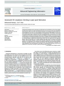
structural stability, reliability, quality of material and not at least the safety of the user. Therefore the compliance check of the design planning concerning the applicable rules and regulations represents an essential process during the execution of a construction project. Due to the variety of disciplines and subject areas in the building industry a large amount of codes and regulations have to be taken into account by the planning consultant, from who a high level of expertise, experience and care is demanded accordingly. Case examples and requirements in guidelines, as shown in Figure 1, can be presented in many different ways, ranging from simple and clearly structured tables with limiting values over graphical representations to flow-text written descriptions.
“The access route for pedestrians / wheelchair users shall not be steeper than 1:20. For distances of less than 3 metres, it may be steeper, but no more than 1:12. The access route shall have clear width of a minimum of 1,8 m and obstacles shall be placed so that they do not reduce that width.” Figure 1. Top: Illustration of a spatial case of fire according to the German standard DIN 1823211:2007 [1] Bottom: Excerpt of the Norwegian accessibility guideline, NS 11001-1.E:2009 [2] Nowadays the checking process is performed to a large extent manually based on two-dimensional technical drawings and textual documents by the responsible planning consultant as well as the building permission authorities. Due to the low level of automation the common checking procedure is timeconsuming, tedious and error-prone. This is particularly evident when unwanted iteration cycles become
necessary due to modifications demanded by the respective authorities or errors in the construction processing. As a result, checking the code compliance of the building design can be a major cause of delays and cost increases in construction planning. Recently significant delays of several major projects in Germany have shown the impacts of a wrong execution of checking processes. Therefore the public and political interest has grown and have contributed to an increased demand for an optimization of construction processes with the help of modern digital tools [3]. Due to the continuing development of new technologies in the recent years, the construction industry is undergoing a fundamental transformation, which was initiated in particular by the methodology of Building Information Modeling (BIM). By means of new digital methods and the rapid crosslinking of increasingly powerful computers new practices and research areas arise offering a range of new approaches to make building processes more efficient [4,5]. As a result the construction industry has gained the necessary resources to automate and thereby optimize the checking process in terms of effort, time and cost. During the BIM planning process all information is stored in a central digital building model, which in turn provides all the current information for all project participants throughout the entire life cycle of the building. It is recommendable to use these already bundled data for a full- or semiautomatic review of a model for compliance with standards, so that finally the overall process achieves a higher level of efficiency.
2
State of the Art
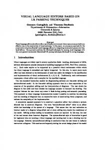
In the recent years various efforts were undertaken in order to develop a method for Automated Code Compliance Checking. In this paper some important representatives of such methods are presented, and subsequently the challenges and difficulties are discussed. In Figure 2 chronological sequence of the treated approaches is shown. Solibri Model Checker CORENET BP-Expert
CORENET ePlanCheck Fornax
BERA
1995
2000
2005
2010
2015
Figure 2. Representative approaches for Automated Code Compliance Checking in the recent years (inspired by [6])
2.1
CORENET & FORNAX
In 1995, the Singaporean building construction authority (BCA) started the platform “Construction and
Real Estate Network” (CORENET) with the intention to optimize the collaboration and interaction between all the participants of a building project with special emphasis on incorporating the responsible authorities [7]. Accordingly, the quality control of the design, including code compliance checking, is of particular importance for CORENET and was introduced as a separate module called “CORENET e-Plan Check” in 2002. The provided checking functionalities focus on the national applicable codes in the areas of building control, barrier-free access und fire safety [8]. The main component of the code checking system is the FORNAX library which has been developed and maintained by a private company [9]. As a consequence the correctness of the implementation is not verifiable since the hard-coded checking routines are not transparent for the user. Therefore this checking functionality is called a black-box method [10,11]. Nevertheless CORENET represents one of the most comprehensive approaches in the area of Automated Code Compliance Checking since it covers a large part of the Singaporean guidelines and is used in over 2500 companies of the AEC sector [9]. At this point it should also be mentioned that the introduction of CORENET was heavily promoted by the Singaporean government and accompanied by appropriate legislation. As a consequence construction companies in Singapore were brought to the use of CORENET as they may otherwise not receive a building permit for the construction projects. Taking the special political, economic and demographic structure of this country into account, it remains doubtful that such an approach would prevail in the same way in a European country.
2.2
Solibri Model Checker (SMC)
In the year 2000, the Finnish software company Solibri introduced the Java-based Solibri Model Checker, which was intended to be a validation and optimization tool for digital building models stored in the Industry Foundation Classes (IFC) data format. In the Rule Manager component, the SMC provides a library of rules and guidelines, from which the user can select and build up an individual review process according to his requirements [9]. Next to basic rules, which check the quality of the imported IFC model, the manager provides mainly geometry-oriented rules e.g. in the field of space management and accessibility. The rule sets within the SMC are implemented as hard-coded functions, which access the information of the data model via a native programming interface. Since this interface is not available to the public, also the SMC implements a blackbox method, which makes no information of the process visible for the user. An external development of new or
custom rule sets is only possible in cooperation with the company Solibri.
2.3
Building Environment Rule and Analysis Language (BERA)
Next to the to many directly implemented black box methods, there are approaches that introduce a languagebased Code Compliance Checking. A significant representative is BERA, a domain-specific programming language, which has been developed not only for querying but also for the formulation of checking processes for digital building models [12]. Since this is a language-based approach, which grants much more manoeuvrability for users, it distinguishes itself clearly from the methods discussed above. The transparent description of procedures and the direct influence of the user result in a higher potential to encode more complex rules. As a proof of concept, BERA has already been applied for first evaluations of buildings circulation and spatial programmes. To this end the language provides a set of spatial operators for the definition of rules in the context of these application areas [9]. In summary BERA shows the high potential of language-based methods and that this can be an important point of departure. Nevertheless this approach lacks a generality in the logic base, which is necessary to achieve a higher versatility especially to define more complex structures.
3 3.1
Challenges of an Automated Code Compliance Checking Common Structure
In order to demonstrate the challenges of the technical implementation of an Automated Code Compliance Checking the basic structure of the overall process has to be identified first. Although each of the presented approaches is characterized by its individual features, a common structure of the compliance checking process can be found. Eastman [9] defines the overall process as a flow and interaction of four single process steps, shown in Figure 3. The main requirement and first step of any compliance review is the translation of rules into a machine-interpretable language. The idea of the digitization of language in oral or written form exists since the early days of computer science and is still a highly relevant topic in the various application areas. Basically it is about to translate the content of spoken or written word as precisely as possible into binary code [13]. Since guidelines and standards describe the contented information usually in many different ways, it is a major challenge to standardize this process.
Building Model Preparation
Rule Interpretation
Rule Execution
Report Checking Results
Figure 3. Common structure of an Automated Code Compliance Checking process (inspired by [9]) In a next step the digital rules are read from an executing instance, interpreted and processed on base of information, which is provided by the digital building model. Various investigations have shown that this step can be a major error source due to inconsistencies, contradictory, false or non-existent information in the building model [14]. A direct use is therefore not recommended, but to prepare the required information separately and in a pre-processing step. In a last step, the results of the review are finally processed and retained for the user. In the more modern approaches of an Automated Code Compliance Checking this process step is designed primarily graphically.
3.2
Major Challenges
As shown in Section 2, there are a lot of different approaches for an automation of the compliance checking. Nevertheless several factors can be found, which relativize this already reached degree of automation: Most of the existing approaches lack because of the insufficient transparency and visibility of the processing steps for the user. Many methods focus too much on the automation of the checking process and do not consider the incorporation of the user and therefore the practical applicability. The correctness and accuracy of a compliance checking is the responsibility of the reviser and cannot be transferred to a machine because of legal reasons. Therefore in building practice it is common to manually verify and validate the results with simultaneous or trailing plausibility checks, e.g. by rough calculations by hand or comparison with empirical values. Such a validation based on the experience of the reviser is not possible if the transparency of each single process step is not given. Because of its hardcoded machine-rules the SMC represents such a black-box method and so it fails in this point [8]. As a result an automated checking must be a dynamic and semi-automated process that moves the user into the focus and incorporates him into the process. Although the reviser has usually no programming skills, the human-readability of the translated codes must be maintained. Such a method is called white box and is schematically shown in Figure 4.
Black-Box
Input
Output
White-Box
Input
Output
Figure 4. Schematic representation of a black-box and a white-box method (inspired by [11]) Furthermore, many of the approaches focus on comparatively simple and straightforward rules. A transfer of this method to a higher level of complexity will be probably difficult, since the hard-coded and fixed implementation of rules cause a rigidity, which inhibit the formulation of complex rules. As a representative for language-based approaches, BERA has shown that the problem can be solved by creating a larger space of action for the translation step. According to the modular principle, complex structures can be build up by composing simple elements with a low degree of complexity, which are already well-defined and can be reused by the user. For this purpose it is necessary that the individual elements of the language are defined within a fixed logic frame, in order to implement a formal rigidness at the base.
languages. In recent years visual languages, which are also known as Visual Programming Languages (VPL), have been established particularly in the field of control and modification tools of digital information systems. Known software products in the context of building design are in particular the plug-in Grasshopper for Rhinoceros3D [15] or Dynamo for Autodesk Revit and Autodesk Vasari [16]. By adapting such a visual language to the specific needs of the Code Compliance Checking, the presented insufficiencies discussed in Section 3 can be overcome. The approach focusses in particular on the humanmachine-communication, which represents a previously defined, mandatory requirement for the success of an automation of the Code Compliance Checking. At any time and degree of completion of the visual processing system, the user is able to understand and inspect every single processing step, what is particularly important, since the reviewer is responsible for the accuracy and correctness of all compliance check results. If errors are identified in the processing chain, the system can be adjusted very quickly and simply according to the user’s requirements. With the help of such a visual language, it is possible to describe any compliance check without sacrificing the transparency for the user.
Finest Granularity
Genericity
VCCL
4
Visual Code Checking Language
The approaches in Section 2 have shown, that there are a lot of ways to automate the compliance checking, but there are still a lot of inadequacies. To overcome these insufficiencies we introduce a new approach, which uses a visual language for representing the Code Compliance Checking process.
4.1
Maximal Flexibility
Figure 5. Schematic principles of the VCCL
illustration
of
the
Methodological Basis
In general a visual language can be defined as a “formal language with a visual syntax and visual semantics”, which means that it represents a modular system of signs and rules using visual elements instead of textual ones on the semantic and syntactic level [13]. Information systems, which are described by a visual language can be interpreted much faster and easier by humans. Visual languages are often also called flowbased, since they display the complicated structures as a flow of information. The reason for the higher interpretation capability can be found in cognitive psychology, which states that visual information can be processed with two instead of only one hemisphere of the human brain in parallel. Schiffer [13] performs a detailed discussion of the advantages and disadvantages of visual
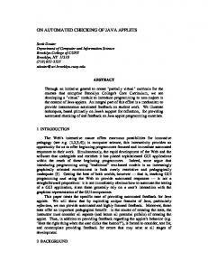
As shown in Figure 5 the VCCL follows three principles: genericity, finest granularity and maximal flexibility. The genericity describes the property of the VCCL that all elements must be defined as generic as possible regardless of the level of complexity. As a result each elements can be used in any situation and on any point of a desired structure. At the same time it must be possible to break down each element to its lowest level. This property of the VCCL is called finest granularity. These two features cause a maximum of flexibility for the user, who can formulate the desired content. Furthermore, a visual language is ideal for building a library of simple base elements, as it was introduced in Section 3.2. A schematic structure of such a library for the VCCL is shown in Figure 6.
VCCL Node Library Operators 0
Room X : Room
Objects
Basic Ops Relation Op* Iteration*
Data objects O
Other e.g. Table
Relation* set
Walls : set
Area : Float Height : Float
2
Base Graph
Complex Graph
Base Graph
Complex Graph
Complex Graph
n
VCCL Graph Library
set
Figure 8. Illustration of an attribute and set node A special form of an object node is a set of objects. In this node multiple objects of the same type can be stored. Principally it represents thus a special data type for an object node. An example of a set object is shown in Figure 8.
*planned
Figure 6. Schematic illustration of the VCCL node library and its resultant VCCL graph library with its ascending degrees of complexity The principle behind it is to make the overall process of compliance checking visible, by structuring this process in a compilation of composite process steps. Each of these elements is a single white box, which can be considered as a small module of the whole process. Therefore we introduce a modular principle, which can be used by any user even without profound programming skills. In this way we allow that any engineer can bring his professional skills and his experience into the process.
4.2
Wall 2 Wall n
degree of complexity
1
Base Graph
Wall 1
label description Operator Node
Figure 9. Illustration of an operator node on VCCL For the description of processes between object nodes the VCCL uses the operator node (see Figure 9). Such a node describes a well-defined operation on a specified number of input variables - the operands - and generates a corresponding result.
Elements of the VCCL
To define a new language, both base aspects semantics and syntax - need to be defined. In the following, the elements of each level and their graphical representation are presented for the VCCL.
Input-Port
Object Node : datatype label description
label datatype
Figure 7. Illustration of an object node on VCCL All elements of the semantic level are represented as nodes. The object node, as shown in Figure 7, describes an object that can be individually and clearly identified in a real-world system. Therefore it must be of a particular, unambiguously data type. For a better interpretation, attributes of objects can also be visualized as single elements (see Figure 8). The visualization of attributes is not obligatory and is only intended to let the user capture a complex flow of information.
Output-Port
Figure 10. Illustration of a generic node and its interfaces (called ports) and directed edges The elements of the syntactic level are represented as edges and interfaces. A directed edge links two VCCLnodes and thus builds up a processing chain. By defining the unambiguously direction of the edge, the representation of the information-flow is specified (see Figure 10). To describe the connection between VCCLnodes precisely, each semantic object has a certain number of interfaces (called ports) defining which information can be passed. In this way, the transmission of information across the processing chain is given a fixed frame and inconsistencies can be prevented. A port on the left side of a VCCL element is responsible for the incoming information and therefore is called Input-Port.
criteria “Wall”, which means that the operator extracts all building elements of type “Wall” from the building model. This is a common procedure, which can be applied for any attribute which is stored in the respective object. The result is finally transferred to the resulting set node.
Accordingly, ports on the right side are responsible for outgoing information and therefore called Output-Port. A schematic illustration of the different types of ports is shown in Figure 10.
4.3
Application of the VCCL
With these elements, it is possible to build up a VCCL graph, which describes a certain checking procedure. At the same time the process remains transparent and each process step visible as a single element of the information system. Building Model : Model
Wall : String
Model
Figure 13. Excerpt of the data table for the required smoke ventilation area in m² [1]
String Get Access
set
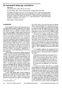
Since this is a very simple example, the application will now be shown for a more sophisticated case. In order to demonstrate the potential and versatility of the approach, a semi-automated compliance check regarding an applicable German standard is shown. A central regulation of the DIN 18232-2:2007-11, a German standard for the design of buildings in terms of smoke and fire protection represents a spatial case of fire (see Figure 1). Depending on the height of the room, the height of the smoke layer and the fire classification, the guideline requires a minimal smoke ventilation area that is listed in a data table, which is shown in Figure 13. The translation of this central regulation is shown in Figure 12 as a VCCL-graph. In this processing graph a single room is identified and afterwards its attributes are used to capture both values “Target area” and “Actual area”. The final result of this check is the comparison of these values, to check whether the limit value is met or not.
Wall 1 set
Set :
Wall 2
set
Wall n
Figure 11. VCCL graph describing the access to a certain data member An example of the VCCL for accessing wall components of a building model is illustrated in the following example, shown in Figure 11. In this example, both initial object nodes hold certain information of a defined data type and transfer it via the ports and the edges to the operator node. Inside of this operator the information of both elements is processed according the instructions that were assigned to the operator node. In this case, the model instance is accessed for the filter Room X : String
Building Model : Model Area : String
Model
String
Opening : String
Access Area : Float
String
Room
Height : Float
Room X : Room
set
Get Room
Opening X
Get Float
String
Float(*)
Get
Actual area: Float
(**) Special node, which can access a datatable and search for limiting boundary values according to certain criteria
Float
Float
Height : String
Openings : set
set
Area : Float
Room
Opening Y
String set
(*) Automatic sum up of all Float-attributes of the elements, which are stored in the object node
Necessary smoke ventilation area (**)
Float
Target area : Float Float
Comparison
Bool
Height smoke layer : Float Fire classification : String
String
Figure 12. VCCL graph describing the central regulation of the DIN 18232-2:2007-11
Result : Bool
4.4
Proof of Concept
In order to validate the concept of the VCCL a practical implementation of this language-based method was carried out and is presented in this section.
and the graph can be re-processed immediately. Furthermore the CodeBuilder focuses particular on the incorporation of the user in the checking procedure. Most of the nodes are able to display intermediate results of the processing procedure. As an example, relevant building elements, which fulfil or fail a certain check can be highlighted directly in the geometry view as shown in Figure 15. In this way, the user is able to check, if the processed result meets his expectations and requirements. The developed tool was examined for its practical applicability. To this end the central regulations of DIN 18232-2 discussed above were translated into VCCL and successful semi-automated. Exemplarily, the user interface as well as a result of a geometric checking, which stated an intermediate result of the VCCL processing, is shown in Figure 15.
5 Figure 14. User interface of the bim+ viewer [17] The application of the VCCL was developed and designed in close cooperation with the German software vendor Nemetschek [17]. As basis for the VCCL serves bim+, which is a standardized central platform for building information exchange. Next to a large number of basic functionalities, such as a web project management and a web viewer (see Figure 14), the platform provides an open REST-API, which enables developers to use the platform for their own purposes, such as the building information handling by the VCCL. We developed the CodeBuilder plugin, which allows the user to build up a VCCL graph using a library of elementary nodes. Since bim+ is used as a database, which allows a fast loading and switching of different models, especially the principle of generality of a VCCLgraph comes into effect. Each graph, which was built up by the user, is valid for any building model stored on the platform. Therefore the model can be changed on the fly
Conclusion and Outlook
The large number of existing approaches have shown the extraordinary relevance and importance of an Automated Code Compliance Checking for the construction industry. The introduction of VCCL has demonstrated that it is possible to automate the compliance checking of a building information model using a visual language and BIM. At the same time various requirements that were not met adequately in previous research approaches can be fulfilled. By implementing the VCCL within the CodeBuilder plugin, we proved the practical viability of the approach. In building practice, there is a variety of codes and many different ways of presenting information. Therefore it is necessary to develop more VCCL elements, which are able to represent this information within a node and in a VCCL graph. Based on an analysis of other standards, these representations can be identified and serve as a basis for further development. In this way, a library of VCCL elements progressively grows, which captures more different applications. The introduction of a visual, flow-based language for
Figure 15. Left: User interface of the CodeBuilder plugin in bim+ [17] Right: Visualized result of a check: Automatic identification, which building elements contain an opening and belong to a certain Room
Automated Code Compliance Checking creates the basis of a new genre for the automation of processes in construction industry. This approach opens up a variety of opportunities for other developments in the field of construction. An example is the bidding process for a construction project, which is subject to individual company rules and specific guidelines for the quantity take-off. In summary it can be stated that the introduction of the VCCL represents a step towards the automation of many processes in construction industry and can serve as a base for several following approaches.
[7]
T.A. Lin, Building Smart - A Strategy for Implementing BIM Solution in Singapore, Synthesis Journal 2006. 5 (1995) 117–124.
[8]
R.X.R. Xu, W. Solihin, Z.H.Z. Huang, Code Checking and Visualization of an Architecture Design, IEEE Visualization 2004. (2004) 10p– 10p.
[9]
C. Eastman, J. Lee, Y. Jeong, J.-K. Lee, Automatic rule-based checking of building designs, Automation in Construction. 18 (2009) 1011–1033. doi:10.1016/j.autcon.2009.07.002.
[10]
N. Nisbet, J. Wix, D. Conover, The future of virtual construction and regulation checking, in: P. Brandon, T. Kocatürk (Eds.), Virtual Futures for Design, Construction and Procurement, Blackwell Publishing Ltd, 2008: pp. 241–250.
[11]
L. Von Bertalanffy, The History and Status of General Systems Theory., Academy of Management Journal. 15 (1972) 407–426.
[12]
J.K. Lee, Building environment rule and analysis (BERA) language and its application for evaluating building circulation and spatial program, Georgia Institute of Technology, 2011.
[13]
S. Schiffer, Visuelle Programmierung Grundlagen, Potentiale und Grenzen, AddisonWesley, 1998.
[14]
J. Beetz, B. de Vries, J. van Leeuwen, IfcOWL: A case of transforming EXPRESS schemas into ontologies, Artificial Intelligence for Engineering Design, Analysis and Manufacturing. 23 (2009) 89–101. doi:10.1017/S0890060409000122.
[15]
Robert McNeel & Associates, Rhinoceros3D, (2014). http://www.rhino3d.com/ (accessed April 29, 2015).
[16]
Autodesk Inc., Autodesk Homepage, (2015). http://www.autodesk.com/ (accessed April 29, 2015).
[17]
Nemetschek Allplan Deutschland GmbH, bim+, (2015). http://www.bimplus.net/ (accessed January 13, 2015).
Acknowledgements The authors gratefully acknowledge the support by Nemetschek Allplan GmbH for the presented research.
References [1]
DIN 18232:2007-11 - Smoke and heat control systems - Part 2: Natural smoke and heat exhaust ventilators; design, requirements and installation, 2007.
[2]
NS 11001-1, issue date: 2009, Universal design of building works - Part 1: Buildings open to the public, 2009.
[3]
K. Kammholz, So werden Baudesaster wie der BER künftig vermieden, Die Welt. (2014). http://www.welt.de/politik/deutschland/article12 7986675/So-werden-Baudesaster-wie-der-BERkuenftig-vermieden.html (accessed January 13, 2015).
[4]
[5]
[6]
S. Mihindu, Y. Arayici, Digital construction through BIM systems will drive the Reengineering of construction business practices, Proceedings - International Conference Visualisation, VIS 2008, Visualisation in Built and Rural Environments. (2008) 29–34. N.W. Young Jr., S. Jones, H. Bernstein, The business value of BIM: Getting building information modeling to the bottom line, Bedford, MA: McGraw-Hill Construction. (2009) 51. J. Dimyadi, R. Amor, Automated Building Code Compliance Checking – Where is it at ?, in: Proceedings of CIB WBC 2013, Brisbane, Australia, 2013: pp. 172–185.