Automated Modeling of LonWorks Building Automation Networks Mario Neugebauer, J¨orn Pl¨onnigs, Klaus Kabitzsch Dresden University of Technology Institute for Applied Computer Science {mn7,jp14,kk10}@inf.tu-dresden.de
Peter Buchholz Universit¨at Dortmund Informatik IV
[email protected]
Abstract Developing building automation systems requires careful planning of the applications and the network topology. Editing a model with up to 32,000 nodes manually is very time-consuming. In this paper an automated approach for modeling LonWorks networks is presented. As a basis the existing LNS Network Operating System which is suited for integration and management purposes is used. It contains all information implicitly. Therefore, certain data has to be extracted to generate an explicit model for performance evaluation. The approach requires no additional effort for the network developer to acquire a complete model of the LonWorks network. The model is used for accumulated arrival rate estimation and is a basis for later queuing analysis.
application layer with profiles, network variables and bindings
physical layer with devices and channels
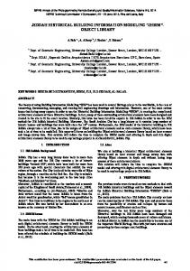
Figure 1. The LonMaker as a tool for development and integration of LonWorks networks
1. Introduction Existing tools for development of LonWorks building automation networks allow fast and easy planning of systems with up to 32,000 nodes. Network development is divided in two parts: determining the applications by connections between the nodes at the application layer and planning the architecture of the network by dimensioning the channels and connecting them to devices. Figure 1 shows a part of the LonMaker that is a common tool for the design of building automation systems [5]. The interdependency between application and physical layer and the impact from real processes are hard to overlook for the network designer. On the one hand bottlenecks and potential instabilities are not easily to identify, but on the other hand development needs to be fast and therefore does not allow detailed investigations of the future system behavior. However, careful performance evaluation is required to avoid overload in channels, long transaction times and unstable processes. Related work in the area of modeling fieldbus networks primarily deals with creation of models for simulation purposes [17], [15], [16]. Hintze et al. [3], [4] developed a method for performance evaluation of industrial fieldbus networks. Models were described in different languages (VHDL, UML, ESTELLE). After code gener-
ation the models were fed into simulation tools. Detailed knowledge about the process, the internal device behavior, the hardware and even the software is essential for this approach. The model building is not supported by databases where structural design or device information are contained. All components of the entire system model require manual editing. This leads to a tremendous effort for evaluation of common LonWorks networks with several thousand nodes. Automatic model building can be found in adjacent disciplines as well. Woodside et al. [19] propose to include a performance prediction into a software design environment. Details about the structure of the system (program code) are used automatically without requiring additional effort for model building. It enables the software developer to continuously check performance properties during the design process. In this paper we present an approach to automatically develop models for LonWorks networks. The goal is to model a building automation system using knowledge from existing design databases (LNS Network Operating System by Echelon) for subsequent performance prediction. Data about the network (subnet, channel etc.), de-
vice properties (e. g. ability to measure temperature and humidity), connections (bindings) and message structure (size, payload, etc.) are contained in the LNS Network Operating System and standard device descriptions [5]. They are reused for model creation. The main problem is to extract implicitly contained information suited for integration and maintenance tasks from the LNS Network Operating System. They have to be transformed to an explicit model for further performance evaluation. Generating our system model does not require additional effort for adjusting the network elements and process features. Only information already existing in machine-readable form is deployed. Our approach enables the developer of a LonWorks building automation network to acquire a complete model without additional effort. The performance of the control network is analyzed based on this model. GUI device data base
LNS Network Operating System
LNS Extractor
(containing standard device description) with generic assumptions about connected processes and are instantiated and adjusted in the NetPlan modeler. Last, the application layer is mapped automatically on to the physical layer to obtain a model of the communication in the network. This model then provides all necessary information for later analysis. In the next subsections we present the model which is divided in three parts - physical, application and communication model. The unified modeling language (UML) is used for description to enable better understanding and easy transformation to software. 2.1. Physical Layer Model The physical layer comprises all devices (holding profiles), channels (connected to devices) and network elements which interconnect the channels (router, bridge, gateway).
device data base
model data base
Network
Domain 1
join PHY and APP
1..*
Subnet 1
1..255
1
1..127 Neuron Element
deduce paket model
1 1..* Channel 1 1
Gateway
NetPlan modeler
1
Router 1
Bridge 1
Device 1
NeuronPort 1 2..* 2..* 2..*
Figure 2. General approach description Figure 3. Physical structure
In the next section we present our general model description for the application 1 layer and the physical 2 layer. Merging both layers leads to the communication model. In the third section the transformation to the queuing model is addressed followed by the modeling of an example network in section four.
Our model of the physical layer is shown in Figure 3. NeuronElement is an abstract base class for all elements in the network which have a NeuronC [11] chip inside. Four classes inherit from NeuronElement: Device (contains profiles with NetworkVariables for applications), Bridge (connects two channels within one subnet), Router (connects two channels in different subnets) and Gateway (connects to other Domains). Because the connection to other domains are not realizable with the LonMaker tool and the underlying LNS Network Operating System we neglect gateways in further investigations. A NeuronElement is connected via a NeuronPort to a distinct Channel. It is comparable with a plug from a channel to an element with a NeuronC chip. Hence, multiport devices like routers, bridges and gateways are associated to several NeuronPorts. LonWorks domains are divided into subnets. Each subnet contains dedicated channels. This relation is shown in Figure 3 by the aggregation of Channels in a Subnet. Hence, all NeuronElements are assigned to a subnet as well. Additionally, the class Binding hosts information about the service type used. Several service types are available in LonWorks networks: unacknowledged, acknowledged, repeated, authenticated and request/response. Detailed information about service types can be found in [11]. All information necessary to build up this model is contained by the LNS Network Operating System. We auto-
2. Extracting from Implicit Model The objective of our approach is to model a LonWorks network for analysis purposes. In Figure 2 the major steps which need to be taken are shown. First, the physical and application layer structures in the LNS Network Operating System are analyzed and the information necessary for modeling is gathered by our LNS Extractor. The gained specification is saved in the model database which is an intermediate database. Not only the model but also results obtained by later analysis are stored therein. Second, information about device types and positions are joined with device templates from the device database (similar to [9], [13]). It was developed for our modeling approach and is a collection of configured device templates. They are automatically generated from XIF-files 1 For simplification we understand the application layer in our work as all mechanisms above the network layer. It comprises all items which a LonWorks developer has to configure for an application. 2 All concrete artifacts in the network are considered as physical layer in this work.
2
matically read the entire structure of the network (domain, subnet, channels with bit rate, devices with transceivers) from this database and generate the model as mentioned above.
ing addressing in LonWorks networks [11]. Only one network variable can be the source address of a binding (has source in Figure 5). If unicast is used a second network variable has to be defined as the destination address. Other possible destination addresses are: multicast to groups, broadcast in subnets or domains. During usual operation unicast to network variables and multicast to groups is needed. Only configuration and management actions require broadcasting to subnets or domains. Again, the data required for building the application layer model (binding; source and destination address; profiles with network variables; variable types) either come from the LNS Network Operating System or from the device database. They are contained implicitly in this database. We extract them automatically to generate the model like mentioned above. With the association from NetworkVariable to Device we hold a connection from the physical layer to the application layer. However, the impact from the application layer to the physical layer and possibly vice versa is not known and will be the subject in the next subsection.
2.2. Application Layer Model Applications in LonWorks networks are assembled by connections (bindings) between NetworkVariables which are contained in standardized profiles [10]. The network developer uses software tools for establishing these bindings (see Figure 1). For our modeling approach templates from the device database are instantiated and configured. A template consists of generic devices which host generic network variables (similar to profile in Figure 4). If the net-
2.3. Deriving the Communication Model After modeling the application and physical layer in the NetPlan modeler, the information is mapped to derive a communication model. The aim of this mapping is to determine the impact of the behavior at the application layer to the packets actually sent with certain arrival rates and sizes at the physical layer. So far, the only connection between the layers is the association of the network variable to a distinct device. Hence, the network variable which is a source for a binding is taken as a starting point for the packet transmission. With the knowledge about the destination of the binding the way of the packet through the entire network is determined. Therefor, we apply tree searching through the physical structure [13]. Depending on the type of the addressing it can be one certain way, several ways, regions of the network or the entire network. Subsequently, the service type of the binding has to be evaluated. If, for instance, a message from the sender to the receiver requires an acknowledgment this has to be taken into account by a flow in the opposite direction. The classes which are to instantiate for the communication model are presented in Figure 6. Modeling the communication behavior means to derive the appropriate Communications for each Binding. An instance of Binding has one or more instances of Communication associated (dissects in in Figure 6). In an instance of Communication all information about one packet transfer from a sender to a receiver is held. It starts with the device where the source network variable is located. Subsequently, all elements which are passed by the packet are collected in a list in Communication. Apart from the way of the packet, the impact of the
Figure 4. Profile in a motor controller unit by WAREMA [18] work developer does not configure the instantiated devices we assume a standard process behavior. To obtain a more precise model additional information about the controlled processes is necessary. The NetPlan modeler enables the network developer to readjust the corresponding parameters. The process behavior is represented by variables which specify minimum, mean and maximum arrival rates. Previous work dealt with the underlying sendOnDelta concept [13], [12] and measurements for characterizing processes [6]. It is not necessary to provide detailed information about the hardware or the software running on the devices. A specification from the manufacturer of the device (generated for the mandatory XIF-file anyway) is sufficient to generate a device model. This saves effort for the network developer, since no further research for parameters which can not be found in the specification is needed. is destination 0..*
Domain
0..* 0..* is destination 1 has source
0..* 0..*
0..*
Binding 0..*
is destination 0..* is destination 0..*
hosts
Network Variable 1..*
Subnet Group 1 1..*
1 Device
Member
Figure 5. Application structure Figure 5 presents the dependencies of a binding within our model. The class Binding has associations represent3
is destination 0..*
Domain
is destination 0..*
Subnet
0..1
Table 1. Mapping from the UML model to a queuing analysis model
0..* Network Variable
0..* is destination 1 has source
1..*
0..* 0..*
0..*
Binding 1
0..*
is destination 0..*
dissects in 1
device
0..*
Bridge
0..*
goes across
Router
0..*
goes across
Gateway
0..*
goes across
0..*
goes across
Channel NeuronPort
starts at ends at
Group
UML Model Name → Queuing Model Communication → Message class NeuronPort → Queue Router → Additional delay station Channel → Load dependent station
1 1..* Member
0..* 0..* 1..* 0..* Communication 0..* floods 0..* 0..* 0..*
vice class is specified in the databases we use a finite capacity queue. Otherwise the queue capacity is assumed to be infinite. Further, it takes about 3ms for the router to process a message. Therefore, a router is described by a delay station. A channel is modeled as a load dependent service station with a varying service rate as a result of the protocol behavior. Table 1 summarizes these mapping rules. The mapping can be performed completely automatic based on the network model introduced before. The few additional properties that are required in addition like queue capacity of devices or delay times of routers can be easily replaced by default values or ignored completely without rendering the analysis impossible. Buchholz [1] gives more detail in analyzing a p-predictive CSMA network like the present LonWorks network with queuing theory.
goes across
mapping from APP to PHY
Figure 6. UML model for mapping from the application layer to the physical layer
service type of the binding needs to be ascertained. The number and size of packets which are exchanged between the sender and the receiver have to be identified. If a message requests an acknowledgment, the original way of the packet is duplicated with inverse order of the passed elements. The resulting instances of Communication determine the two messages sent from sender to receiver and vice versa. Analyzing all bindings in the same way leads to a model of the communication behavior. Together with the arrival rates in Binding the model will be analyzed according to load and transaction times of packets. Characteristics of the Communication instances (service type, pay load structure, retry counter, retry timer, arrival rate) are contained in the LNS Network Operating System and in the device database. We automatically read these information to derive a complete communication model.
4. Case Study with Example Network In the last part we want to present a case study with an example LonWorks network. Processing network specification from the intermediate model database into the NetPlan modeler should be verified. We presume an existing device database and that the network was read into the model database by the LNS Extractor. Figure 7 shows the physical structure of our example network. It consists of 7 subnets with 13 channels. There are 25 devices (12 senders, 13 receivers), 6 two-port routers and 6 two-port bridges connected to the channels. Due to complexity the application layer dependencies are not shown in Figure 7. However, there are 32 bindings in the network using all available service types and addressing possibilities. In our network example devices are used. The device database holds the generic templates necessary for the model. NeuronPort instances which are printed in bold in Figure 7 mark the near side ports of the routers. This implies that it is the dedicated router of the subnet where its near side port is connected to. A router only has one such port, all others are far side ports. From the subnet they are seen as ordinary devices. After reading from the model database and merging with the device information, a complete model of our example network is generated. Our NetPlan modeler then presents the network in a tree-like structure to the user for access.
3. Analysis with Queuing Networks If a model of a control network is generated it has to be analyzed according to the performance properties. In this section we give an example for the mapping from the afore mentioned model to a queuing analysis model [7], [8]. This allows performance prediction of the control network. The queuing network we propose uses multiple message classes with a specific size. These message classes can be derived from the communications (Subsection 2.3). The arrival rate of each message class is derived separately [14]. Every communication contains a list of the elements the message passes in the physical network. These elements which are channels and ports need to be transformed into the queuing model. A port can either belong to a device or a router. Both buffer messages if the channel is busy and therefore each port is mapped as a FIFO queue. If an entry for the queue length of a device or de4
Subnet 1 Sender 1
Receiver 1
Receiver 2
Sender 2
1.1.2
1.1.3
1.1.5
1.1.6
NE 1
NE 2
NE 3
NE 5
NE 6
NP 1
NP 2
NP 3
NP 6
Channel 1 NP 8 Sender 4
Receiver 4 1.2.2
1.2.1
Router 1
NE 12
NE 11
NE 9
NE 8
NE 7
NP 11
Channel 4
NP 5
NP 10
NE 4 Bridge 1
NP 12
1.5.1
1.5.2
NE 18
NE 19
NE 20
NP 25
NP 24
NP 26
Channel 7 NP 20
NP 27
Subnet 4 Receiver 7
NE 10 Bridge 2
Receiver 8
Router 4
NP 9
Channel 3 NP 13
Subnet 5
NP 23 Sender 6
1.2.4
NP 14
NP 4
Sender 3
1.2.5
NP 15
NP 7
Channel 2
Subnet 2 Receiver 5
Receiver 3
1.1.1
Sender 7
Subnet 6
Receiver 9
Receiver 10
Sender 8
Router 3
1.4.1
1.6.1
1.6.2
Router 5
1.6.4
1.6.5
NE 16
NE 17
NE 22
NE 23
NE 21
NE 25
NE 26
NP 16 Receiver 6
Sender 5
Router 2
1.3.2
1.3.1
NE 13
NE 15
NE 14
NP 21
NP 22
NP 29
Channel 6
NP 30
Channel 5
NP 19
NP 18
Receiver 12
Sender 11
Sender 10
NP 35 Receiver 11
NP 34
NP 33 Channel 9
Subnet 7 NP 17
NP 28
Channel 8 NP 31
NP 32
Sender 9
Sender 12
1.7.7
1.7.6
1.7.4
1.7.3
1.7.1
Router 6
NE 34
NE 33
NE 31
NE 30
NE 28
NE 27
NE 24 Bridge 3
Receiver 13
1.7.9
1.7.10
NE 36
NE 37
Subnet 3 NP 45
NP 44
NP 41
Channel 12
NP 40
NP 37
Channel 11 NP 43
NP 42
NE 32 Bridge 5
NP 36
NP 48
Channel 10
NP 39
NP 38
NE 29 Bridge 4
NP 49
Channel 13 NP 46
NP 47
NE 35 Bridge 6
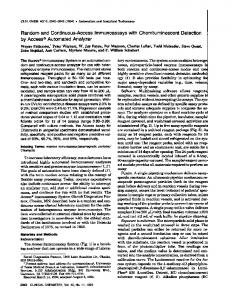
Figure 7. Example network fied by changing the corresponding parameters in the instance of a generic device. Therewith, different models are available, even configurations for special scenarios (e.g. critical process behavior or emergency situations) are realizable.
5. Summary In this paper we presented an approach for automatic modeling of LonWorks networks. With the LNS Network Operating System and a device database we are able to generate a system model. It is divided in three parts: the physical layer model, the application layer model and the derived communication model. Only little additional effort is necessary to create this representation of the building automation system as a basis for later performance prediction. Thus, developers of such systems are enabled to evaluate the design with respect to performance properties. Models are to render more precisely by additional information about the environmental process. Therewith, more accurate estimations are to achieve. Using an example network we demonstrated the feasibility of our approach. It is possible to read a structure from the model database, join it with information about the devices and deduce a communication model. We automatically calculated the accumulated arrival rate in the channels and deduced bottlenecks in the example network. The availability of better device models (more detailed XIF-files) and estimations about the processes improve our results. Developing a connection to existing data sets about devices [9] are conceivable but require further investigation. The method is applicable where certain design information about control networks are available in machine-
Figure 8. Load estimation for the example network
Subsequently, the generated model is analyzed according to the accumulated arrival rate in the channels. It means that the arrival rate which is produced by all devices connected to the same channel is summed up. This allows an estimation of potentially overloaded network sections. Figure 8 shows the results of this estimation for the example LonWorks network in our NetPlan modeler. From these channel load calculations simple conclusions about the devices connected to the same channel are drawn. Heavy load sources can be identified easily. For the second analysis step the model is analyzed using performance evaluation methods and tools [7]. More detailed information about the building automation system (e. g. transaction times, retransmission induced load) is gained from this analysis. Even predictions of the stability of the plant are possible [6]. If required, the resulting model can be adjusted by the LonWorks network developer. Process models are modi5
readable form. Beside the presented approach for LonWorks networks the method is applicable i. e. for EIB based networks. Using the DCOM library Falcon for access to the design platform ETS3 [2] enables extraction of the neccessary information about the network. Additional information about processes and devices improve the accuracy of the model and subsequent analysis results. In contrast to other approaches for modeling fieldbus systems ([17], [3], [4]) we are able to extract all information from a database existing anyway. Therewith, no additional effort for model description and parameterization is neccessary. Subsequently, the performance evaluation with analytic methods [1] is done. Further work will be on testing with real networks. We also want to develop a module which automatically configures the process behavior according to predetermined scenarios.
[12] M. Neugebauer and K. Kabitzsch. A New Protocol for a Low Power Sensor Network. In H. Hassanein, R. L. Oliver, G. G. R. III, and L. F. Wilson, editors, Proceedings of the 23rd IEEE International Performance, Computing and Communications Conference (IPCCC 2004), pages 393–399, Phoenix, Arizona, April 2004. IEEE. [13] M. Neugebauer, J. Pl¨onnigs, and K. Kabitzsch. Prediction of Network Load in Building Automation. In 5th IFAC International Conference on Fielbus Systems and Their Applications (FeT 2003), Aveiro, Portugal, 2003. [14] J. Pl¨onnigs, M. Neugebauer, and K. Kabitzsch. A Traffic Model for Networked Devices in the Building Automation. In Proceedings of the 5th IEEE International Workshop on Factory Communication Systems (WFCS 2004), Vienna, Sept. 2004. to appear. [15] P. Schwarz and U. Donath. Simulation-based Performance Analysis of Distributed Systems. In International Workshop Parallel and Distributed Real-Time Systems, pages 244–249, Geneva, Switzerland, 1997. [16] Stefan R¨uping and Ralf Hunstock and Uwe Gunreben. Simulation of LonWorks Systems. In Proc. of the LonUsers International Fall 97 Conference, 1997. [17] T. Tomura, K. Uehiro, S. Kanai, and S. Yamamoto. Developing Simulation Models of Open Distributed Control System by Using Object-Oriented Structual and Behavioral Patterns. In Fourth IEEE International Symposium on Object-Oriented Real-Time Distributed Computing, pages 428–437, Magdeburg, Germany, May 2001. [18] WAREMA Renkhoff GmbH. WAREMA LonWorksSteuerungen. Marktheidenfeld, 2003. [19] M. Woodside, C. Hrischuk, B. Selic, and S. Bayarov. A wideband approach to integrating performance prediction into a software design environment. In Proceedings of the First International Workshop on Software and Performance, pages 31–41, New York, NY, USA, 1998. ACM Press.
6. Acknowledgment The project the present report is based on was promoted by the Federal Ministry of Education and Research under the registration number 13N8177. The authors bear all the responsibility for contents.
References [1] P. Buchholz. Analytical analysis of access-schemes of the CSMA-type. In Proceedings of the 5th International Workshop on Factory Communication Systems (WFCS 2004), Vienna, Austria, September 2004. [2] EIB Association, 2004. www.eiba.com. [3] E. Hintze. Modellierung und Simulation heterogener, industrieller Kommunikationsnetzwerke. In Entwurf komplexer Automatisierungssysteme - EKA 2003, pages 175– 193, Braunschweig, Juni 2003. [4] E. Hintze and P. Kucera. Simulation of RFieldbus Networks. In Proceedings of the 5th IFAC International Conference on Fielbus Systems and Their Applications (FeT 2003), pages 115–122, Aveiro, Portugal, July 2003. [5] K. Kabitzsch, D. Dietrich, and G. Pratl, editors. LonWorks - Gewerke¨ubergreifende Systeme. VDE Verlag GmbH, Berlin, 2002. [6] K. Kabitzsch and M. Neugebauer, editors. Netzwerke in der Geb¨audeautomation - Modellierung, Voraussage, Planung, Dresden, 2003. ISBN 3-86005-409-0. [7] K. Kant. Introduction to computer system performance evaluation. McGraw-Hill, New York [et al.], 1992. [8] L. Kleinrock. Queueing Systems, vol I & II. A WileyInterscience publication. Wiley, New York [et al.], 1975. [9] LON Nutzer Organisation e. V. Datenbank der LON Nutzer Organisation e. V. visited February 2004, www.lno-db.de. [10] LonMark Interoperability Association, 2004. www.lonmark.org. [11] D. Loy, D. Dietrich, and H. Schweinzer, editors. Open Control Networks. Kluwer Academic Publishers, Boston, Dordrecht, London, 2001.
6