AUTOMATED PERFORMANCE OPTIMISATION AND LAYOUT SYNTHESIS OF MEMS ACCELEROMETER WITH SIGMA-DELTA FORCE-FEEDBACK CONTROL LOOP Chenxu Zhao and Tom J. Kazmierski School of Electronics and Computer Science University of Southampton, UK cz05r,
[email protected] Abstract This contribution presents a novel methodology for automated optimal design of a MEMS accelerometer with Sigma-Delta force-feedback control loop from user defined high-level performance specifications and design constraints. The proposed approach is based on a simulationbased optimization technology using a genetic algorithm. The layout of the mechanical sensing element is generated simultaneously with the optimal design parameters of the Sigma-Delta control loop. As currently available implementations of AMS HDL languages are not suitable for complex mixed-technology system optimisation, the algorithm as well as aa fast dedicated sigma-delta accelerometer simulator have been implemented in C++. The underlying accelerometer model includes the sense finger dynamics described by a partial differential equation, which enables accurate performance prediction of the sensing element embedded in a in mixed-technology control loop.
1. Introduction Usually, MEMS accelerometer design requires a significant amount of specialist human resources and time in the iterative trial-and-error design process to determine the crucial trade-offs in meeting the performance specifications. Some methodologies have proposed an automated approach to MEMS accelerometer synthesis [1] [2] [3] [4] where the design requirements are formulated as a numerical nonlinear constrained optimization problem, and solved with powerful optimization techniques. However, these approaches are constrained to open-loop or analogue feedback loop accelerometer design. Our goal is not only to automate the layout generation of the mechanical sensing element but also to obtain optimal system-level parameters in the Sigma-Delta force feedback control loop. In particular, our design methodology uses accurate modelling of the sense
finger dynamics and a simulation-based optimization to improve the performance of a system-level digital accelerometer. Our approach is hollistic in the sense that the optimal design parameters and geometrical layout of the mechanical sensing element based are generated simultaneously. Due to their relatively high resolution and low temperature sensitivity, capacitive accelerometers are widely used in various industrial applications. The commonly used lateral capacitive sensing element topology [5] [6] has been selected for this project and its layout and properties are discussed in the next section. High-performance MEMS usually employ an electromechanical Sigma-Delta modulation feedback control to improve the performance and, in particular, to obtain a wider bandwidth, a larger dynamic range and also to convert the acceleration signals directly to a bit stream suitable for further digital processing [7] [8] [9] [10] [11]. It has been observed that the sense finger resonance, usually not included in standard models, affects the performance of the electromechanical Sigma-Delta feedback loop [12]. The conventional approach normally applied in simulations of such systems, where a 2nd order lumped Mass-Damper-Spring equation is used to model the mechanical sensing element, cannot capture the effect of the sense finger dynamics. In this contribution a distributed approach, where the sense fingers are modelled as cantilever beams whose motion can be described by Partial Differential Equations(PDEs), has been applied to reflect the effects of the sense finger dynamics.
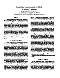
2. Mixed-technology model of the system A block diagram of the entire system is shown in Figure 1 and the layout of mechanical sensing element is shown in Figure 2. In the sensing element, the proof mass is suspended by two springs and it is equipped with sense and force comb fingers which are placed between fixed fingers
to form a capacitive bridge. Such constructed mechanical sensing element can detect a differential change in the capacitance, which is caused by the displacement of sense fingers, and convert it to voltage (Vout). The electrostatic force acting on the force fingers is used as the feedback signal to pull the proof mass in the desired direction. Vf 1 and Vf 2 are the feedback voltages obtained from the DAC and Vm (t) is a high frequency modulation voltage: Vm (t) = VmA sin(2πfm t)
(1)
where VmA is the amplitude voltage and fm is the modulation frequency. The lead compensator is required to ensure the stability of the control loop. A clocked 1-bit quantizer is used for oversampling and generating a pulsedensity modulated digital output signal.
where f (t) represents the input and feedback forces, M is the the proof mass, x is the deflection of the proof-mass, D and K are the damping coefficient and spring constant respectively. In reality however, the sense element fingers may vibrate due to their own dynamics, thus rendering the feedback excitation ineffective, causing an incorrect output and a failure of the system [12]. This scenario cannot be reflected by the conventional model given by equation (2). A more accurate, distributed mechanical sensing element model, which can exhibit higher resonant frequencies, is illustrated in Figure 3 where the electrostatic force acts along the length of the finger beam. C1 and C2 are the total distributed differential capacitances between the beam and the electrodes.
Input force Fin(t)
Damper
Sampling frequency fs
+Vm(t)
Mechanical sensing element
-Vm(t)
Continuous Lead Compensator
Buffer
Spring
+Vm(t)
Output bitstream
C1 Proof mass
Quantizer
Sense finger C2
Vf1 Vf
Fixed electrode
Feedback force -Vm(t)
Vf2 1-bit DAC
Vf
Figure 3. Sensing element distributed model.
Figure 1. Electromechanical Sigma-Delta accelerometer
Spring
The motion of the beam can be modelled by the following partial differential equation (PDE):
Anchor Force finger
Vf1
Vf1 Vf2
Vf2
+Vm(t)
+Vm(t)
-Vm(t) Vf1 Vf2
-Vm(t) Vf1 Vf2 Sense finger
Proof mass Vout
Conventionally, the mechanical sensing element in figure 1 is a mass-damper-spring system modelled by a 2nd order differential equation: dx d2 x +D + Kx 2 dt dt
2 2 1 VmA VmA εLf T [ − ] 2 (d0 − y(x, t))2 (d0 + y(x, t))2 (4) where ε is the permittivity, Lf is the length of sense finger and d0 is the initial gap between sense finger and fixed electrodes. The root ends of the sense fingers move with the lumped proof mass whose deflection could be modelled by the 2nd
Fe (x, t) =
Figure 2. Lateral capacitive sensing element
f (t) = M
∂ 2 y(x, t) ∂ 5 y(x, t) ∂ 4 y(x, t) + CD I + EI = Fe (x, t) 2 4 ∂t ∂x ∂t ∂x4 (3) where y(x, t) , a function of time and position, represents the beam deflection, E, I, Cd , ρ, A are physical properties of the beam: ρ is the material density, A is the cross sectional area (Wf ∗ T , where Wf and T are width and thickness of the beam), E is Young’s modulus and I is the second moment of area which could be calculated as I = T Wf3 /12 and Cd is the internal damping modulus. The product EI is usually regarded as the stiffness . Fe (x, t) is the distributed electrostatic force along the beam: ρA
(2)
order differential equation similar to equation (2): M
d2 z(t) dz(t) +D + Kz(t) = Ff (t) + Fin (t) 2 dt dt
(5)
The total distributed sense capacitance between the sense fingers and electrodes is: Z
Lf
C1 (t) = Ns εT 0
Z
Lf
C2 (t) = Ns εT 0
1 dx d0 − y(x, t)
(6)
1 dx d0 + y(x, t)
(7)
Where Ns is the number of sense fingers. The output voltage can be calculated as: Vout (t) =
C1 − C2 Vm (t) C1 + C2
(8)
Like in the conventional model, the lower resonant mode is caused by the dynamics of the structure mass, when the sense finger and lumped mass move ptogether. The resonant frequency is approximately ω0 = K/M where the K is the suspension spring constant and M is the total mass of the lumped mass and sense fingers. The higher resonant mode is related to the sense finger resonance. If it occurs, the fingers bend significantly while the lumped mass has a small deflection.
3. Performance optimisation algorithm and experimental results The proposed automated design approach explores the design according to user defined specifications and optimises the structural parameters of the sensing element and the Sigma-Delta control loop parameters. The design variables are listed in table 1. For the mechanical sensing element, proof mass, comb fingers and springs have the same thickness(T). The numbers of sense(Ns) and force(Nf) rotor fingers represent the structural parameters.
3.1 Initial design The initial design parameters are shown in table 2. The sense finger resonance may affect the performance of the Sigma-Delta control loop as fingers might bend significantly. The first two resonant frequencies could be calculated as those of the cantilever beam [12] : s E 2 Wf α1 = 1.875, α2 = 4.694 (9) ωi = αi 2 Lf 12ρ Here we perform parameter sweeps to analyze the effect of the sense finger resonance. Figure 5 shows the result of sweeping the length of sense finger from 100um to
Design Variables of sensing element Wpm Width of proof mass Lpm Length of proof mass Ls Length of spring Ws Width of spring Lf Length of fingers Wf Width of fingers d0 Initial gap T Thickness of sensing element Structural parameters Ns Number of sense fingers Nf Number of force fingers Sigma-Delta control loop parameters VmA Amplitude of modulation voltage ZERO Zero of lead compensator POLE Pole of lead compensator Vf Feedback force voltage
range 50um-150um 300um-700um 200um-300um 1um-5um 50um-200um 0.8um-2um 1um-3um 2um-8um range 10-30 5-20 range 1V-5V 0.01-10 100-20000 1V-10V
Table 1. Parameters of Sigma-Delta accelerometer
230um. SNR changes with the length of fingers and a failure of the Σ∆ control loop is captured when the length is above 210um. Figure 4 presents the power spectral density (PSD) of the output bitstream. However, this effect cannot be captured in conventional model.
3.2 Optimization algorithm The automated optimal design process is shown in figure 6. Genetic algorithm is used in combination with a dedicated behavioral MEMS accelerometer model to optimise the objective function which in these experiments is selected to either maximize the signal to noise ration (SNR) or the static sensitivity. The input specifications are the geometrical constraints of the sensing element, control loop parameter ranges and performance specifications. The algorithm generates an optimized layout of the sensing element and parameters of the Σ∆control loop.
3.3 Fitness Function and experimental results The proposed approach is demonstrated by two experiments. In Experiment 1 the fitness function (optimisation goal) is to maximise the SNR, and in Experiment 2 - the static sensitivity. In both experiments the input performance constraints are: 1) Signal-to-noise ratio: SNR>30dB
INPUT specifications Design Variables Initialization New generation Genes for whole population
(a) Power spectrum density of output bitstream (sense finger length=120um)
Mutation
System Simulation
Crossover
Performance Evaluation (Fitness Function)
Selection
No
Genetic Algorithm Optimization Loop
Max Generation reach Yes
Final Optimized design & Layout of sensing element
Figure 6. Synthesis process of proposed approach (b) Power spectrum density of output bitstream (sense finger length=210um)
2)Static sensitivity of mechanical sensing element: S>1.5fF/g
Figure 4. Power spectrum density analysis ∆C = C0 (
d0 d0 − ) d0 − ∆X d0 + ∆X
(11)
εT Lf (12) d0 Where C0 is the static capacitance and ∆X is the displacement of the sense fingers when applying 1g (1g = 9.8m/s2 ) acceleration. The search for a solution is guided by an optimization objective. The objective fitness function is in the following format: Objective Ff it = K ∗ (13) Objectiver where K is a constant whose value depends on whether the performance constraints are met. K is set to 100 if these constraints both are met, otherwise K is 0.01. Objective is static sensitivity or SNR obtained from each simulation while Objectiver are the user defined reference value. SN Rr and Sr are the reference SNR and static sensitivity got from user defined constraints. C0 = Ns
Figure 5. Resonance of sense fingers affect the performance of Σ∆ loop. Σ∆ control loop failure is captured when the sense finger length exceeds 210um
It is the ratio of the total power in the signal bins to the total power in the noise bins [13]: SN R =
P wsignal P wnoise
(10)
where P wsignal and P wnoise are the signal and noise power in band respectively.
Experiment 1 : maximum SNR Fitness functions: Ff itSN R = K ∗
SN R SN Rr
(14)
where the reference SNR: SN Rr = 30dB
(15)
Experiment 2 : maximum static sensitivity Fitness functions: Ff itS = K ∗
S Sr
(16)
where the reference static sensitivity: Sr = 1.5f F/g
(17)
There are many crucial trade-offs in the MEMS accelerometer design. For example, static sensitivity is dependent on the length and number of the sense fingers. However, the performance of sigma-delta modulation may be severely affected by the length of sense fingers to the extent that a complete failure of the sigma-delta control may occur when the fingers are too long. The maximum number of fingers is also limited by the length of proof mass. To maintain the same resonant frequency, the finger width should be reduced if the length of the proof mass increases. This results in a sensitivity decrease. The presented optimization-based approach deals with these trade-offs effectively for a given choice of the design objectives.
4. Conclusion This paper presents an effective simulation-based approach for synthesis of MEMS accelerometer in SigmaDelta control loop. Due to the complex nature of the optimisation process, the algorithm has been implemented in C++ to overcome limitations of the available AMS HDL tools. While these tools are extremely well suited for complex modelling, implementation of post-processing of simulation results and optimisation algortihms is difficult. Future work will extend the digital MEMS accelerometer design to multi-objective optimisation and an automated synthesis of the control loop where higher order Sigma-Delta systems will be used to maximise the performance.
(a) Experiment 1: maximum SNR
References [1] T. Mukherjee, Y. Zhou, and G.K. Fedder. Automated optimal synthesis of microaccelerometers. Micro Electro Mechanical Systems,, pages 326–331, 1999. [2] Gary K.Fedder, Sitaraman Iyer, and Tamal Mukherjee. Automated optimal synthesis of microresonator. Solid State Sensors and Actuators,, pages 1109–1112 vol.2, 1997.
(b) Experiment 2: maximum static sensitivity
Figure 7. Fitness improvement Optimizations were carried out using the following design parameters: 1) Oversampling ratio: OSR=64 2) Sampling frequency: fs =1MHz 3) Input force: Fin (t) = FAmp sin(2πfinput t)
(18)
where FAmp =100g*M (1g = 9.8m/s2 ) and finput =2KHz. The fitness functions for both experiments are shown in figure 7 and optimisation results in table 2. As expected, the structure optimised for maximum sensitivity has more and longer sense fingers. The layout of the mechanical sensing element, which is also generated by the system, is shown in figure 8.
[3] Zhun Fan, Erik D.Goodman, Jiachuan Wang, Ronald RosenBerg, KisungSeo, and Jianjun Hu. Hierarchical evolutionary synthesis of MEMS. Evolutionary Computation,, pages 2320– 2327 Vol.2, 2004. [4] V. Gupta and T. Mukherjee. Layout synthesis of CMOS MEMS accelerometers. MSM 2000, pages 150 – 153, ISBN: 0–9666135–7–0, 2000. [5] Analog Device. Adxl150/adxl250 data sheet. Datasheet, Norwood, MA 02062-9106, 1998. [6] M. Lemkin and B.E. Boser. A micromachined fully differential lateral accelerometer. Custom Integrated Circuits Conference,, pages 315–318, 1996. [7] Yufeng Dong, Michael Kraft, Carsten Gollasch, and William Redman-White. A high-performance accelerometer with a fifth-order sigma-delta modulator. Journal of Micromechanics and Microengineering, 15:S22–S29, 2005.
Design Variables
Initial Design
SNR optimized Design
Design Variables
Initial Design
6um 136um 468um 300um 2um 130um 1.85um
Static sensitivity optimized design 7.93um 148.6um 641.2um 298.6um 1um 186.7um 1.85um
T Wpm Lpm Ls Ws Lf Wf Device Parameters Spring constant Mass Static sensitivity Fr
SNR optimized Design
1um 30 20 4V 3.4 777 4V
Static sensitivity optimized design 1um 30 18 2.5V 4.26 1.69e+4 5V
7.66um 91um 433.6um 267um 1.38um 107.15um 1.3um
0.881N/M
0.177N/M
0.511N/M
0.899ug 3.84fF/g
1.76ug 72fF/g
0.7046ug 5.65fF/g
d0 Ns Nf Vm ZERO POLE Vf Device Parameters Damping coefficient SNR Static capacitance
45.7 uN(m/s) 34.95dB 207fF
142.5 uN(m/s) 30.4dB 393fF
69.27 uN(m/s) 42.9dB 189fF
5KHz
1.6KHz
4.29KHz
1um 26 12 3.7V 1.0 597 5.4V
Table 2. Automated optimized design results
(a) Initial Design SNR=34.95dB Static Sensitivity=3.84fF/g
(b) Optimization design of experiment 1 (Static sensitivity optimized design) SNR=30.4dBdB Static Sensitivity=72fF/g
(c) Optimization design of experiment 2 (SNR optimized design) SNR=42.9dBdB Static Sensitivity=5.65fF/g
Figure 8. Synthesized layouts. Comparing with SNR optimized design, sensitivity optimized design contains more and longer fingers.
[8] M. Kraft, C.P. Lewis, T.G. Hesketh, and S Szymkowiak. A novel micromachined accelerometer capacitive interface. Sensors & Actuators, A68/1-3:466–473, 1998.
digital accelerometer in simulink and pspice. Control ’96, UKACC International Conference on (Conf. Publ. No. 427), vol.1:205– 209 vol.1, 1996.
[9] M. Kraft, C.P. Lewis, and T.G. Hesketh. Closed loop silicon accelerometers. IEE Proc. - Circuits, Devices Syst.,, 145:325–331, 1998.
[12] J.I. Seeger, J. Xuesong, M. Kraft, and B.E. Boser. Sense finger dynamics in a Σ∆ force feedback gyroscope. Tech. Digest of Solid State Sensor and Actuator Workshop, pages 296–299, Jun 2000.
[10] M. Kraft, W Redman-White, and M.E. Mokhtari. Closed loop micromachined sensors with higher order Σ∆modulators. Proc. 4rd Conf. on Modeling and Simulation of Microsystems, pages 104–107, 2001. [11] C.P. Lewis and M. Kraft. Simulation of a micromachined
[13] Steven R. Norsworthy, Richard Schreier, and Gabor C. Temes. Delta-Sigma Data Converters: Theory, Design, and Simulation. John Wiley and Sons. Inc, Hoboken, New Jersey, USA, 2005.