Automated Power Gating Methodology for Dataflow-Based Reconfigurable Systems Tiziana Fanni, Carlo Sau, Luigi Raffo
Francesca Palumbo
University of Cagliari Dept. of Electrical and Electronics Engineering Via Marengo 3, 09123 Cagliari, ITALY
University of Sassari PolComIng - Information Engineering Unit Viale Mancini 5, 07100 Sassari, ITALY
[email protected]
[email protected] ABSTRACT Modern embedded systems designers are required to implement efficient multi-functional applications, over portable platforms under strong energy and resources constraints. Automatic tools may help them in challenging such a complex scenario: to develop complex reconfigurable systems while reducing time-to-market. At the same time, automated methodologies can aid them to manage power consumption. Dataflow models of computation, thanks to their modularity, turned out to be extremely useful to these purposes. In this paper, we will demonstrate as they can be used to automatically achieve power management since the earliest stage of the design flow. In particular, we are focussing on the automation of power gating. The methodology has been evaluated on an image processing use case targeting an ASIC 90 nm CMOS technology.
Keywords Power gating, coarse-grained reconfigurable systems, dataflow, MPEG-RVC, automated power management
1.
INTRODUCTION
From portable consumer electronics to wearable medical devices, power reduction is one of the biggest challenges in modern systems development. Normally, it tends to collide with the need of embedding complex and fancy resourceintensive applications. Several effective techniques for power monitoring and reduction are available in literature, but very often their application is complex, error prone and time consuming. These issues limit their extensive use to application specific scenarios. In communication network design SONICS exploited many of the techniques used to manage power consumption (clock gating, power gating, voltage scaling etc.) for implementing an efficient power management strategy at the SoC level [16]. The same may apply to boost application performance, while preserving power efficiency. The ARM big.LITTLE processor, for example, implements
Permission to make digital or hard copies of all or part of this work for personal or classroom use is granted without fee provided that copies are not made or distributed for profit or commercial advantage and that copies bear this notice and the full citation on the first page. To copy otherwise, to republish, to post on servers or to redistribute to lists, requires prior specific permission and/or a fee. Computing Frontiers 2015 Ischia, Italy Copyright 2015 ACM 978-1-4503-3358-0/15/05 ...$15.00. http://dx.doi.org/10.1145/2742854.2747285
a power optimization technology: two sets of processors are available, but in the normal use cases, cores are never on at the same time [5]. To the best of our knowledge, to extend the adoption of energy management techniques efficient automated strategies are required. In this paper we are presenting a power management methodology for runtime reconfigurable multi-functional systems based on the MPEG Reconfigurable Video Coding dataflow standard. Our work exploits the Multi-Dataflow Composer (MDC) tool for the automatic generation of a reconfigurable coarse-grained hardware platform. Dataflow modularity allows us to use the high-level coarse-grained model of the system, produced by MDC, to extract the logic partitioning of the resources. This latter is then used to automatically derive a power gated system description. The proposed automated methodology has been tested, as a proof of concept, on an ASIC 90 nm CMOS technology and compared with another automatic power aware design flow [12]. Results revealed the potentiality of the proposed approach and gave us several hints for future optimizations. The rest of this paper is organized as follows. Section 2 defines the scientific context of this work. Section 3 describes the proposed power management approach. Section 4 discusses the achieved results, prior to conclude in Section 5.
2.
BACKGROUND
In this section we are going to present the scenario of the presented work (Sec. 2.1) along with the foundations of the power-management strategy we are proposing (Sec. 2.2).
2.1
The MPEG RVC-CAL Standard
A dataflow program is a directed graph where nodes represent computational units (actors), while edges represent loss-less, order-preserving point-to-point connections between actors, used to communicate sequences of data packets (tokens). In terms of notation, let’s define DF GhV, Ei as a directed graph, where V is the set of vertices of the graph (the actors) and E is the set of edges (the connections). Actors asynchronously concur to the computation and can be transformed either into software agents or physical Functional Units (FUs). The MPEG Reconfigurable Video Coding (RVC) standards ISO/IEC 23001-4 and 23002-4 adopt a Dataflow Process Network (DPN) model of computation with firing rules [7]. It refers to a subset of the more general CAL actor language [4]. This language directly captures the description of DPN actors. The evolution of the actors state is enabled by conditions on its current state and on the available input
tokens. Connections are implemented as FIFO channels. The MPEG-RVC research community has also developed a large set of tools composing a complete hardware software co-design environment [1, 2, 9]. However within MPEGRVC power-management has been just limitedly addressed.
2.1.1
The Multi-Dataflow Composer Toolchain
In this paper, we are going to exploit some recent studies in the MPEG-RVC field related to clock gating over reconfigurable platforms [12] and we are going to present how to extend them to provide also power gating. These studies are related to the Multi-Dataflow Composer (MDC) tool, which is a RVC-CAL compliant framework conceived for the automatic creation and management of multi-functional systems. It was meant to address the difficulty of mapping different applications onto a coarse-grained reconfigurable architecture [3, 6]. Its final goal [10, 11] is to automate such a mapping process while minimizing hardware resources, with consequent area/energy saving. To assemble the coarse-grained reconfigurable multi-functional system, MDC exploits the modularity offered by the dataflow models processing a set of input DPNs (representing the different functionalities to be implemented). To perform a single-cycle reconfiguration, MDC inserts in hardware low overhead switching modules (SBoxes) placed at the crossroads between the different paths of data. SBoxes programmability is maintained through a Configuration Map. MDC already embeds a power saving automatic feature [12]. In particular, it is able to analyse the input dataflow models and to extract from them the optimal actors partitioning in order to implement clock gating power management strategies. In this paper, we are going to improve such an approach extending the possibility of mapping all the hardware resources (including also the switching elements and not only computational actors) over different power domains, enabling automated power gating strategies.
2.2
Power Management
In the dark silicon era not all the available resources on a die are usable due to the limited power budget, thus power management strategies are extremely important. The more the integration on a single die the more holistic power minimization approaches are required across the design stack. Power consumption in digital systems consists of different contributions: dynamic and static. The former is due to capacitance charging/discharging when logic transitions occur (i.e. switching activity). The latter is due to leakage currents and it is consumed even when the circuit is not switching. Several power management techniques (clock gating, multi-frequency, multi-threshold, power gating...) exist, and in some cases they are automatically implemented by synthesizers. However, generally speaking, the more the technique is invasive (in terms of requested additional logic and target technology support1 ) the less it is automated. Clock gating (CG) is an example of quite non-invasive technique that consists in shutting off the clock of the unused synchronous logic. CG has been deeply automated and it is available on most of the commercial synthesizers. In the MPEG-RVC community, recent studies [2] presented an extension of an High-Level Synthesis tool, Xronos, to selectively switch off parts of the circuit that cannot execute. 1 Such as the availability of dedicated cells and processes on the implementation stack.
2.2.1
Power Gating Technique
Even though the dynamic contribution of the power has historically been significantly bigger than the static one, nowadays with the technology scaling static power consumption cannot be neglected anymore. Power saving techniques for static power management are typically more invasive. In this work we have extended the results of [12] with a coarse-grained approach to power gating (PG). This technique switches off the power supply of the design portions that are not involved in the current computation. We have developed a procedure to identify logic regions within a reconfigurable system, in order to define different power domains (PDs) to be alternatively activated. Our procedure acts at a high level of abstraction, thus resulting in architecture and technology aware features. In literature several works have explored the tradeoffs of adopting PG, presenting it as a promising technique for the future technology [8]. Very often the focus has been on the PG physical implementation optimization, sometimes developing automated flows to cluster and interface different PDs [14]. However, as far as we know, no automatic frameworks act at a higher level. PG requires to add, for each PD, the following resources: • the sleep transistor between the gated region and the power supply to switch on/off the power supply; • the isolation logic between the gated region and normallyon cells to avoid the transmission of spurious signals in input to the normally-on cells; • the state retention logic to maintain the internal state of the gated region. To the best of our knowledge, this additional logic can be manually inserted by the designers in the RTL architecture or through a power format file. Manual definition is highly error prone: it requires modelling the impact of low-power during simulation and providing multiple definitions for synthesis, placement, verification and equivalence checking [13]. On the contrary, the power format file allows designers specifying power saving techniques early in the design, relieving them from the direct modification of the RTL design. Nevertheless, the definition of a power format file is still error prone. To deal with 40 different PDs, you need to define the shut-off, isolation and state retention rules (3*40= 120 interfaces). Then for each rule its enables signals have to be created ([1*shut-off + 1*isol. + 2*reten.] * 40 = 160 signals). A dedicated power controller to properly drive these latter is also required. Therefore, as you can see, the manual definition of the power format file may easily turn out in a nightmare and, to the best of our knowledge, no tools are available to automatically write it. In this paper, to provide automation of power management, we have adopted the Silicon Integration Initiative’s Common Power Format (CPF), driven mainly by Cadence [15]. Our strategy allows the automatic definition of the power controller and the CPF for coarse-grained reconfigurable systems.
3.
AUTOMATED POWER GATING STRATEGY
In this section we are going to present the automated power management strategy, based on power gating, we have envisioned. First step of this strategy is the Logic Regions identification (Sec. 3.1). Then, it will be explained how,
starting from those regions, it is possible to automatically implement a power gated platform (Sec. 3.2).
3.1
Logic Regions Identification
In this section we present the strategy that we have developed to partition the reconfigurable system architecture basing on the dataflow intermediate output provided by MDC. The partition is meant to bound the dataflow actors, and in turn the respective hardware FUs, into disjointed Logic Regions (LRs). A LR identifies a set of resources that from the functional point of view are active/inactive together. Therefore, it is possible to enable/disable them at the same time, preserving the computing correctness. LRs, identified at design-time, are then exploited, at runtime, to implement power-management strategies. LRs identification is performed on the multi-functional dataflow assembled by MDC. It maps each set of actors Vi belonging the i-th input network DF Gi hVi , Ei i to a set of actors Vi0 ⊆ V , where DF GhV, Ei corresponds to the intermediate output multi-functional specification. In this paper, we need to include within the regions to be power gated also the combinatorial switching actors (SBoxes), which are not included in the analogue LRs identification performed by MDC [12] (in a clock gating perspective, they do not have any clock to be switched off), but they contribute to the static power consumption. In this implementation, the V set involves then the set of computational actors V 0 as well as the set of SBoxes V 00 (V = V 0 ∪ V 00 ). Considering S as the complete set of LRs, our aim is not only to find it as a partition of V , but also to minimize the number of elements, N , within S since the more the LRs to enable/disable, the more additional logic is needed to drive them. Moreover, S must also contain a partition of the set of actors Vi0 of each input network. In particular, this would mean that, when an input network is executed, exclusively its actors will be effectively active. The process keeps trace (M AP ) of the input DPNs associated to each LR Sj. LRs identification process is composed of two steps (see Algo. 1). During the first step, the LRs S related to the computational actors V 0 are identified by processing the multifunctional dataflow generated by MDC and the set of input dataflows. In the beginning M AP is empty, and the first Vi0 constitutes the first LR. For all the other iterations three different situations may occur: • Vi0 = Sj : M AP is updated, set Sj points the current DPN; • Vi0 ∩ Sj 6= ∅: a new LR, containing the intersected instances, is issued and the pre-determined set Sj and Vi0 are modified by removing the intersection. A new entry in M AP matches this new set with the current input DPN and all the DPNs already associated to Sj . • Vi0 6= ∅ (the current set is disjointed with respect to the previous ones): a new LR is pushed in M AP . At the end, the minimum number of LRs is identified. Then also the SBoxes V 00 are added to the partition S: if an input dataflow activates the SBox 2 , then it has to be operative when that functionality is requested. The following situations may occur: 2
The correspondent value within the Configuration Map (C M AP ) associated to the multi-functional dataflow is not a don’t care.
Algorithm 1: High-level two-step description of the Logic Regions identification (N = |M AP |). /* Computational Actors LRs identification */ foreach DP Ni in input DP N s do Vi0 =mapping of DP Ni in DP N ; if isEmpty(M AP ) then S0 = Vi0 ; put key S0 with value DP Ni in M AP ; else foreach Sj in M AP keys do if Vi0 = Sj then add DP Ni to value of key Sj in M AP ; break; end if Vi0 ∩ Sj 6= ∅ then SN = Vi0 ∩ Sj ; put key SN with value DP Ni in M AP ; Sj = S j − SN ; Vi0 = Vi0 − SN ; end end if !isEmpty(Vi0 ) then SN = Vi0 ; put key SN with value DP Ni in M AP end end end /* Switching Actors LRs identification */ foreach key SBi in C M AP do DP N si =new empty set; foreach DP Nk in value of key SBi in C M AP do if getSBoxValue(SBi ,DP Nk ) != don’t care then add DP Nk to DP N si ; end end assignedSB=false; foreach Sj in M APSB keys do DP N sj =value of key Sj in M AP ; if DP N si =DP N sj then add SBi to key Sj in M AP ; assignedSB=true; end end if !assignedSB then SN = SBi ; put key SN with value DP Ni in M AP ; end end
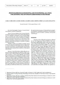
• the considered SBox set is activated by the same DPNs triggering the considered LR (DP N si =DP N sj ): SBi is added to Sj ; • the considered SBox set is activated by different DPN(s) with respect to all the considered LRs (!assignedSB = 1); a new set SN , composed of SBi , is added to M AP . Figure 1 offers an example of the resulting output of the proposed process. Four LRs are identified from the input dataflow specifications: LR1 contains all logic in common among the three networks and can be an always-on domain (i.e. it cannot be switched-off in any case since it belongs
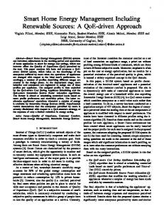
• PD4 contains only a SBox. Since SBoxes are simply combinatorial actors, PD4 needs only the Power Switch and the Isolation cells;
to all the input networks); LR4 is another shared region but it is in common between two out of the three networks; whereas, LR2 and LR3 at runtime will be activated only if the related network, α and β respectively, is activated.
Figure 1: Example of the developed LRs identification process.
3.2
• a Power Controller is required to properly generate the enable/restore signals for the PG cells. The MDC generated HDL is modified by adding an automatically generated Power Controller, which is mainly composed of a different finite state machine for each PD. This smart logic, once specified the input network to be executed, is in charge of properly generate the power management signals: a) the enable of the Power Switches and of the Isolation cells, b) the save of the State Retention cell (to store registers values before their shutting off), and c) the restore of the State Retention cells (to retrieve registers values once switched on). Depending on the adopted technology these signals may change in polarity and timing. For this reason, the user is required to specify a technology file, where all the above mentioned PG cells have to be specified and characterized. This information is also exploited during the CPF file generation. The CPF can be divided in two main parts: technology and power intent. Technology part sets the timing libraries (specified by the user) and individuates the lowpower cells (define_xxx cell commands) to be used within the technology specific physical libraries. The power intent part depends on the design and manages the PDs, PMs and the respective transitions. Here the power cells, specified on the technology part, are instantiated (create_xxx cells command) and associated to the design FUs (update_xxx cells command), accordingly with the PDs. All the logic belonging to the always-on domain is automatically associated to the default PD, which has no switching-off logic associated.
Power Gating Implementation
At the hardware level, we have exploited the LRs to implement power gating (PG). To this end, each LR will correspond to a different power domain (PD). At runtime, the PDs involving functional units (FUs) that are not involved in the current computation can be mutually switched off. A PD power-up (down) transition is executed in 4 clock cycles. Since all PDs are powered-up (down) at the same moment, transition time is independent from the number of PDs. For each input dataflow specification a different power mode (PM) (e.g. a fixed PDs setting) is created. Each PM represents a steady state of the design in which some PDs are active, while others are disabled, according to the LRs to be activated by the requested functionality. In addition to the design modification, a CPF file is also written in order to give to the synthesizer all the information needed to implement the PG. Starting from the same LRs identified in the example of Fig. 1, Fig. 2 shows the implementation of the PG in the resulting platform: • PD1, corresponding to the always-on logic, does not require any power management infrastructure; • PD2 and PD3 are power gated by means of three different types of cells, i.e. Power Switch, Isolation and State Retention cells;
Figure 2: Example of PG implementation on the generated hardware platform.
4.
ASSESSMENT
In this section we present the results obtained with the proposed methodology considering an image processing scenario (see Sec. 4.1). We are going to compare the results
achievable with the proposed automated power-gating (PG) methodology with the clock-gating (CG) one enabled within MDC (Sec. 4.2).
4.1
Application Scenario
As a proof of concept of the proposed power-aware design flow, we have adopted a use case involving an image zoom application. This latter scales an image by a given zooming factor interlacing pixels of the original image with other pixels coming from adaptive interpolations of the neighbouring ones. In this application seven computationally intensive code segments (computational kernels) have been identified and modelled as DPNs in terms of RVC-CAL dataflow specifications. Among them our methodology has identified 19 LRs and, in turn, 19 PDs have been defined in hardware. Table 1 summarizes the characteristics of the identified kernels with respect to the overall scenario (reported on the last row). Table 1: Zoom application: characteristics of the identified kernels. [# LR: LRs activated, # Actors: involved actors, # Sboxes: involved SBoxes, # :Occ occurrences of the kernel within the zoom application (data dependent, determined by the zoom factor, the size (128x128 pixels) and the characteristic of the input image)] Network # LRs # Sboxes # Actors # Occ. abs 7 51 1 3150 chgb 9 45 7 3072 cubic 6 21 10 1070 cubic conv 7 36 6 408 max min 7 51 1 1050 median 7 31 9 1069 sbwlabel 10 49 17 2722 multi-kernel 19 51 33 —
4.2
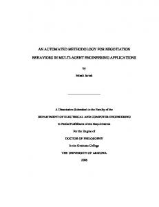
impact in the total power consumption (see last columns of Fig. 3 and Fig. 4). Adopting a smaller technology PG may lead to better results. Moreover, going through the results in terms of the single kernels consumption and splitting the two power contributions (static in Fig. 3 and dynamic in Fig. 4), as expected, PG is extremely beneficial in reducing the static dissipation. This is true both with respect to Zoom and Zoom cg and quite for all the kernels. Sbwlabel represents the only exception. As shown in Tab. 1, this kernel actives 10 upon 19 PDs and more than the half (17 upon 33) of the actors within the whole multi-kernel design. This means that the logic overhead introduced by PG during the execution of this specific kernel does not give any advantage, since most of the design is on. Note that (see Fig. 3), for this kernel, implementing power gating increments the static power consumption. Table 2: ASIC synthesis results (base = Zoom, pg = Zoom pg, cg = Zoom cg ) Design Area Power [µm2 ] % [µW ] %. Zoom 118271 — 5610 — Zoom cg 118695 +0.36 1557 -72.25 Zoom pg 224293 +89.9 2176 -61.21
Experimental Results
In this section we compare the proposed automatically generated PG design, Zoom pg, results with the MDC baseline one3 , Zoom, and the CG one, Zoom cg. The designs under test have been synthesized using Cadence SoC Encounter targeting a 90 nm CMOS technology. Table 2 shows area and power estimations of the three designs. Power results are calculated as the sum of single kernels contribution weighted for the number of their occurrences within the Zoom application. An invasive power saving technique, such as the PG, has a huge impact on the overall system area (+89.9%), while a non invasive one, such as the CG, has not a significant area increment (+0.36%). Then, it is possible to achieve real benefits from the former technique only if the adopted technology is small enough to make the area overhead negligible with respect to power saving. In our case, Zoom pg achieves more than the 60% of saving with respect to the baseline Zoom. However, Zoom cg allows better performance. This result is technology and application dependent. In fact, 90 nm technologies are far from the limit where the static power contribution exceeds the dynamic one. Therefore, leakage has no considerable 3 Design without any enabled power management methodology.
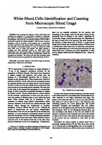
Figure 3: Static power results. Percentages defined respect to base Zoom Dynamic power consumption results are, again, kernel specific. Zoom pg in some cases (abs, min max and cubic conv ) leads to more than the 90% of saving, which is even better than Zoom cg. This is due to the fact that these are the smallest kernels. Therefore, when the smallest kernels are executed and the biggest are powered off, the overhead of the introduced power management logic is less than the benefits of having no switching activity in quite almost of the system. The same does not apply for the other kernels. The analysis of Fig. 3 and Fig. 4 leads to the conclusion that the decision of the power management strategy to be adopted in a certain context and the way it has to be implemented are highly application and technology dependent. The composition and occurrences of each kernel and, in turn, the composition and activation frequency of each PD, would highly affect the results. Numerical example in Tab. 3 shows as, with different occurrences of the kernels within the zoom application, PG can save more power than CG. Thus designers are required to carefully choose the strategy to implement, according to the overall scenario characteristics.
chitecture information we should deploy systems with adhoc region based power management.
Acknowledgment Prof. Luigi Raffo, Carlo Sau and Tiziana Fanni are grateful to Sardinia Regional Government for funding the RPCT Project (L.R. 7/2007, CRP-18324) that led to these results. Carlo Sau is also grateful to Sardinia Regional Government for supporting his PhD scholarship (P.O.R. F.S.E., European Social Fund 2007-2013 - Axis IV Human Resources).
6. Figure 4: Dynamic power results.Percentages defined respect to base Zoom
Table 3: New occurences ASIC synthesis result. [Percentages wrt to the baseline design without power-management]. Previous Zoom test Current Zoom test Network #Occ. #Occ. abs 3150 15142 chgb 3072 70045 cubic 1070 966 cubic conv 408 3072 max min 1050 341 median 1069 1253 sbw label 2722 1496 Tot.[µW ] %. Tot.[µW ] %. Zoom 5610 — 5544 — Zoom cg 1557 -72.25 581 -89.51 Zoom pg 2176 -61.21 400 -92.77
5.
CONCLUSIONS
In this paper we have proposed a fully automated power gating support for dataflow-based reconfigurable systems. Two are the main motivations of this work: 1) power reduction is of paramount importance in modern battery dependent designs and, with technology scaling, the available non invasive techniques are not sufficient; 2) systems heterogeneity and complexity are so challenging that manual strategies requires too much effort to be considered viable. To cope with these issues, in this paper we have demonstrated that, adopting a dataflow-based design flow, it is possible to exploit high-level information to partition the system architecture onto disjointed logic regions. These latter can then be orchestrated at the hardware level to implement invasive power saving strategies. The proposed methodology somehow extends the approach implemented within the Multi-Dataflow Composer tool for the automatic generation of a coarse-grained reconfigurable system. In this paper, we targeted power gating rather than clock gating. We have demonstrated the effectiveness of the proposed strategy in reducing the static power dissipation of a coarsegrained reconfigurable system for image processing applications. The comparison with a clock gated design highlighted some weakness of the proposed approach, but gave us precious hints to improve the overall strategy. With a smart combination of the two compared coarse-grained power saving strategies and exploiting high-level application and ar-
REFERENCES
[1] Open RVC-CAL compiler. http://orcc.sourceforge.net/, web. [2] E. Bezati, S. Casale-Brunet, M. Mattavelli, and J. W. Janneck. Coarse grain clock gating of streaming applications in programmable logic implementations. In Electronic System Level Synthesis Conf., 2014. [3] S. M. Carta, D. Pani, and L. Raffo. Reconfigurable coprocessor for multimedia application domain. Jrnl. VLSI Signal Proc. Syst., 44:135–152, 2006. [4] J. Eker and J.W. Janneck. Cal language report. Erl technical memorandum no. ucb/erl m03/48, University of California at Berkeley, 2003. [5] B. Jeff. Advances in big.little technology for power and energy savings. In ARM White Paper, 2012. [6] V. V. Kumar and J. Lach. Highly flexible multimode digital signal processing systems using adaptable components and controllers. EURASIP Jrnl. Appl. Signal Proc., 2006. [7] E. A. Lee and T. Parks. Dataflow Process Networks. In Proc. of the IEEE, pages 773–799, 1995. [8] H. J. M. Marek-Sadowska and S. R. Nassif. Benefits and costs of power-gating technique. In IEEE Int. Conf. on Computer Design, 2005. [9] J.-F. Nezan, N. Siret, M. Wipliez, F. Palumbo, and L. Raffo. Multi-purpose systems: A novel dataflow-based generation and mapping strategy. In Int. Symp. on Circuits and Systems, 2012. [10] F. Palumbo, N. Carta, D. Pani, P. Meloni, and L. Raffo. The multi-dataflow composer tool: generation of on-the-fly reconfigurable platforms. Jrnl. Real-Time Image Proc., 9(1):233–249, 2014. [11] F. Palumbo, N. Carta, and L. Raffo. The Multi-Dataflow Composer tool: A runtime reconfigurable HDL platform composer. In Conf. on Design and Arch. for Signal and Image Proc., 2011. [12] F. Palumbo, C. Sau, and L. Raffo. Coarse-grained reconfiguration: dataflow-based power management. In IET Computers & Digital Techniques, volume 9, pages 36–48, 2014. [13] Power Forward Initiative. A Practical Guide to Low Power Design, 2009. [14] A. Sathanur, A. Pullini, L. Benini, A. Macii, E. Macii, and M. Poncino. Timing-driven row-based power gating. In ACM/IEEE Int. Symp. on Low Power Electronics and Design, 2007. [15] Silicon Integration Initiative. Si2 Common Power Format SpecificationTM - Version 2.1, 2014. [16] D. Wingard. Noc power-management advantages. In Keynote Talks at IP-SoC Conf. and Exibition, 2013.