Automated Reverse Engineering of Hard-Coded GUI Layouts Christof Lutteroth Department of Computer Science The University of Auckland 38 Princes Street, Auckland 1020, New Zealand Email:
[email protected]
Abstract Most GUIs are specified in the form of source code, which hard-codes information relating to the layout of graphical controls. This representation is very lowlevel, and makes GUIs hard to maintain. We suggest a reverse engineering approach that is able to recover a higher-level layout representation of a hardcoded GUI using the Auckland Layout Model, which is based on the mathematical notion of linear programming. This approach allows developers to use existing code and existing tools, as well as specifications on a higher level of abstraction. We show how existing hard-coded GUIs can be extended to support dynamic layout adjustment with very little effort, and how GUIs can be beautified automatically during reverse engineering. Keywords: GUI layout, linear constraints, reverse engineering, beautification 1
Introduction
Most modern applications have graphical user interfaces (GUIs). It is an accepted fact that good GUIs are easier to use for casual users than textual command-line interfaces. However, development of GUIs can be much more difficult. First of all, a programmer has to choose a GUI toolkit, i.e. a library that implements the graphical controls of a GUI. Then, the programmer needs to access that toolkit using a supported programming language. The choice of a toolkit is influenced by many factors such as the operating system the application should run on, the graphical desktop environment that should be used, the preferred programming language, the popularity of and support for that toolkit, its cost, maintainability, flexibility and ease of use. As a result, there are many different GUI toolkits, accounted for by the different combinations of the aforementioned factors. Unfortunately, all these GUI toolkits have just as many differences as they have commonalities, and the differences are usually much subtler than the commonalities. Such differences include differences in the visual appearance of controls, differences in their behavior, and most of all, differences related to GUI layout. Modern GUI toolkits define components that support the arrangement of controls in a GUI, which are known as layout managers or layout engines. There is no accepted standard for layout managers, and the mechanisms and interfaces of different c Copyright 2008, Australian Computer Society, Inc. This paper appeared at the 9th Australasian User Interface Conference (AUIC2008), Wollongong, NSW, Australia, January 2008. Conferences in Research and Practice in Information Technology, Vol. 76. B. Plimmer, G. Weber, Eds. Reproduction for academic, not-for profit purposes permitted provided this text is included.
layout managers usually differ significantly enough to confuse and hamper developers. In (Lutteroth & Weber 2006) we have introduced a layout model that employs ordinal and linear constraints in order to specify a GUI layout. It has been developed further since to use the mathematical optimization technique of linear programming, and is now called the Auckland Layout Model (ALM). With linear programming as a formal basis, ALM allows GUI designers to specify GUIs in an exact, formal manner close to well-known mathematical concepts, so that specifications are also meaningful outside the context of a particular layout manager. Novel techniques such as ALM are interesting from an academic perspective, and would be useful from a practical perspective. But as a matter of fact, most developers do not use them. The majority of GUIs is hard-coded, i.e. defined on a very low level of abstraction through source code, and not specified using constraints or other abstract formalisms. Common development environments such as Visual Studio and Eclipse have visual GUI design tools, which allow developers to specify GUIs in a WYSIWIG fashion. The output of such tools is in most cases source code, mostly with no or very poor support for dynamic GUI layout, i.e. support for adjusting a GUI to a changing environment such as a new window size or screen resolution. The reverse engineering approach presented in this paper was developed with the intention to allow developers to enjoy the benefits of an expressive, constraint-based layout model such as ALM, without having to change the way they usually create their GUIs. That is, developers can use design tools that generate hard-coded GUIs, and still use ALM with only minimal modifications. The reverse engineering approach makes it possible to efficiently recover a higher-level specification from a hard-coded GUI, and immediately use that specification for dynamic layout. Section 2 describes the widely-used approach of hard-coding GUIs with a static layout, and points out its shortcomings. Section 3 outlines the main features of the ALM. Section 4 describes the reverse engineering algorithm that recovers an ALM specification from a hard-coded GUI, gives an example, and discusses some of its advantages. Section 5 describes how the reverse engineering algorithm can support beautification of GUIs. Section 6 discusses related work, and Sect. 7 concludes the paper. 2
Hard-Coded GUIs
Hard-coded GUIs are specified in the form of source code. The code creates controls, sets properties of each control such as location, size and visual appearance, and sets up the containment hierarchy. Developers either write the code by themselves, or more
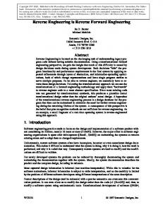
commonly, use GUI design tools. Such tools usually offer a graphical WYSIWIG interface with direct manipulation (Hutchins et al. 1985), which makes the specification of GUIs much more intuitive. However, their output consists usually of generated source code, so it is on the same low level as hand-coded GUIs. Figure 1 shows the GUI designer of the MS Visual Studio IDE, which is a typical example of GUI design tools. The panel in the middle contains a representation of the GUI that is edited. It shows the GUI just as it will look during runtime, with the difference that GUI controls can be selected, moved and resized by clicking and dragging them. In the left panel, a list of all available control types is shown, and dragging a control type entry into the GUI results in the creation of a new control. The right panel shows the properties of the control that is currently selected in the GUI, and allows developers to type in property values. While the GUI is modified, the IDE automatically generates corresponding source code. For example, the C# code that is generated for the button control currently selected in Fig. 1 includes the following lines, which set the control’s position, size and text label: 1 this.button2.Location = 2 new System.Drawing.Point(13, 52); 3 this.button2.Size = 4 new System.Drawing.Size(82, 36); 5 this.button2.Text = "button2"; This snippet of code expresses one of the biggest drawbacks of common hard-coded GUIs: the lack of dynamic layout. Positions and sizes of controls are hard-coded into the application, using pixels as a unit. However, the environments that most applications will be executed in during their life cycle differ: an application may be executed on an old PC with medium-resolution graphics, on a high-end workstation with a huge screen, or on a PDA with an extremely small display. Furthermore, the environment of a running application may change: users may want to change the amount of screen real-estate that is allocated to a GUI by changing the size of its window. Changes affecting the GUI may also happen within an application: for example, the content shown in a control may change so that its size needs to be adjusted. Such adjustments do usually not happen in a hard-coded GUI, or have to be implemented manually, which is cumbersome. Some GUI design tools allow a limited degree of automatic adjustment to window resizing, but support for this is rather crude and often requires additional work. Most GUI design tools provide some support for round-trip engineering, which means that the source code of the application can be changed while using the GUI design tool. This is usually realized with protected regions: the parts that are generated by the tool have to be shunned when editing the source code. Manual changes made in a protected region may interfere with the tool and either render the tool dysfunctional or get overwritten by the tool. As a result, it is not easy to mix generated and hand-written GUI code. For example, when using an algorithm to create and set up a GUI, it is effectively not possible anymore to use a GUI design tool. In general, on the level as shown in the source code snippet, GUI specifications are hard to maintain. The level of abstraction is low since the overall structure of the GUI is not specified explicitly, but emerges implicitly as the result of the static positions and sizes of the individual controls. Small changes in the GUI usually make many other changes necessary: for example, after changing the size of button2 in Fig. 1, we would most likely have to change the positions and sizes of all the other controls in order to
make the GUI look right. Other disadvantages of the representation of GUIs as source code are discussed in (Draheim et al. 2006). 3
The Auckland Layout Model (ALM)
The idea of the ALM is to provide abstractions for common GUI concepts to make the specification of adaptable GUIs easier. Instead of just capturing a single static configuration of controls, as is frequently done in hard-coded GUIs, the invariants of a GUI are specified. Using the apparatus of linear programming, those invariants can be used as constraints in an optimization process that results in the calculation of an adapted layout whenever circumstances change. The underlying mathematical notions make ALM specifications exact and give them meaning outside of the context of a particular GUI toolkit. ALM is not the first approach to employ linear programming for GUI layout, and many studies have shown that linear programming is a viable and suitable option for this domain, e.g. (Marriott & Chok 2002, Badros et al. 2001, Borning et al. 1997, Hosobe 2000, Bill et al. 1992). It has been shown that linear programming is expressive enough to model the constraints that are required for GUIs, and that is fast enough to be used for near real-time rendering. It has even been applied to more complex layout problems such as graph and tree layout. The problem with bare linear programming is the low level of abstraction of specifications, which makes is very cumbersome and error-prone to specify complex GUIs. Most of the aforementioned earlier approaches have dealt with GUI layout from a very formal, research-oriented perspective, often with a focus on the performance and capabilities of constraint solving, therefore bare linear programming was enough. ALM is different because its main focus is the usability from the perspective of the developer. In order to improve usability, ALM offers different layers of abstraction on top of bare linear programming that make it possible to specify the invariants of typical GUIs more conveniently. In the following, two of the main features of ALM are described: tabstops, areas and linear constraints. 3.1
Tabstops
The basic abstraction used in ALM is a tabstop. A tabstop represents a position in the coordinate system of a GUI. An x-tabstop represents a position on the x-axis and a y-tabstop a position on the y-axis. All positions and sizes in a layout are defined symbolically using tabstops as variables, and actual values are assigned to the tabstops during the layout process. In other words, the tabstops form a grid in which all the controls of a GUI are aligned. 3.2
Areas
The controls in a GUI are organized in rectangular areas, therefore ALM provides an abstraction that allows developers to specify such areas conveniently. An area a has the following form: a =def (x1 , y1 , x2 , y2 , content, sizemin, sizepref , sizemax) x1 , y1 , x2 , y2 are tabstops that delimit the area on its four sides. content holds the control that is shown in the area. sizemin , sizepref , sizemax are the minimum size, preferred size and maximum size of the area. Specifying a set of areas A implicitly defines a partial order on all x-tabstops and a partial order on
Figure 1: Editing GUIs in Visual Studio. all y-tabstops. The partial orders can be further extended with additional ordinal constraints. This information is used to define the overall tabular structure of a GUI. In (Lutteroth & Weber 2006) it was shown that partial orders have advantages over total orders, which are used by most approaches for tabular layout. Partial orders avoid over-specification and leave more flexibility to the layout manager, enabling layouts that adapt better to content size. The different size parameters allow developers to describe the invariants governing the dynamic resizing behavior of an area. sizemin and sizemax define the range of possible sizes; sizepref specifies a size that is regarded as optimal with regard to the control’s content and function. The layout manager tries to respect an area’s preferred size as much as possible, using the weighted cost minimization approach of linear programming in order to balance conflicting constraints. A constraint such as an area’s preferred size can be given priority over others by adjusting additional cost parameters. All size-related parameters are optional. 3.3
Linear Constraints
A layout with x-tabstops x0 , . . . , xm , m ∈ N, and ytabstops y0 , . . . , yn , n ∈ N can define a set C of linear constraints with: C ⊆ { a0 x0 + . . . + am xm + b0 y0 + . . . + bn yn ⊙ c | a0 , . . . , am , b0 , . . . , bn , c ∈ R ∧ ⊙ ∈ {≤, =, ≥}} It is possible to use different units for different constraints, e.g. hardware-dependent units such as pixels or absolute units such as cm. During the layout process, all values are transparently converted to pixels, using the properties of the active display. In the following we will examine different types of linear constraints, and describe how these can be useful for GUI layout. We will only consider equalities, but the concepts can be transferred to inequalities quite easily. Absolute constraints can be used to place tabstops at particular positions, or set the distance between tabstops to a fixed value. For example, if we want to set x-tabstop x3 at position 50, we would use a constraint x3 = 50. In order to set the width between
two tabstops x1 and x2 to 100, we would use a constraint x2 − x1 = 100. Such constraints are an easy way to specify the properties of a GUI that do not change dynamically. However, absolute constraints should be used with care because they may lead to over-constrained specifications that do not have a feasible solution. Relative constraints describe the position of tabstops, distances or proportion relative to others. This is useful in order to adapt the layout to changing circumstances, such as GUI display size or resolution changes. For example, one might want to position an x-tabstop x2 exactly between two other x-tabstops x1 and x3 . Let us assume that x1 ≤ x3 , then the constraint can be expressed as follows: x2 − x1 = x3 − x2 ⇔ −x1 + 2x2 − x3 = 0. Similarly, we can center an area that is delimited by x-tabstops x2 and x3 , x2 ≤ x3 , horizontally between two other x-tabstops x1 and x4 , x1 ≤ x4 : x2 − x1 = x4 − x3 ⇔ −x1 + x2 + x3 − x4 = 0. We only need to make sure that the area we want to center does not exceed the boundaries of x1 and x4 by specifying that x1 ≤ x2 or x3 ≤ x4 . If we want the width between x-tabstops x1 and x2 to be twice as much as the the width between x3 and x4 , we would use the following constraint: x2 − x1 = 2(x4 − x3 ) ⇔ −x1 + x2 + 2x3 − 2x4 = 0. Since a constraint can contain x-tabstops as well as ytabstops, it is also possible to specify the aspect ratio of an area. For example, we could specify an aspect ratio of 16:9 for an area (x1 , y1 , x2 , y2 , moviepanel) containing a control for displaying a video: x2 − x1 16 16 16 = ⇔ −x1 + x2 + y1 − y2 = 0. y2 − y1 9 9 9 When working with many hard constraints, i.e. constraints that have to be satisfied, it is easily possible to end up with a specification that contains conflicting constraints and is thus infeasible. Soft constraints make it possible to specify constraints that may not be satisfied fully if circumstances do not permit so. They are a common technique to deal with
over-constrained specifications (Meseguer et al. 2003, Hosobe & Matsuoka 2003), and have been used for GUI layout before (Badros et al. 2001). ALM allows developers to specify soft constraints with cost parameters that determine how easily a soft constraint gives way to other soft constraints. This can be used in order to define constraint hierarchies, i.e. soft constraints that are ranked according to their importance. 4
Reverse Engineering ALM Specifications
Algorithm 1 describes how a static, hard-coded GUI can be reverse engineered to an ALM layout specification. Function RecoverLayout is invoked after the GUI has been set up in an application and gets the parent control of the GUI as an argument. Its output is a layout specification (A, C) consisting of a set of areas A containing the child controls of parent and a set C of linear constraints. Since the the GUI is analyzed after it has been set up by the application, the approach will work even if a complex algorithm has been used to set it up. All it needs to do is read the actual positions and sizes of the controls in the GUI. Line 2 creates a new, empty layout specification. In lines 2 and 4 two important data structures are initialized, which are used to map positions in the GUI to tabstops in the layout specification. xtabs is a function that maps x coordinates to x-tabstops. Initially, it contains two elements that map the leftmost x-position to an x-tabstop xlef t , and the rightmost x-position to an x-tabstop xright . Analogously, function ytabs maps y coordinates onto y-tabstops. Both functions can be implemented efficiently using search trees. The for-loop starting at line 5 loops through all the controls in the GUI. For each control c, a new area anew that contains c is created and added to the layout specification. The following conditionals are used to find suitable tabstops for each of the sides of anew . In line 8 we test if the leftmost x-coordinate c.lef t of c is contained in the domain of xtabs, i.e. if this coordinate can be mapped to an existing xtabstop. If this is the case, that x-tabstop is used to specify the left boundary of anew . If no suitable existing x-tabstop is found, a new x-tabstop xnew is created and used to specify the left boundary of anew . Function xtabs is extended so that c.lef t maps to xnew . We proceed analogously to find tabstops for the three remaining sides of anew . Lines 32-37 indicate how heuristics can be used to choose size parameters for anew . In this illustration we use only a very simple heuristic: if the information content of control c is static, i.e. if it does not change, we assume that the developer already hardcoded a suitable size and keep the size constant by setting anew .sizemin = anew .sizemax = c.size. Whether the content of a control is static depends on its type: as a well-established convention, types such as buttons and labels are used to represent unchanging information to the user, whereas controls such as text boxes and list boxes often have a variable information content. For controls with potentially variable information content, we simply set anew ’s preferred size. More on this in Sect. 4.3. In lines 38 and 39 predicates are set on the tabstops that are used to specify anew ’s right and bottom bound: anew .right.lef tlink expresses that an order is imposed between anew .right and another x-tabstop to the left of it. The order is imposed by area anew , which implicitly contributes an ordinal constraint anew .lef t ≤ anew .right. Analogously, anew .bottom.toplink expresses that an order is im-
Algorithm 1 Reverse Engineering of a GUI. 1: function RecoverLayout(Control parent) 2: (A, C): Layout = (∅, ∅) 3: xtabs: (Z → XT abs) = {0 7→ xlef t , (parent.width − 1) 7→ xright } 4: ytabs: (Z → Y T abs) = {0 7→ ytop , (parent.height − 1) 7→ ybottom } 5: for all c: Control ∈ parent.children do 6: A ← A ∪ {anew } 7: anew .content ← c 8: if c.lef t ∈ dom(xtabs) then 9: anew .lef t ← xtabs(c.lef t) 10: else 11: anew .lef t ← xnew 12: xtabs ← xtabs ∪ {c.lef t 7→ xnew } 13: end if 14: if c.right ∈ dom(xtabs) then 15: anew .right ← xtabs(c.right) 16: else 17: anew .right ← x′new 18: xtabs ← xtabs ∪ {c.right 7→ x′new } 19: end if 20: if c.top ∈ dom(ytabs) then 21: anew .top ← ytabs(c.top) 22: else 23: anew .top ← ynew 24: ytabs ← ytabs ∪ {c.top 7→ ynew } 25: end if 26: if c.bottom ∈ dom(ytabs) then 27: anew .bottom ← ytabs(c.bottom) 28: else ′ 29: anew .bottom ← ynew ′ 30: ytabs ← ytabs ∪ {c.bottom 7→ ynew } 31: end if 32: 33: 34: 35: 36: 37: 38: 39: 40: 41: 42: 43: 44: 45: 46: 47: 48: 49: 50: 51: 52:
if c.type ∈ {Button, Label, . . .} then anew .sizemin ← c.size anew .sizemax ← c.size else anew .sizepref ← c.size end if anew .right.lef tlink ← true anew .bottom.toplink ← true end for for all (xposi , xi ): Z × XTab ∈ sort(xtabs − {0 7→ xlef t }) do if ¬xi .lef tlink then C ← C ∪{xi − xi−1 = xposi − xposi−1 } end if end for for all (yposi , yi ): Z × YTab ∈ sort(ytabs − {0 7→ ytop }) do if ¬yi .toplink then C ← C ∪ {yi − yi−1 = yposi − yposi−1 } end if end for return (A, C) end function
posed between anew .bottom and another y-tabstop above of it. Both predicates are used in the last part of the algorithm, which inserts constraints for the margins between the controls. After the first loop, in lines 41-45, we iterate through all the elements of function xtabs, excluding the element for the leftmost x-tab. The elements are iterated through in ascending numerical order of x-coordinates. If xtabs was implemented as a search tree, then the elements are already represented in the right order so that no additional effort is necessary. For each element (xposi , xi ), we test if the tabstop xi has been connected to a previous tabstop by a constraint, which is expressed by xi .lef tlink. If this is the case, it means that xi serves as the right boundary of an area in A. If it is not the case, it means that to the left of xi there is a margin separating areas, and we add a constraint to C that makes this margin part of the specification. The constraint sets the distance between xi and its predecessor to the distance as it is set in the hard-coded GUI. In lines 46-50, we proceed analogously for the elements in ytabs. The algorithm is very fast in practice and can be invoked whenever GUI has been changed by the application. This makes it possible to reverse engineer a new layout specification if, for example, the application has added new controls to the GUI or changed existing ones. As we will see in the following section, after reverse engineering the ALM layout manager enables the GUI to adapt its layout dynamically to changes such as a different window size. 4.1
Example
In this section we want to demonstrate how easy this reverse engineering technique makes it to use ALM with an existing hard-coded layout. Let us consider the example GUI in Fig. 1. In order to use ALM, only a few lines of source code have to be added to the definition of the parent control of the GUI. In our example, the parent control is defined by a class Form1, which represents the application window: 1 2 3 4 5 6 7 8 9 10 11 12 13 14 15 16
public partial class Form1 : Form { ALM.ALMEngine le = new ALM.ALMEngine(); public override LayoutEngine LayoutEngine { get { return le; } } public Form1() { InitializeComponent(); } }
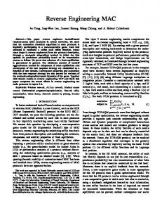
Lines 3-10 were added to the existing code. No existing line had to be modified. Lines 3 and 4 add a member variable le to the class that contains an ALM layout manager object. Lines 6-10 overwrite the getter function for property LayoutEngine, which contains the layout manager used for a control. Instead of returning the default layout engine that does not perform any layout at all, the ALM layout manager object is returned. Whenever layout parameters such as window size change, the layout manager is invoked and can adapt the GUI. Figure 2 illustrates how the GUI is adapted for different window sizes. As specified in Algorithm 1, the controls with constant visual information content, i.e. the two buttons, keep their initial dimen-
sions. The controls with inherently variable information content, i.e. the text box and the list box, adjust their sizes to the available space. When shown initially, the layout of the GUI looks exactly as that of the hard-coded GUI. 4.2
Elimination of Redundancy
The recovered ALM specification is more abstract than the hard-coded specification not only because of the differences in representation or the information that is gained through the use of heuristics. In addition, the reverse engineering process eliminates redundancy in the layout specification: instead of specifying all locations and sizes of controls separately, information about their alignment is recovered and expressed in a non-redundant form: • If several controls share a boundary, instead of repeating the numerical coordinate in every control, it is expressed once as a tabstop and all corresponding areas are just referring to that tabstop. • If several controls are separated on one side from other controls by the same margin, instead of expressing that margin as a difference in the position of every control, it is represented once as a linear constraint that specifies a distance between two tabstops. The higher level of abstraction has clear benefits. The amount of data is reduced in favor of a representation that captures the relations present in the layout. This makes layout specifications much easier to read and understand. Furthermore, if information that is shared by several entities is specified once at a single place, it is much easier to maintain. For example, global margins can be changed by modifying small number of linear constraints instead of a large number of control positions. 4.3
Heuristics for Resizing Behavior
In Algorithm 1 we have used a simple heuristic for choosing appropriate size parameters for areas. If a control type is used to represent a static information content, then the size of a respective control is kept static as well. For example, buttons contain usually only a simple textual label or sometimes an image. Neither the label nor an image change during runtime because this would confuse users: the relation between the label or image, the location and the function of a button is kept unchanged to help users invoke program functions more easily. The size of a button also depends on usability considerations such as Fitts’ law (MacKenzie 1992), which predicts that the speed a control can be accessed with increases with its size. This means that controls cannot be arbitrarily small, and that more important controls are usually assigned a larger size. However, from a certain size onwards a control is conveniently accessible, and enlarging it may not be very useful anymore. The heuristics of keeping the size of static controls constant makes the reasonable assumption that an adequate size was assigned to each static control in the hard-coded GUI. It is not possible to validate this assumption automatically because of the semantic nature of factors such as importance of a control, but usually this unnecessary. As we will see later on, it is still possible to change ALM’s parameters manually for a reverse engineered layout. Other types of controls that can be considered static are groups of check boxes, radio buttons, drop-down boxes and passive controls such as images or textual labels.
Figure 2: Resizing a GUI after reverse engineering. Examples for control types with varying information content are list boxes, text boxes, drawing panels – all controls that an application or a user can potentially add new data to. In order to accommodate for this variation of size, and to use additional free space for user input, which has to be considered as valuable, the size of such controls is held flexible. The layout manager adjusts those components taking into account their preferred size. Some GUI toolkits provide functions that calculate a preferred size based on the content of a control. If such functionality is available, it can be used to set the sizepref parameter of an area. If such information is not given by a toolkit, we can implement such functions by ourselves. Algorithm 1 uses a very simple approach that sets sizepref to the size hard-coded into the GUI. If the hard-coded GUI chooses the size of a control appropriately, which is a reasonable assumption, then the value of sizepref will be suitable as well. Simplistic heuristics such as the ones used in Algorithm 1 are good for illustration purposes, but need to be refined. For example, if the list box in the bottom-left corner of our example was replaced by a static control, say a button, then the height of the GUI would remain constant as the height of all the buttons and their vertical margins. In order to prevent such a situation, soft constraints have to be used. The basic idea is that hardly any hard constraints are used at all, but instead the invariants of areas and margins are expressed with soft constraints that can be violated with differing degrees of ease. As mentioned in Sect. 3.3, soft constraints have cost parameters that determine how easily they can be violated. A good heuristics for resizing behavior has to choose such cost parameters for all size constraints. A simple choice for cost parameters are penalty coefficients that determine how strongly a violation adds to the value of the linear programming objective function. It is possible to set different penalty coefficients for positive and negative constraint violation, as described in (Badros et al. 2001). Penalty coefficients make heuristics possible that set how easily an area or a margin can be expanded, and how easily it can be compressed. Important controls can be made hard to compress, but easy to expand. Unimportant controls and margins can be made to give way very easily. Constraints that set a healthy minimum or maximum size for an area can be configured so that they are only violated in extraordinary circumstances. In order to choose adequate heuristics, user interface models such as (Parush et al. 1998) can be applied. This makes it possible to determine certain layout parameters automatically on the basis of model predictions. Good models are ones that were validated empirically, i.e. it was tested whether the model is able to make good predictions with a certain confidence. Some models such as the metric for layout appropriateness presented in (Sears 1993) require
additional information about the tasks that are supported by a user interface. Such information could be provided manually, or could be reverse engineered as well to a certain degree. 4.4
Refinement of Recovered Layouts
ALM specifications can be further refined, i.e. extended and/or changed after reverse engineering. This can either happen by refining a recovered ALM specification offline and using it to define the layout of a GUI statically, or by refining the recovered layout of a GUI dynamically. In the case of static refinement, developers would reverse engineer a specification, edit it possibly with tool support, and then use it as explicit input for a layout manager. In the case of dynamic refinement, reverse engineering of a hardcoded GUI and refinement would both take place during runtime. Static refinement is more thorough and a more structured approach when dealing with large refinements, whereas dynamic refinement can be more time efficient for smaller changes. In the following, we want to briefly consider dynamic refinement, which is more challenging. In order to make dynamic refinement possible, the ALM specification recovered from a hard-coded GUI is accessible in a structured manner during runtime. Not only can it be introspected, but also changed and extended. For example, the following changes to the constructor of Form1 modifies the recovered layout so that the margin between the two buttons is omitted: 1 2 3 4 5 6 7 8
public Form1() { InitializeComponent(); le.RecoverLayout(this); ALM.LayoutSpec l = le.LayoutSpec; l.AreaOf(button1).Bottom = l.AreaOf(button2).Top; }
Line 4 explicitly invokes the reverse engineering process, so that the recovered ALM specification can be accessed in line 5. Line 6 and 7 use a method AreaOf to get the areas corresponding to particular controls in the GUI, and access their tabstops accordingly. 5
Beautification
It is possible to extend the reverse engineering algorithm so that the recovered layout is beautified according to some criteria. In the following several extensions for beautification are discussed. 5.1
Fuzzy Alignment
When designing a GUI with a WYSIWIG tool, it is very common that controls are only imperfectly aligned to each other due to imprecisions of human
psychomotility. A control might just be misplaced by a single pixel, and the deviation might only be visible under closer observation. Small misplacements can easily be corrected by modifying Algorithm 1 slightly. Only the conditions of the if-statements in lines 8-31 have to be changed: instead of testing if an exact coordinate is already mapped to a tabstop, we test if the coordinate is close to a coordinate that is already mapped. In line 8, for example, we would test if xpos − ǫ ≤ c.lef t ≤ xpos + ǫ with xpos ∈ dom(xtabs). That is, we allow for a degree of fuzziness ǫ that determines how far a control can be misplaced and still be aligned to the closest mapped coordinate. This can be done very efficiently if we implemented, as suggested, the function xtabs and ytabs with search trees. One can determine which coordinate in the tree comes closest to a given search key by descending from the root to the level of the leaves and comparing adjacent leaf nodes. A similar approach can be taken to align controls to a given artificial grid. 5.2
Standardized Margins
Similarly to the alignment of controls, standardized sizes of margins are considered as aesthetically pleasing. For example, if the left margin between the border of a window and its controls has a different size than the right margin, the GUI would have an unbalanced look. Similar effects are caused by differing margins between controls. Algorithm 1 can be adjusted to automatically set the widths and heights of margins to standard values. Margins are added to a specification in lines 43 and 48 in the form of absolute linear constraints. In the original version, the distance between the tabstops delimiting the margin is set to the distance in the hard-coded GUI. This can be easily replaced by a standard value dmargin so that the constraint in line 43, for example, would simply look like this: xi − xi−1 = dmargin Furthermore, we can differentiate the margins between the window boundaries and controls from the margins between controls. For example, a GUI designer might want to eliminate all margins between window boundaries and controls to save valuable screen space. This can be achieved by treating the first and the last elements of the lists that are used in the loops in lines 41 and 46 different from the other elements. 5.3
Standardized Sizes
A GUI designer might want to give similar controls the same size. Same heights within a row of controls and same widths within a column of controls is already enforced through alignment, but a GUI may look more appealing if, for example, the controls in the same column have also the same heights. This can be achieved by modifying lines 32-37 so that the size properties of areas with similar controls are set accordingly. The set A of all recovered area specifications can be accessed to find an area that matches the area anew currently being processed, and use its size parameters for anew . Similarity of areas can be determined, for example, by looking at the type of the contained control, its content and proximity. When dealing with a large number of controls, the matching of areas can be sped up by using appropriate index data structures such as search trees.
5.4
Inference of Linear Constraints
Frequently, GUIs contain rows or columns of similar controls. If this is the case, it may be appropriate to define relative linear constraints so that the heights or widths of the matching rows or columns are kept in a certain proportion to each other. For example, two adjacent columns of similar controls may look nicer if the proportion of their widths stays the same, no matter how their window is resized. Columns and rows with similar controls can be found by keeping appropriate data structures that provide efficient associative access to characteristics such as control type and size for each consistent row and column. For two similar columns delimited by x1 , x2 and x3 , x4 , for example, we can insert a constraint x2 − x1 = c(x4 − x3 ) with c being the proportion of their preferred widths. 5.5
Adjustment of Units
GUIs can be rendered consistently on different screen resolutions if their sizes are specified in real-world physical units such as cm. However, hard-coded GUIs usually use pixels as unit, which means that GUIs appear smaller on screens with higher resolution. The configuration of area sizes in lines 32-37 of Algorithm 1 can be extended to convert the hard-coded pixel sizes into physical units, by using an appropriate scaling. The right scaling can be found by comparing the size of the text in the hard-coded GUI with the preferred text size, which is a common user-defined parameter of modern graphical desktop environments and a good indicator for the visual psychomotor accuracy of the user. Like this, the preferred sizes of controls in a GUI can be chosen so that the user can interact with them conveniently. The layout manager may still have to violate such preferred values in case of screen space scarcity, but it will try to balance all requirements adequately through cost minimization. 6
Related Work
Merlo et al. (1995) discuss a reverse engineering technique for user interfaces that employs a AUIDL, which is a user interface description language. With AUIDL, it is possible to describe structural and behavioral aspects of GUIs. Presentational characteristics can be specified with containment and importation, i.e. by giving a containment hierarchy of GUI controls and by allowing controls to import property values from other controls. Importation can be used to specify alignment of controls to common positions or same-size constraints, but is by far not as powerful as linear constraints. Reverse engineering is performed from a very specific and limited kind of character-based user interfaces. The focus is mostly on the behavioral aspects of the user interface. Other approaches for reverse engineering of character-based user interfaces such as (Stroulia et al. 2003) recover user interface layout by analyzing projection profiles. Occurrences of certain characters are counted for each line and each column in order to find boundaries between the elements in the user interface, and thus infer alignment properties. While such techniques are effective for character-based user interfaces, they cannot be used for GUIs. Vaquista (Vanderdonckt et al. 2001) is a reverse engineering approach for web pages with the goal to generate equivalent GUIs for other platforms. It uses the containment hierarchy as the main specification for layout, e.g. a table layout can be analyzed recursively to produce a hierarchy of rows or columns with
other controls in them. The layout of HTML forms is captured using simple layout relations such as alignment, justification and distribution. This approach is limited to web pages, and its focus is on reverse engineering of a user interface as a means of interaction, in contrast to exact user interface layout. USIXML (Limbourg et al. 2004) is a user interface description language that can be used to specify user interfaces on different levels of abstraction. For concrete user interfaces, it supports layout specification with a containment hierarchy and an alignment relation. ReversiXML (Bouillon et al. 2005) is a language for the description of user interface reverse engineering rules that generate an USIXML specification. It can be used to match patterns in specification languages such as HTML, e.g. to recover layout attributes and set according attributes on USIXML interaction objects. However, it does not operate on a level that enables inference of geometric relations with metric information. Tools for user interface design by demonstration (Myers 1988) recover a GUI specification from example data given by the user. Their main idea is that of programming-by-example: users can design a GUI by drawing a prototypical screenshot, which is automatically or semi-automatically generalized and transformed into a real GUI. Most tools use rules in order to choose and configure controls appropriately, and perform some beautification tasks such as inference of alignment constraints. Some tools only offer more abstract drawing operations such as predefined shapes and focus more on the behavioral aspects of GUIs, e.g. (Myers et al. 1993). Other tools focus on the recognition of controls and allow users to interact more directly. For example, JavaSketchIt (Caetano et al. 2002) is capable of sketch-based user interface recognition, using visual grammars. In contrast to the approach presented here, such tools do not support reverse engineering of hard-coded GUIs but start on a lower level of abstraction, usually that of geometric shapes. Their layout models are less expressive than ALM, and can sometimes only handle static layout. It would be interesting to combine ALM with approaches for user interface design by demonstration. Algorithms such as Turbo Recognition (Tokuyasu & Chou 2001) use statistical analysis to recover rectangular layout specifications from raw images. The main challenge of such algorithms is the recognition of horizontal and vertical borders of homogeneous areas blurred by noise. Consequently, they operate on a much lower level than the approach presented here. However, once rectangular areas are recognized, models such as ALM can be used for layout representation. That is, the approaches for further abstraction and beautification presented in this paper can be applied to get a higher benefit from the data recovered by low-level recognition. 7
Conclusion
Our work leads us to the conclusion that reverse engineering of hard-coded GUIs into higher-level specifications is desirable, and that it can be performed successfully using the Auckland Layout Model. The presented algorithm can be used to achieve the following goals: • Fast, dynamic recovery of an ALM specification for adding resizing capabilities to hard-coded GUIs with very little effort. • Elimination of redundant specifications for the improved maintenance of GUIs.
• Static and dynamic refinement of GUI specifications. • Beautification of GUIs for improving aesthetics and usability. The reverse engineering algorithm makes it possible to use existing tools for GUI development while using specifications that are situated on a higher level of abstraction. In the future, we want to develop tool support specifically for ALM. This would allow developers to create GUIs using ALM’s linear constraints and higher-level constructs directly, while enjoying the benefits of a visual design environment. References Badros, G. J., Borning, A. & Stuckey, P. J. (2001), ‘The cassowary linear arithmetic constraint solving algorithm’, ACM Trans. Comput.-Hum. Interact. 8(4), 267–306. Bill, T., Lundell, B., McDonald, J. & Sannella, M. (1992), Bricklayer: window layout using linear programming, Technical report, University of Washington. Borning, A., Marriott, K., Stuckey, P. & Xiao, Y. (1997), Solving linear arithmetic constraints for user interface applications, in ‘UIST ’97: Proceedings of the 10th Annual ACM Symposium on User Interface Software and Technology’, ACM Press, pp. 87–96. Bouillon, L., Limbourg, Q., Vanderdonckt, J. & Michotte, B. (2005), Reverse engineering of web pages based on derivations and transformations, in ‘LA-WEB ’05: Proceedings of the Third Latin American Web Congress’, IEEE Computer Society, Washington, DC, USA, p. 3. Caetano, A., Goulart, N., Fonseca, M. & Jorge, J. (2002), Javasketchit: Issues in sketching the look of user interfaces, in ‘Proceedings of the AAAI Spring Symposium on Sketch Understanding’, pp. 9–14. Draheim, D., Lutteroth, C. & Weber, G. (2006), Graphical user interfaces as documents, in ‘Proceedings of CHINZ 2006 – 7th International Conference of the ACM’s Special Interest Group on Computer-Human Interaction’, ACM Press. Hosobe, H. (2000), A scalable linear constraint solver for user interface construction, in ‘CP 2000: Proceedings of the 6th International Conference on Principles and Practice of Constraint Programming’, Springer, pp. 218–232. Hosobe, H. & Matsuoka, S. (2003), ‘A Foundation of Solution Methods for Constraint Hierarchies’, Constraints 8(1), 41–59. Hutchins, E., Hollan, J. & Norman, D. (1985), ‘Direct Manipulation Interfaces’, Human-Computer Interaction 1(4), 311–338. Limbourg, Q., Vanderdonckt, J., Michotte, B., Bouillon, L., Florins, M. & Trevisan, D. (2004), USIXML: A User Interface Description Language for Context-Sensitive User Interfaces, in ‘AVI’04: Proceedings of the ACM Workshop on Developing User Interfaces with XML’, ACM Press, pp. 55–62. Lutteroth, C. & Weber, G. (2006), User interface layout with ordinal and linear constraints, in ‘AUIC ’06: Proceedings of the 7th Australasian User Interface Conference’, Australian Computer Society, Darlinghurst, Australia, Australia, pp. 53–60.
MacKenzie, I. (1992), ‘Fitts’ law as a research and design tool in human-computer interaction’, HumanComputer Interaction 7(1), 91–139. Marriott, K. & Chok, S. S. (2002), ‘Qoca: A constraint solving toolkit for interactive graphical applications’, Constraints 7(3-4), 229–254. Merlo, E., Gagne, P., Girard, J., Kontogiannis, K., Hendren, L., Panangaden, P. & De Mori, R. (1995), ‘Reengineering user interfaces’, Software, IEEE 12(1), 64–73. Meseguer, P., Bouhmala, N., Bouzoubaa, T., Irgens, M. & S´anchez, M. (2003), ‘Current Approaches for Solving Over-Constrained Problems’, Constraints 8(1), 9–39. Myers, B. (1988), Creating user interfaces by demonstration, Academic Press Professional. Myers, B. A., McDaniel, R. G. & Kosbie, D. S. (1993), Marquise: creating complete user interfaces by demonstration, in ‘CHI ’93: Proceedings of the INTERACT ’93 and CHI ’93 conference on Human factors in computing systems’, ACM Press, pp. 293–300. Parush, A., Nadir, R. & Shtub, A. (1998), ‘Evaluating the layout of graphical user interface screens: Validation of a numerical computerized model’, International Journal of Human-Computer Interaction 10(4), 343–360. Sears, A. (1993), ‘Layout appropriateness: a metric for evaluating user interface widget layout’, IEEE Transactions on Software Engineering 19(7), 707– 719. Stroulia, E., El-Ramly, M., Iglinski, P. & Sorenson, P. (2003), ‘User Interface Reverse Engineering in Support of Interface Migration to the Web’, Automated Software Engineering 10(3), 271–301. Tokuyasu, T. & Chou, P. (2001), Turbo recognition: a statistical approach to layout analysis, in ‘Proceedings of the SPIE Conference on Document Recognition and Retrieval’, International Society for Optical Engineering. Vanderdonckt, J., Bouillon, L. & Souchon, N. (2001), Flexible reverse engineering of web pages with vaquista, in ‘WCRE ’01: Proceedings of the Eighth Working Conference on Reverse Engineering (WCRE’01)’, IEEE Computer Society, Washington, DC, USA, p. 241.