Automated Transmitter Beam Size and Divergence Control in the SLR2000 System J. Degnan, G. Jodor, and H. Bourges 1.
Sigma Space Corporation, 4801 Forbes Blvd., Lanham, MD 20706 USA.
Contact:
[email protected] /Fax: +01-301-577-9466
Abstract Signal count rates and orbital time bias estimates vary widely over the range of satellite altitudes. In order to obtain an acceptable photon count rate for the higher satellites (e.g. LAGEOS, ETALON, GPS) while still meeting eye safety requirements at the telescope exit aperture, we must tightly control both the SLR2000 transmit beam diameter at the exit aperture and the final beam divergence half angle. For lower satellites, the uncertainty in the satellite angular position and the signal count rates are both relatively high. Thus, the SLR2000 design targets a nominal range of beam divergence half angles between 4 arcsec (larger than the combined effects of mount pointing jitter and atmospherically induced spreading and beam wander) for high satellites and 13 arcsec (adequate to accommodate time bias uncertainties) for LEO satellites. A modified commercial beam expander in the transmitter is used to maintain a constant transmitter beam size at the telescope exit aperture for eye safety while simultaneously varying the beam divergence to accommodate the various satellite altitudes and angular uncertainties. Introduction SLR2000 adjusts transmitter beam divergence based on satellite altitude and orbital knowledge, i.e. narrower for high satellites (+ 4 arcsec min) and wider for low satellites (+ 13 arcsec max). For eye safety reasons, the divergence must be adjusted while keeping the beam diameter at the telescope exit aperture fixed. It has been shown [Klein and Degnan, 1972] that a ratio of telescope diameter to Gaussian beam diameter (between 1/e2 intensity points) equal to 1.12 maximizes the amount of energy on the satellite. Thus, for the 40 cm SLR2000 telescope, the optimum beam diameter is 35.7 cm, and final divergence is set by adjusting the phase front curvature of the transmit beam at the telescope exit window. The Special Optics Beam Expander (SOBE) for controlling spot size and divergence is located on the transceiver bench in the transmitter path. This paper outlines our technical approach and additional details can be found elsewhere [Degnan, 2005]. Paraxial ray matrix theory can be applied to Gaussian laser beams if the beam is represented by the complex parameter
λ 1 1 = −j q( z ) R( z ) πω 2 (z )
(1)
where λ = 532 nm is the laser wavelength in the propagation medium and R(z) and ω(z) are respectively the wavefront curvature and spot radius (measured from the beam center to the 1/e2 intensity point) of the Gaussian beam at the location z along the propagation axis. If q(z0) is the Gaussian beam parameter at the output of the SOBE, then the Gaussian beam parameter at the exit window of the telescope is given by the ABCD Law [Verdeyen, 1989]
⎛ 1 ⎞ ⎟ C + D⎜⎜ q( z 0 ) ⎟⎠ 1 ⎝ = (2) q(z ) ⎛ 1 ⎞ ⎟⎟ A + B⎜⎜ ⎝ q(z 0 ) ⎠ In (2), A, B, C, and D are the ray matrix coefficients which propagate the rays from the SOBE to the telescope exit aperture. Separating (2) into its real and imaginary parts yields the following expressions for the wavefront curvature and beam spot size at the telescope exit aperture, i.e. 2
R( z ) =
⎛ B ⎞ ⎛ Bλ ⎞ ⎟ ⎜⎜ A + ⎟ +⎜ R( z 0 ) ⎟⎠ ⎜⎝ πω 2 ( z 0 ) ⎟⎠ ⎝
2
⎛ ⎛ λ ⎞ B ⎞ D ⎞⎛ ⎟ ⎟⎟ + BD⎜⎜ ⎜⎜ C + ⎟⎟⎜⎜ A + 2 ⎟ R( z 0 ) ⎠ R( z 0 ) ⎠⎝ ⎝ ⎝ πω ( z 0 ) ⎠
(3a)
2
and 2
2
⎛ B ⎞ ⎛ Bλ ⎞ ⎟ ⎟ +⎜ ω (z ) = ω (z 0 ) ⎜⎜ A + (3b) R( z 0 ) ⎟⎠ ⎜⎝ πω 2 ( z 0 ) ⎟⎠ ⎝ We can now compute the ABCD matrix for the transmitter at the satellite target by multiplying the system matrix by the propagation matrix and letting the target range, r, approach infinity, i.e.
( A + rC )Γ' I rI AΓ' BΓ' = lim r →∞ 0 I CΓ' DΓ' r →∞ CΓ'
FF = lim
(B + rD )Γ' DΓ'
≅
rCΓ' rDΓ' CΓ' DΓ'
(4)
Substituting A = rC and B = rD into (3) yields the following expressions for the phase front curvature and spot size at the satellite R(r ) = r
(5a)
and
ω (r ) = rω (z 0 )
⎛ ⎛ ω (z 0 ) D ⎞ ⎛ Dλ ⎞ λ ⎞ 1 ⎟ =r ⎟ ⎜⎜ C + ⎟⎟ + ⎜⎜ + ⎜⎜ 2 2 2 ⎟ R( z 0 ) ⎠ ⎝ πω (z 0 ) ⎠ mt R ( z 0 ) ⎝ πω ( z 0 ) ⎟⎠ ⎝ 2
2
2
(5b)
where, for SLR2000, C = 0 and D = 1/mt = 0 where mt = 30.48 is the total magnification in the transmit path [Degnan, 2005]. As expected, the wavefront curvature in the far field equals the distance from the telescope aperture and the spot size grows linearly with that distance. Equation (5b) can therefore be used to compute the beam divergence half angle (center to 1/e2 intensity point) of the transmitter in the far field, i. e.
θt ≡
ω (r ) r
=
ω (z 0 ) mt
⎛ ⎛ πω 2 ( z 0 ) ⎞ 1 λ ⎞ λ ⎜ ⎟ ⎟ + = 1 + ⎜⎜ ⎟ ( ) R z πmt ω ( z 0 ) λ R 2 ( z 0 ) ⎜⎝ πω 2 ( z 0 ) ⎟⎠ 0 ⎠ ⎝ 2
2
(6)
Note that the far field divergence depends on both the spot size, ω(z0), and the phase front curvature, R(z0), at the output of the SOBE.
Technical Approach
The approach we followed for controlling SLR2000 beam size and divergence was as follows: 1. Measure transmitter gaussian beam radius (.969 mm) at entrance plane to beam expander, raw beam half divergence, and compute gaussian complex q-parameter for the input beam 2. Choose a COTS beam expander with an adequate exit aperture (>40cm/30.48 = 13.1 mm) and magnification range (~13.1 mm/ 2mm = 6.5) and at least two control elements for independently adjusting beam size and phasefront curvature at the output. 3. Develop dynamic ray model for unit including variable lens spacings. 4. Test dynamic ray model against sophisticated ray tracing program such as ZEMAX. 5. Calibrate beam expander servo controllers at various magnifications. 6. For each divergence value, use the gaussian beam propagation law to compute the complex q-parameter of the expander output beam and the lens spacings which produce that parameter. 7. Compute lookup table specific to laser transmitter
ω in
a. Spot Size Measurement Exit
Beam Profiler
Beam Expander
Input beam radius (to 1/e2 intensity point) Transmitter Beam
f
b. Divergence measurement
Transmitter Beam
Beam Profiler
θ in =
ωf f
Divergence half-angle
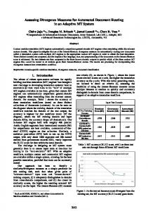
Figure 1: Measuring the Gaussian parameters of the raw transmit beam: (a) input radius; and (b) far field beam divergence.
The beam radius and divergence of the transmitter beam at the input to the SOBE were measured using a standard beam profiler as in Figure 1. The complex Gaussian beam parameter was then computed from the formula 2 ⎞ λ λ ⎛⎜ ⎛ πωinω f ⎞ 1 1 ⎟ ⎜ ⎟ 1 ≡ −j = − − j (7) 2 2 ⎜ ⎜ ⎟ ⎟⎟ πωin πωin ⎜ ⎝ λf ⎠ qin Rin ⎝ ⎠ The commercial version of the Special Optics Beam Expander Model 56C-30-2-8X is normally operated under a Labview environment and is designed to provide a wide range of beam magnifications (2X to 8X) at the desired wavelength. Sigma has reconfigured the unit to operate with two National Aperture Motor Controllers under a more flexible software control. The optical unit consists of five lenses: a moving singlet at the input end, a moving doublet in the middle, and a larger aperture stationary doublet at the output end as in Figure 2. The moving singlet and doublet are
driven by two independent stepper motors. Their positions are determined by counting the number of steps from a home position as defined by two limit switches.
Positive Limit Switch Motor 2 and Negative Limit Switch Motor 1
Negative Limit Switch Motor 2
Home position Motor 1 (Zero)
-M1
Home Switch Motor 1 Moving Singlet Lens Group #2 Motor 2
Positive Limit Switch Motor 1
Moving Doublet Lens Group #1 Motor 1
Home Switch Motor 2
Home position Motor 2 (Zero)
-M2
Large Stationary Doublet Lens
Figure 2: Optomechanical configuration of Special Optics Beam Expander Model 56C-30-2-8X. The expander has entrance and exit apertures of 10 mm and 30 mm respectively.
d1
Stationary Doublet
d2
Moving Moving Doublet Singlet
Figure 3: Optical layout of Special Optics Model 56C-30-2-8X Beam Expander.
Using an optical prescription provided by Special Optics, we computed a “dynamic ray matrix” for the SOBE depending on the variables d1 and d2 defined in Figure 3. The result was A (d , d ) BSO (d1 , d 2 ) M SO (d1 , d 2 ) = SO 1 2 (8) CSO (d1 , d 2 ) DSO (d1 , d 2 )
where ASO (d1 , d 2 ) = A0 + A1 d1 + A2 d 2 + A12 d1 d 2
(9a)
BSO (d1 , d 2 ) = B0 + B1 d1 + B2 d 2 + B12 d1 d 2
(9b)
C SO (d1 , d 2 ) = C 0 + C1 d1 + C 2 d 2 + C12 d1 d 2
(9c)
DSO (d1 , d 2 ) = D0 + D1 d1 + D2 d 2 + D12 d1 d 2
(9d)
and the computed coefficients appearing in (9) are summarized in Table 1. Table 1: Summary of coefficients appearing in the SOBE ray matrix
A B C D Suffix 1.995665379968 0.028752151456 46.402866180544 1.170293617808 0 63.683551232 1.442710470656 -460.710690944 -10.437108561152 1 -45.765735168 2.505955512 -1230.503704704 67.377646836 2 -1634.569158656 89.502715904 11825.086257152 -647.496210368 12
Setting CSO =0 and ASO equal to integer magnifications between 2 and 8, the ray matrix predictions of the interlens spacings, d1 and d2, computed from (9a) and (9c) were then compared to those of a popular ray tracing program, ZEMAX, and the predictions were found to agree within a few tens of microns for all magnifications. The two motor positions, relative to their respective home limit switches, are related to the interlens spacings via the equations
M 1 = a − d1
and
M 2 = b − d1 − d 2
(10)
Following our inhouse calibration procedure, the constants a = 88.7412 mm and b = 92.9858 mm in (10) were found to differ from the values (a = 88 mm and b = 90 mm) provided by the manufacturer. The next step in the process is to tabulate the values of d1 and d2 that produce the desired spot size and divergence at the exit aperture of the telescope. This is accomplished by using the Gaussian propagation law (2) to generate the following approximate expressions for the beam radius and phasefront curvature at the exit aperture of the SOBE
ω 0 (θ t ) ≅ 1
R0 (θ t )
≅
ω
mt
− d tθ t = 0.00585 − 30.84θ t (rad )
mt2θ t 929.0θ t (rad ) = m −1 ω − mt d tθ t 0.1785 − 940.0θ t (rad )
where ω = 0.179 m and θt, are the desired beam radius and beam divergence at the telescope exit aperture. For each divergence, we then use the beam expander ray matrix (8) to compute the expander lens positions, d1 and d2, which yield the above values of ω0 and R0. The final step is to compute the corresponding motor positions via (10), convert the latter into encoder counts using a scale factor of 0.304 microns per step, and generate a table lookup of beam divergence versus encoder counts for each motor. Figure 4 gives a graphical representation of the interlens separations in the lookup table as a function of final transmitter beam divergence for SLR2000.
Zoom Distance vs Divergence 25 Zoom Distance, d2 (mm)
Central Airspace, d1 (mm)
Central Airspace (d1) vs Divergence 100
95
90
85
0
2 4 6 8 10 12 14 Beam Half-Divergence, arcsec
20
15
10
0
2 4 6 8 10 12 14 Beam Half-Divergence, arcsec
Figure 4: The computed interlens distances, d1 and d2, in the SOBE which produce a given divergence half-angle in the far field while maintaining a constant spot radius of 17.9 cm at the exit aperture of the telescope. A circularized Phase II laser with a mean Gaussian radius of 0.969 mm and a raw half-divergence of 1.265 mrad is assumed as input to the SOBE.
Summary
Using a computer lookup table, the SLR2000 computer can set two lens spacings in the 5-element transmit beam expander to provide a fixed beam diameter (35.8 cm) at the telescope exit aperture for eye safety while adjusting the phasefront curvature to give the desired final divergence. The lookup table must be updated whenever the transmitter is changed but it is an automated process. The optical half-divergence range of the final SLR2000 transmit beam is theoretically 0.25 arcseconds to 13 arcseconds (1.3 to 65 microradians) but atmospheric turbulence will define the actual lower limit. For verification, GSFC monitors the divergence of the SOBE output via a long focal length lens and CCD camera as outlined in Figure 1 and divides the result by the total magnification in the transmitter path. Presently, an inadvertent defocus in the SLR2000 main telescope is being compensated for by an offsetting defocus in a 3power telescope on the transceiver bench. As a result, the nominal magnification of 30.48 for perfectly focused telescopes has been reduced to 28.21 for the compensated telescopes [Degnan, 2005]. References [1] Degnan, J. J., “Ray Matrix Analysis for the Realtime Control of Automated SLR2000 Optical Subsystems”, Chapter 8, Sigma Space Corporation Report, October 2005. [2] Klein, B. J. and J. J. Degnan “Optical Antenna Gain. I. Transmitting Antennas”, Applied Optics, 13, pp. 2134-2141, 1974. [3] Verdeyen, Joseph T., Laser Electronics, Chapter 5, Prentice Hall, Englewood Cliffs, New Jersey 1989.