Abstract. Acquisition of consistent multi-camera image data such as for time-slice sequences (widely known by their use as cinematic effects, e.g. in âThe Matrixâ) ...
Automatic Acquisition of Time-Slice Image Sequences Markus Kettern1, David C. Schneider1, Benjamin Prestele1, Frederik Zilly1 and Peter Eisert1,2 1Fraunhofer Institute for Telecommunications–Heinrich Hertz Institute, Berlin, Germany {markus.kettern | david.schneider | benjamin.prestele | frederik.zilly | peter.eisert}@hhi.fraunhofer.de 2Humboldt University, Berlin, Germany
Abstract Acquisition of consistent multi-camera image data such as for time-slice sequences (widely known by their use as cinematic effects, e.g. in “The Matrix”) is a challenging task, especially when using low-cost image sensors. Many different steps such as camera calibration and color conformation are involved, each of which poses individual problems. We have developed a complete and extendable setup for recording a time-slice image sequence displaying a rotation around the subject utilizing a circular camera array. Integrating all the aforementioned steps into a single environment, this setup includes geometrical and hardware color calibration of the cameras utilizing a novel, multi-functional calibration target as well as a software color adaption to refine the calibration results. To obtain a steadily rotating animation, we have implemented an image rectification which compensates for inevitable mounting inaccuracies and creates a smooth viewpoint trajectory based on the geometrical calibration of the cameras. Keywords: Image Acquisition, Rectification, Calibration, Multi-Camera 1
Introduction
The acquisition of consistent image data with multiple cameras is an important field of research and has great practical relevance in many image and video-based applications. However, it requires a great deal of preparation which includes not only the construction of a multi-camera mount and precise fixation of the cameras but also calibration routines which are often tailor-made for a specific setup and cannot be used with a different one. After recording, images or videos must be adjusted to compensate for different imaging characteristics of the cameras and for lighting effects which may affect each camera in a different way. We propose a complete setup for automatic acquisition of multi-camera image data using a circular setup of a camera array able of recording a sequence of images with the viewpoint rotating around the recorded subject, a human head in our case. The setup can be used with low-cost cameras and does not require an overly precise mounting since robust methods for calibration are employed which are capable of compensating for construction deficiencies.
Our setup contains an iterative camera color calibration which adjusts camera hardware parameters automatically in order to achieve a consistently colored depiction of the subject throughout the sequence, even with different portions of the background being visible in every image. Both calibration processes, for geometry and colors, utilize the same novel calibration target and do not require human interaction. The colors of the recorded images are further adjusted by a software color adaption in order to correct for color differences that cannot be compensated for by adjusting the camera hardware settings. To obtain a smooth animation of the view rotating around the recorded subject, the images have to be geometrically rectified in order to simulate a circular viewpoint trajectory around the center of the camera circle. To this end, we have developed an image rectification which first determines this center point in 3D space. Then, a transformation is computed for each camera which adjusts its viewing axis to point directly towards the center and the images are rectified accordingly. After a brief overview of related work in the next section, we introduce our hardware setup in section 3. A description of the calibration methods for geometry and colors follows in section 4, where the fully software-based methods of color adaption and image rectification are treated in section 5. Finally, results and an outlook on possible future uses for this setup are presented in section 6. 2
Related Work
Geometrical camera calibration has been extensively treated in literature, a standard reference containing most theoretical aspects and basis for most calibration applications is [6]. An easy way of calibrating an array of temporally synchronized cameras by waving a small light source is proposed in [11] and [1]. Here however, we follow the analysis by synthesis approach presented in [2] which provides a very robust and precise calibration once correctly initialized. This has the advantage of being dependent only on the calibration target used and not on properties of the camera setup. Also, it does not require the cameras to be synchronized and can be conducted with one single shot per camera, where multiple shots per camera can be used to further improve precision of the calibration results. Common approaches to color camera calibration use a special
flat color chart with panels of known colors and try to adjust the settings of each camera in order to obtain an accurate depiction of each color, e.g. in [8]. [7] runs an additional second calibration step in which the color responses of the cameras are adjusted such that the inter-camera color differences are minimized, trading some of the “objective” precision of color depiction for more color homogeneity between the different cameras. For us, color homogeneity of the image sequence has more importance than color authenticity since the latter not only requires an adequate calibration but develops its advantages only with calibrated, expensive and controlled (ambient lighting, etc.) viewing equipment which does not fit the idea of using low cost image sensors. We instead propose the use of a primary camera which can be set up by the user. All other cameras are adjusted as to yield color responses as close as possible to the one of the primary camera.
the calibration target and illustrates the different aspects of its surface design: The colored stripe sequence in the center (1) allows an image search algorithm to robustly detect the calibration target whereas its rotation can be determined from the colored boxes above and below these central stripes (2). The colors of the stripes are also utilized for color calibration of the camera array. The white boxes (3) finally serve the model based geometrical calibration enabling precise measurement of the model fitting error.
For software color adaption, [7] propose several mappings from RGB to RGB, the most general being a second order polynomial transform. While this transform is capable of handling nonlinear color distortions, the global application of a single model does not seem adequate to compensate for the differences in noisy color responses of low cost cameras. A different, histogram-based approach more similar to our method and originally intended to improve compression of multiple view video sequences, is presented in [3]. A description close to the method used in this paper has been published in [4]. Projective rectification of images taken by a calibrated camera has been essentially treated in [5], [9] and ultimately [6]. 3
Hardware Setup
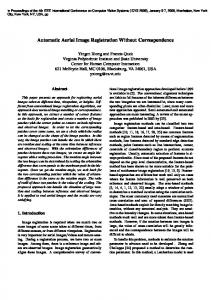
The camera setup used in this paper consists of 35 low cost cameras mounted in a planar circular manner spanning about 130° around the subject to be recorded. The diameter of the camera circle is approximately 2m so that a subject placed in the center of the circle has a recording distance of about 1m to each camera. Figure 1 displays this setup as it has been presented under real-life conditions.
Figure 2: Multi-functional calibration target 4
Since geometrical calibration of the camera array is accomplished by a model-based analysis by synthesis approach, it is mandatory to provide a good and robust initial estimation of the calibration target’s position and orientation. While initialization is often done manually, we have developed a fully automatic initialization routine which relieves the user from annotating one or even several images per camera in our circular camera setup. 4.1
Figure 1: The camera setup The calibration target designed for both geometrical calibration and color calibration of the camera array is cylindrical with a diameter of 40cm and a height of 60cm, designated to cover the spatial range of possible subject placement. Figure 2 displays
Geometrical and Color Calibration
Localization of the Calibration Target
An initial estimation of the target’s position is obtained by inspecting a sparse selection of the image’s columns, one by one, for sets of equidistant and evenly sized vertical windows whose average colors exhibit RGB-ratios similar to the ones of the sought color sequence. These sets are determined by their starting position within the column, the window size and the distance between the windows which amounts to two search parameters when fixing the ratio between window size and distance. We define the RGB-ratio between two windows i and i + 1 as a vector h iT gi gi ri bi ri bi (1) qi = ri+1 gi+1 bi+1 gi bi ri where ri denotes the average red-channel value of window i etc.
ˆ i of The ratio vector qi is now compared to the ratio vector q the respective rows of the target color sequence. If we use a sequence of six colors like with the proposed calibration target, we can provide seven color ratio vectors by including a black stripe above and below the color sequence. In doing so, we even out the fact that the uppermost and lowermost colors are used only once while all others are used twice. Ratio vectors can be compared by summing their absolute elementwise differences ˆi) = d(qi , q
6 X
|qi (k) − qˆi (k)|
(2)
k=1
where qi (k) is the k-th element of vector qi . An objective function for detecting the whole color sequence is given by the sum of the ratio vector comparison values for all color pairs. 7 X ˆi) E= d(qi , q (3) i=1
A minimum in this objective function leads to an initial guess of the vertical position and the stripe height of the color sequence for each inspected column. The image columns which run outside the calibration target can be separated from the others not only by value of the objective function but also by knowledge of the maximal allowable offset of vertical position and stripe height between each column which makes the selection process very robust to noise and false detections of the color sequence. To precisely locate each color transition, the image is filtered for horizontal edges with a [−0.5, 0, 0.5]T -kernel in each color channel. Based on this vertical color gradient image, each pixel is assigned a transition probability for every color transition under consideration. The pathway of the transition is then determined as the horizontal path maximizing the summed transition probability and minimizing vertical offsets between subsequent pixels via dynamic programming. Figure 3 shows the transitions detected by this algorithm as white curves on a slightly pale and dark input image.
Figure 3: Color transitions as detected by the proposed algorithm The precise identification of the left and right borders of the calibration target is achieved by fitting a coarse two-parameter
model (rotation and tilt) of one pixel row of the calibration target to the image along a horizontal path through the white boxes on its surface. This allows to precisely determine the horizontal position of the calibration target in the image, even when it is only partially visible. Since the model consists of only two parameters and a range of possible results for scale and position is known in advance, the model can be fit efficiently via a coarse-to-fine search. To improve performance of the model-based calibration discussed in 4.2, the image is converted to grayscale and a segmentation of the white boxes is performed. We employ a histogram-based sliding-window algorithm which assigns a pixel with intensity no greater than the darkest 10% of pixels in the window an intensity of zero. All pixels with an intensity of at least 0.25 more than that level are assigned full intensity and the intensity of the pixels within this range is stretched linearly to fill the whole intensity domain. A suitable window size is slightly bigger than the biggest depiction of a white box and can be estimated from the known scale of the calibration target in the image. The rotation of the calibration target is estimated by detecting the unique combination of colored boxes visible in the image. To do so, we calculate the error of assigning the color of each of the detected central stripes to each colored box. Effects of illumination and the camera’s color response are minimized by sampling the color of each stripe directly above or below the respective box and inferring the actual color assigned to the box by the index of the color stripe. We then search among the combinations of colored boxes available on the calibration target for the one minimizing the sum of these assignment costs. 4.2
Model-based Geometrical Calibration
For multi-view camera calibration, we exploit an analysis-bysynthesis approach that avoids precise sub-pixel localization of calibration features but exploits the entire image for accurate estimation of intrinsic and extrinsic camera parameters[2]. The method however requires an approximate initialization to prevent it form converging to false local minima in the model fitting process which arise from aliasing of the repetitive white boxes of the calibration target. Utilizing the positions of the colored boxes obtained from the initialization algorithm described in the previous section, a 3D model of the calibration target is fit to the grayscale image also provided by the initialization. As a result, we obtain coarse extrinsic parameters (orientation and position of the body) and infer an initial estimation of intrinsic parameters. This fitting is sufficient for the following algorithm to converge to the correct camera parameters. The geometrical calibration is based on an analysis-bysynthesis framework which matches synthesized frames of the calibration target with the real camera images. For that purpose, the target is represented as a colored, cylindrical 3D model and views are rendered from it using a simple ray tracing technique. Given a set of intrinsic and extrinsic
camera parameters, a corresponding synthetic view is created. From the mismatches of the synthetic image with the real view, parameter updates for intrinsic and extrinsic settings are estimated in a linear hierarchical framework. This optimization is iteratively performed, until a perfect match between real and synthetic image is achieved. Since the perspective camera model which includes parameters for focal length, pixel aspect ratio, principle points and several radial lens distortion values is the same for both rendering and estimation, error accumulation is avoided. Minimization of the mismatch between real and synthetic view is guided by an optical flow-based optimization. The optical flow constraint relates the spatial image gradients and intensity differences between the images to a dense 2D displacement field. Since this constraint is underdetermined with two unknown displacement components for each equation, additional information is required to solve for the displacement field. Instead of adding smoothness priors, we exploit an explicit model of the displacement field being a linearized function of the intrinsic and extrinsic parameter updates. This model contains information about the shape of the calibration target, its position and orientation, as well as the camera settings. Since the model is valid for the entire view showing the object, its combination with the optical flow constraint results in a highly overdetermined set of linear equations which can be efficiently solved by a least squares approach. Problems of limited allowed mismatch between the images and linearization errors are addressed by conducting a Gauss-Newton optimization in a scale space. Thus, highly accurate results are obtained even for rough initial alignment of the images. In order to enhance the precision of the calibration and to cover the entire viewing area of the cameras, multiple images may be captured with the calibration target being placed at different locations. For each additional capture, 6 additional unknown extrinsic parameters for the object position and orientation have to be estimated. The intrinsic parameters, however, are constant for all views of a single camera so that they can be robustly estimated jointly over all available views. Since the total number of unknowns can be large for setups with many cameras and many views, the resulting linear system of equations can also be very large. Due to the sparse structure of this matrix, efficient algorithms for the solution can be used such that only small sub-matrices need to be inverted and stored enabling optimization of large camera arrays in reasonable time. The output of the joint calibration algorithm are the intrinsic parameters for each camera, pose of the calibration target for each capture position as well as position and orientation of all cameras relative to a reference camera. 4.3
Hardware Color Calibration
Camera color calibration is an optimization process in which the nature of the error function as well as the influence of parameter changes are largely unknown. The proposed color calibration method is capable of dealing with individual gains
for red and blue channels and an overall gain, accessible as hardware settings of the cameras. Instead of attempting an absolute calibration of camera color responses such that a certain recorded color is enforced to yield a certain color response, we use the calibration process only to minimize offsets in the color responses between individual cameras and allow the user to choose and set up a primary camera which will not have its settings changed during calibration. Thus, the user is in maximum control of the color response of the whole camera array which is kept consistent by color calibration.
Figure 4: Different color responses of simultaneously triggered cameras using the same camera settings Figure 4 displays some of the possible differences in the color responses of simultaneously triggered cameras each using the same settings that camera color calibration ought to compensate for. As a measure of error between the color responses of different cameras, we compare the colors of the central stripes of our calibration target in the different images. For each stripe, the average color of a small central window within the stripe is extracted, yielding 6 different colors for each image. The error for each gain parameter is obtained by summing the errors for the individual stripes. For the red and blue gain parameters Gr and Gb of a certain camera, this error sum is given by �2 n � 1X rˆk rk Er = − 2 gk + bk gˆk + ˆbk =
1 2
k=1 n X
(4)
k=1 n
Eb
2
(ˆ ρk − ρk )
ˆbk bk − gˆk + rk gk + rk
=
1X 2
=
�2 1 X�ˆ βk − βk 2
k=1 n
!2
(5)
k=1
where rˆk is the red channel of stripe k in the image of the primary camera and gk is the green channel of stripe k in the image of the camera to be calibrated. We use the Greek letters r b ρ and β to substitute for g+b and g+r , respectively.
The intensity error is computed as sum of the individual channel differences n
= =
�2 1 X� (ˆ rk − rk ) + (ˆ gk − gk ) + (ˆbk − bk ) 2 1 2
k=1 n X
2
(ˆιk − ιk )
5.1 (6)
k=1
and is used to measure the error of the overall gain Go . The Greek ι = r + g + b is a substitute for the overall intensity. These error functions are motivated by the expected impact of parameter changes on the color response. Red and blue gains will primarily shift the relation between red or blue and the other two colors, respectively. The overall gain will affect all colors in a similar way. The objective function being minimized is E = Er + Eb + Eo (7) Because the true relation between the input parameters Gr , Gb , Go and the calculation parameters of the error function ρ, β, ι is unknown, we employ a line search algorithm in the space of the calculation parameters to heuristically solve the optimization problem for the input parameters. It seems reasonable to assume at least a quasi-proportional relation between Gr , Gb , Go and ρ, β, ι. Thus, similar to gradient descent methods, we evaluate the error for a configuration of the input parameters pt = [Gr , Gb , Go ]T and try to find a direction dt in parameter space which points towards configurations yielding a lower error. The search direction is inferred from the derivatives of the individual error components with respect to ρ, β and ι: ∂ Er ψc ∂ρ ∂ dt = − ψc ∂β Eb ∂ ψi ∂ι Eo
Along this direction, we search for a configuration pt+1 that actually leads to a lower error. This search is controlled by a single parameter, α and provides hypothetical configurations as (9)
where α is decreased when the hypothesis p∗ does not yield an error reduction and d is recomputed when α undercuts a certain threshold similar to gradient reuse techniques in standard optimization frameworks. 5
Since we do not assume knowledge of inter-camera image correspondences so far, color adaption is calculated and applied globally. This adaption is performed between two images, one source and one target image, and the process is propagated through the camera array starting from the primary camera which the user has set up to the desirable behavior. To this end, a cumulative histogram for each color channel of both images is computed. We consider certain values of each of these histograms, e.g. at 20, 40, 60 and 80 per cent of the maximum image intensity and calculate a smooth gradation function which maps this selection of values in the source image to the corresponding values in the target image.
0
Intensity
1
Figure 5: Example of cumulative histograms of source (gray) and target (black) image. The marked positions will be mapped onto each other by the gradation function.
(8)
where ψc and ψi are constants which ought to capture the proportional component of the relation between input and calculation parameters.
p∗ = pt + αdt
Color Adaption
Occurrences
Eo
a sequence of images that simulates a smooth rotation around the subject, the images must be rectified which is detailed in 5.2.
Color Adaption and Image Rectification
Once the cameras have been calibrated, the actual image data can be recorded and further processed. To improve visual homogeneity of the recorded images, we propose the use of a color adaption algorithm as the one explained here. To achieve
Figure 5 exemplifies the mapping for one color channel of source and target image. The mapping function is a smooth gradation curve which does not change the extreme values (black and white) of an image but the distribution in between. 5.2
Image Rectification
Geometrical camera calibration provides a camera center position ci , an intrinsic parameter matrix Ki and a rotation matrix Ri for each camera i. These form the 3 × 4-projection matrix Pi = Ki Ri [I3 | − ci ] (10) where I3 is the 3 × 3 identity matrix. With ci representing the camera center in the world coordinate frame, the mapping of any point x in this frame onto the image plane of camera i is given by φ2 (x0 ) = Pi φ3 (x) (11) where φk is the homogeneous representation of a point kdimensional space such that � � wx φk (x) = (12) w
has k + 1 dimensions for a k-vector x.
6
To rectify the recorded images using the geometrical calibration data obtained, we render a new view for each camera, thereby virtually changing the viewing direction of the camera such that the principal axes of all cameras precisely meet in one point z in 3D-space. The principal axis (or viewing direction) of a camera is given by
We have proposed a complete setup for the automatic acquisition of 3-dimensional image data and shown its application to automatic recording a smooth sequence with the viewpoint spinning around the subject. Figure 6 shows samples of an image sequence recorded with the low-cost cameras introduced in section 3. All images have been cropped to the same portrait section. It is noticeable that the subject is well-placed in the center in the rectified sequence to the right and that global color adaption has evened out most color discrepancies between the individual images. Alas, since the subject does not expose the same colors and illumination from every viewing angle, a global approach to color adaption is limited to minimizing an imprecise error function.
vi = det(Mi )m3i
(13)
where Mi is a 3 × 3-matrix containing the first three columns of Pi and m3T i is the third row of Mi . To find z, we first estimate the world plane which is closest to the centers and principal axes of all cameras. This principal plane is fit to the center and one point on the principal axis, ci + λvi for each camera by total least squares where we choose λ to be 1m in regard of subject placement in our camera setup. The principal axes of all cameras are then projected onto this plane and z is found as the point minimizing the squared distances to these projections. To change the viewing direction of camera i, we first compute a new rotation matrix Ri∗ = [axi ayi azi ]−1
(14)
Results and Outlook
The number of possible applications and extensions of this setup is manifold. Several approaches to correspondence analysis are being tested at the moment and will offer new possibilities for a correspondence-guided local color adaption. To reduce the number of cameras and generate new views, methods for image interpolation such as in [10] are applied to the data obtained from our setup. Different strategies for the camera setup will be researched as well, especially non-planar layouts are expected to yield advantages for 3Dbased operations. A multi-view consistent segmentation of the subject from the background is also researched at the moment.
with References azi
= z − ci
ayi
= n − (nT azi )azi
axi
= ayi × azi
(15)
where n is the normal of the principal plane obtained above. With this rotation matrix, we can acquire a new projection matrix for each camera by Pi∗ = Ki Ri∗ [I3 | − ci ]
(16)
We transform this projection matrix into the canonical coordinate frame induced by the original projection matrix of camera i by � �−1 Pi ∗ ˆ Pi = P i (17) [0 0 0 1] and finally obtain a 3 × 3-matrix homography between the projected images of both camera matrices by ˆ 2, p ˆ3 − p ˆ 4] Hi = [ˆ p1 , p
(18)
[1] P. Baker and Y. Aloimonos. Complete calibration of a multi-camera network. In OMNIVIS ’00: Proceedings of the IEEE Workshop on Omnidirectional Vision, page 134, Washington, DC, USA, 2000. IEEE Computer Society. [2] P. Eisert. Model-based camera calibration using analysis by synthesis techniques. In Proc. International Workshop on Vision, Modeling, and Visualization, pages 307–314, Erlangen, Germany, Nov. 2002. [3] U. Fecker, M. Barkowsky, and A. Kaup. Improving the prediction efficiency for multi-view video coding using histogram matching. In in Picture Coding Symposium (PCS 2006), 2006. [4] I. Feldmann, M. Mueller, F. Zilly, R. Tanger, K. Mueller, A. Smolic, P. Kauff, and T. Wiegand. HHI test material for 3D video. ISO/IEC JTC1/SC29/WG11 MPEG2008/M15413, April 2008. [5] R. Hartley. Theory and practice of projective rectification. International Journal of Computer Vision, 35(2):115– 127, November 1999.
(19)
[6] R. I. Hartley and A. Zisserman. Multiple View Geometry in Computer Vision. Cambridge University Press, ISBN: 0521540518, second edition, 2004.
Before applying these homographies to the images of the recorded sequence, we compensate the radial lens distortion obtained in 4.2 in each image.
[7] A. Ilie and G. Welch. Ensuring color consistency across multiple cameras. In in ICCV, 2005, pages 1268–1275, 2005.
where ˆ 2, p ˆ 3, p ˆ 4] Pˆi = [ˆ p1 , p
[8] N. Joshi and H. W. Jensen. Color calibration for arrays of inexpensive image sensors. Technical report, Stanford University, 2004. [9] D. Liebowitz and A. Zisserman. Metric rectification for perspective images of planes. In CVPR ’98: Proceedings of the IEEE Computer Society Conference on Computer Vision and Pattern Recognition, pages 482–488, Washington, DC, USA, 1998. IEEE Computer Society. [10] D. Schneider, A. Hilsmann, and P. Eisert. Patch-based reconstruction and rendering of human heads. In Proc. International Conference on Image Processing (ICIP), Hong Kong, Okt. 2010. [11] T. Svoboda, D. Martinec, and T. Pajdla. A convenient multicamera self-calibration for virtual environments. Presence: Teleoper. Virtual Environ., 14(4):407–422, 2005.
Figure 6: Samples of a recorded sequence (left) and corresponding images of the rectified and color-adapted sequence (right).