Available online at www.sciencedirect.com Available online at www.sciencedirect.com
Procedia Engineering
ProcediaProcedia Engineering 00 (2011) 000–000 Engineering 15 (2011) 613 – 617 www.elsevier.com/locate/procedia
Advanced in Control Engineering and Information Science
Automatic Control System of Copper Pipe and Aluminum Pipe Butt Resistance Welding Machine Zhang Yuea, Han Lia, Sun Tailib, Li Qidongb, Zhang Xichuanb a* b
a First affiliation, Address, City and Postcode, Country Second affiliation, Address, City and Postcode, Country
Abstract It becomes a tendency that the application of copper pipe and aluminum pipe welding joints in the field of refrigeration. Based on analysis of Cu-Al pipe welding process, a PLC automatic control system was developed to accurately control the resistance welding machine. The executive mechanism is composed of pneumatic components and controlled by the PLC system to complete the Cu-Al pipe welding process. Under the PLC control, the welding time parameter can be changed, according to the pip size. And the time error of the control system is limited in 0.01s. When the coil temperature rises up to 90℃ or the network voltage fluctuates more than ±10%, the control system alarms the operator and the welding process can not be started.
© 2011 Published by Elsevier Ltd. Open access under CC BY-NC-ND license. Selection and/or peer-review under responsibility of [CEIS 2011] Keywords: Copper pipe; Aluminum pipe; butt resistance welding; programmable logical controller
1. Introduction The competition, in the market economy, leads all the manufactures to cut costs of production. In the refrigeration industry, several years ago, the entire pipeline was produced by cuprum pipe, but now some of manufactures try to employ aluminum pipe in refrigeration pipeline instead of cuprum pipe which is more expensive [1-3]. However, it is difficult to use aluminum pipe entirely, because the cold compressor
* Corresponding author. Tel.: +86-024-2549-6278; fax: +86-024-2549-6278. E-mail address:
[email protected].
1877-7058 © 2011 Published by Elsevier Ltd. Open access under CC BY-NC-ND license. doi:10.1016/j.proeng.2011.08.114
614 2
Zhang Yue et al. / Procedia Engineering 15 (2011) 613 – 617 Zhang Yue, et al/ Procedia Engineering 00 (2011) 000–000
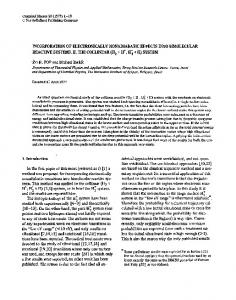
is produced by steel and the welding of aluminum and steel is more difficult than that of cuprum and aluminum or of cuprum and steel. To avoid the difficult of welding, a little segment of cuprum pipe is left to join aluminum pipe and steel pipe in the refrigeration pipeline. Although the Cu-Al joints are usually in the interior of the refrigeration products and customers can’t see them directly, most manufactures pay their attentions to go after the advanced technologies and equipments for Cu-Al pipe (CAP) welding; as they treat other details of their products which will be sell in the market. Recently, there are several methods for Cu-Al pipe welding, such as capacitance energystorage welding, friction welding, flash welding, explosive welding, and so forth [3-6]. These methods are employed in the industrial with different forms. However, their applications are usually under some limitations [3-4]. In the condenser energy-storage welding, a large power capacitance is needed, which is produced or approached with high cost. And in the friction welding, clamping and rotating limits the length and shape of the pipe. In the flash welding, weldments forming effect is under the expectation and weldments must undergo rework. Lastly, in the explosive welding, some dynamite must be located in the pipe before welding, which also limits the length and shape of the pipe. Programmable logical controllers (PLC) have emerged with a wide variety of applications in the manufacturing and automation industry. They are able to meet the flexibility of new control systems. With rapidly declining cost and increasing capabilities, their applications in medium and small machines have become more common. Controlling of executive mechanism motions and welding time parameters is in high accuracy and precision. It is the aim of the present paper to provide a new kind of Cu-Al pipe welder. The main purpose of welder reported here was to achieve welding of cuprum and aluminum pipe in excellent quality. It’s named Cu-Al pipe butt resistance welder controlled by PLC, CAP welder for short in this paper. Compare with those welding principle above, the new Cu-Al pipe butt resistance welder is produced with lower cost, but better performance, and there is few limitation in the production of Cu-Al pipe joints. 2. Structure of CAP welding machine 2.1. Cu-Al pipe welding process Before design the structure of CAP welder, we have to know the process of CAP welding. The Al and Cu pipe we used in experiments and the Cu-Al pipe joint are illustrated in Fig.1. The form of this joint has many excellences, for example the wide combine surface, easy to molding, low cost, and so on. The CAP welding process can be broken down into six steps, as shown in Fig.2.
Fig.1 Copper and aluminium pipe joint
The six steps are: (a) Locating: all the six degrees of freedom of pipes must be limited. One of them is limited by positioning arm. The other five are limited by clamping fixtures. (b) Clamping: a pair of clamping fixture is illustrated in Fig.4. There will be two pairs of clamping fixtures used to clamp Cu pipes and Al pipes in the welder. (c) Feeding: after clamped, Cu pipe will be feed toward Al pipe. When the Cu pipe comes into contact with the Al pipe, the circuit of primary coil of welding transformer will be turned on.
615 3
Zhang Yue name et al. // Procedia – 617 Author Procedia Engineering Engineering 15 00 (2011) (2011) 613 000–000
(d) Welding: a very high current will flow in the circuit of second coil of welding transformer and pipes. The Cu pipe and Al pipe are heated at the same time by the strong current. Stop feeding when the cone of Cu pipe is encased entirely by Al pipe, and then turn down the welding circuit. (e) Loosening: after the temperature of Cu-Al joint falls to some extent, the Cu-Al joint will be loosened. (f) Returning: the executive mechanism will come back to original position and prepare for next welding.
(a) locating
(b) clamping
(c) feeding
(d) welding
(e) holding
(f) pipe joint
Fig. 2. Cu-Al pipe welding process
2.2. Executive mechanism The executive mechanism is composed of pneumatic components, as shown in Fig.3. According to discussing in 2.1, every components of the executive mechanism will work in the given order. All the operations are controlled by PLC. When the Cu pipe and Al pipe are placed on the clamping fixtures manually and keeping the ends of tow pipes touch with positioning piece, tread the foot-switch for enabled instruction, then the process of CAP welding will start.
Fig.3 executive system of Cu-Al pipe butt welder
At first, the solenoid valve PQ1 is turned on, and the clamping cylinders work, then the pipes is clamped. At the same time, the positioning cylinder works, and the positioning piece leaves the welding zone. Secondly, the solenoid valve PQ2 is turned on, while PQ1 continue working. And feeding cylinder works, that is, the right clamping cylinder is feed toward the left clamping cylinder. The feeding velocity is adjusted by a flow regulating valve. The welding transformer begins to work, when the Cu pipe touches with the Al pipe, and the welding starts.
616 4
Zhang Yue et al. / Procedia Engineering 15 (2011) 613 – 617 Zhang Yue, et al/ Procedia Engineering 00 (2011) 000–000
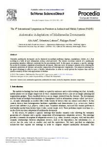
Thirdly, the spacing ring will stop the feeding cylinder and cut down the welding current, and the transformer stop working. After a while, the temperature of Cu-Al pipes joint falls to some extent, then the solenoid valve PQ1 is turned down. Tow clamping cylinders and positioning cylinder drive up. After that, the solenoid valve PQ2 is turned down, and the feeing cylinder returns back. At this time, next welding is ready. 2.3. Self-protection devices All the machines would have the capabilities of self-protection, when they are working. And the CAP welders are protected by some devices, as follows: (1)The temperature of welding transformers will be higher and higher, when welders are working. Cooling water is employed as discusses in 2.2. Before a welder starts to work, a pressure sensor in the cooling tube can know whether there is flowing water in the cooling tube or not. (2)Although there is cooling water, the welding transformers are heated unavoidably. A temperature sensor can know whether the temperature of transformer is too high to continue working or not. (3)The executive mechanism of a CAP welder consists of some pneumatic parts. Consequently, air becomes a medium for power to drive cylinders. The pressure of air must be in the range that cylinders can work normally. A pneumatic sensor is employed to know whether the pressure of air meets requirement of driving cylinders or not. (4)The strength of welding current has effect direct on welding quality of Cu-Al joints. An ampere meter is employed to measure the strength of welding current. If the welding current is so strong that the welding transformers may be damaged, the welding circuit would be turn down. (5)Although there are self-protection devices above, some emergency may take place in welding. In hence, there is a manual emergency brake in the control system. 3. Automatic control system 3.1. Overall design of PLC control system The simplify process of CAP welding is startup – clamping - time delay (t0) – feeding – touch - time delay (t1) - welding – holding (t2)- loosening - time delay (t3) – returning. Because the lengths of air tubes are different, it is time delays that can keep the welding process in the given order. And to save input point, make t0 equal to t3. Based on the points of input and output and costs, a FPI1-C14 PLC made in NAIS, is chose as the nucleus component. The c14 has 8 inputs, 6 outputs and an analog input. 3.2. Program design of PLC There are three parts in the control program of CAP welding machine. They are the programs for selfprotection, time data input, and welding process. And the control flow of CAP welding is shown in Fig.4. The welding machine must work under the conditions discussed above. The program for selfprotection should be considered at first. The welding coil temperature is measured by a thermal couple, and transmitted into PLC. When the coil temperature rises up to 90℃ or the network voltage fluctuates more than ±10%, the control system alarms the operator and the welding process can not be started. In time data input and welding process, three time data’s are needed to be input. The TMR calculagraphes are used with the error of 0.01s, which meets the welding time control requirement. The time data’s are wrote into register with the external analog rheostat of PLC which ranges from 0 to 2.5s.
Zhang Yue name et al. // Procedia – 617 Author Procedia Engineering Engineering 15 00 (2011) (2011) 613 000–000
Fig. 4 the flow diagram of copper pipe and aluminum pipe welding control system
4. Conclusions A PLC automatic control system was developed to accurately control the resistance welding machine, based on analysis of Cu-Al pipe welding process. The executive mechanism is composed of pneumatic components and controlled by the PLC system to complete the Cu-Al pipe welding process. Under the PLC control, the welding time parameter can be changed, according to the pip size. And the time error of the control system is limited in 0.01s. When the coil temperature rises up to 90℃ or the network voltage fluctuates more than ±10%, the control system alarms the operator and the welding process can not be started. The developed automatic control system can produce Cu-Al pipe welding joints in a high pass rate. Acknowledgements This research reported in the paper is financially supported by the Research and Development Plan of the Education Apartment of Liaoning Province (05L301). These supports are greatly acknowledged. References [1] Zhang X C. PLC and TP04G control for UN50 Cu-Al pipe welding machine. J Shenyang Univ Technol 2009;31:173-176 [2] Zhang X C. Compensation control system of Cu-Al pipe welding heat productivity.J Shenyang Univ Technol 2009;31:591595. [3] Zhang Y. Design and Testing of the Copper Pipe and Aluminum Pipe Welding Control System. Appl Mech Mater 2010;33: 84-87. [4] Watanabe T, Sorita H, Sutoh A, et al. Eutectic bonding of Al pipe to Cu pipe.Yosetsu Gakkai Ronbunshu 1998;16:35-44. [5] Oelschlagel D. Ultrasonic soldering method for Copper-Aluminum pipe joints. Welding Journal 1977;56:21-27 [6] Stroiman I M. Cold butt welding of aluminum tubes to copper tubes. Welding Production 1972;7:28-30
617 5