a dataflow graph design space exploration engine heuristically identifies candi- ..... much slower runtime, and thus it was not used in any of the studies in this paper. .... ups when varying communication latency using the set of CFUs developed.
International Journal of Parallel Programming, Vol. 31, No. 6, December 2003 (© 2003)
Automatic Design of Application Specific Instruction Set Extensions through Dataflow Graph Exploration Nathan Clark, 1 , 2 Hongtao Zhong, 1 Wilkin Tang, 1 and Scott Mahlke 1
General-purpose processors are often incapable of achieving the challenging cost, performance, and power demands of high-performance applications. To meet these demands, most systems employ a number of hardware accelerators to off-load the computationally demanding portions of the application. As an alternative to this strategy, we examine customizing the computation capabilities of a processor for a particular application. The processor is extended with hardware in the form of a set of custom function units and instruction set extensions. To effectively identify opportunities for creating custom hardware, a dataflow graph design space exploration engine heuristically identifies candidate computation subgraphs without artificially constraining their size or shape. The engine combines estimates of performance gain, cost, and inherent limitations of the processor to grow candidate graphs in profitable directions while pruning unprofitable paths. This paper describes the dataflow graph exploration engine and evaluates its effectiveness across a set of embedded applications. KEY WORDS: Application-specific processor; dataflow graph; embedded system; hardware customization; instruction set.
1. INTRODUCTION In recent years, the markets for PDAs, cellular phones, digital cameras, network routers, and other high performance but special-purpose devices 1
Advanced Computer Architecture Laboratory, University of Michigan, Ann Arbor, Michigan 48109. E-mail: {ntclark, hongtaoz, tangw, mahlke}@umich.edu 2 To whom correspondence should be addressed. 429 0885-7458/03/1200-0429/0 © 2003 Plenum Publishing Corporation
430
Clark, Zhong, Tang, and Mahlke
has grown explosively. Many of these devices perform computationally demanding processing of images, sound, video, or packet streams. In these systems, application specific hardware design is used to meet the challenging cost, performance, and power demands. The most popular design strategy is to build a system consisting of a number of special-purpose application-specific integrated circuits (ASICs) coupled with a low cost core processor, such as an ARM processor. (1) The ASICs are specially designed hardware accelerators to execute the computationally demanding portions of the application that would run too slowly if implemented on the core processor. While this approach is effective, ASICs are costly to design and offer only a hardwired solution that permits no postprogrammibility. An alternative design strategy is to augment the core processor with special-purpose hardware to increase its computational capabilities in a cost effective manner. The instruction set of the core processor is extended to feature an additional set of operations. Hardware support is added to execute these operations in the form of new function units or co-processor subsystems. There are a couple of benefits to this approach. First, the system is postprogrammable and can tolerate changes to the application. Though the degree of application change is not arbitrary, the intent is the customized processor should achieve similar performance levels with modest changes to the application, such as bug fixes or incremental modifications to a standard. Second, some or all of the ASICs become unnecessary if the augmented core can achieve the desired level of performance. This lowers the cost of the system and the overall design time. The key questions with this approach are whether the augmented core can achieve the desired level of performance and how to design an efficient set of extensions for the processor core. For this paper, we focus on the goal of defining a set of instruction set extensions to accelerate a target application in a cost-effective manner. This process can be as time consuming and expensive as designing an ASIC if done manually, thus we believe automation is a key to making this strategy successful. Our approach is to use a dataflow graph exploration engine to identify the critical computation subgraphs in the target application. The subgraphs are analyzed to determine the desirability of using specialized hardware to accelerate them. A number of issues must be considered to determine desirability, including estimated performance gain, estimated cost of the custom hardware, encoding of the new operation in the core processors instruction format, and expected usability of the custom hardware. With this data in place, a set of hardware extensions to processor are selected and a compiler generates code with the selected subgraphs replaced by new instructions.
Automatic Design of Application Specific Instruction Set Extensions
431
There are three contributions of this paper. First, we describe and categorize the issues associated with adding custom hardware to a core processor. Next, we propose a novel dataflow graph exploration heuristic to efficiently determine which computation subgraphs are the best candidates for hardware extensions. Our heuristic is applied to several benchmarks in order to determine its effectiveness. Finally, the effect of communication latency to and from the custom hardware is explored. 2. DATAFLOW GRAPH EXPLORATION The overall structure of the dataflow graph exploration engine is shown in Fig. 1. An application is fed into the system as profiled assembly code. The code has not been scheduled and has not passed through register allocation, which is important so that false dependences within the dataflow graph are not created. Initially, the application passes through a dataflow graph (DFG) space explorer, which determines candidate subgraphs for potential instruction set extensions. The space explorer selects subgraphs subject to some externally defined constraints such as the maximum die area allowed for any custom function unit (CFU), or the maximum allowable register read and write ports. A hardware library provides timing and area numbers to the space explorer so that it can accurately gauge the cycle time and area requirements of combined primitive operations. The hardware library was created by synthesizing primitive operations with Synopsis design tools and a popular 0.18m standard cell library. A list of subgraphs, annotated with area and timing estimates, is passed to a candidate combination stage. This stage groups subgraphs that would be executed on the same piece of hardware. Grouping the subgraphs creates a set of candidate CFUs and allows us to calculate an estimate of External Constraints - I/O, Total cost
App i Optimized, unscheduled,, unallocated assembly code
Dataflow Graph Spac e Explorer
Candidate Combination Candidate a Subgraphs
CFU selector id t Candidate CFUs
HWLib Li (opcode× width× freq)
Fig. 1. Organizational structure of the DFG exploration engine.
Prioritized List of CFUs
432
A.
Clark, Zhong, Tang, and Mahlke
1
+
2
4 AND
LD
B.
3 LD
5 XOR
6 XOR
7
+
8
+
10
+
17
23
>> +
m ^= p [0]; r ^= p[ 1]; r ^= (((s[(m>>24L)] + s[0x0100+((m>>16L)&0xff)]) ^ s[0x0200 + ((m>> 8L)&0xff)]) + s[0x0300+((m )&0xff)]) & 0xffffffff; m ^= p[ 2]; m ^= (((s[(r>>24L)] + s[0x0100+((r>>16L)&0xff)]) ^ s[0x0200+((r>> 8L)&0xff)]) + s[0x0300+((r )&0xff)]) & 0xffffffff; Opcode
Area
Cycles
+
1.0
0.30
AND
0.12
0.06
*
0.01
~0
XOR
0.16
0.09
* These are shifts by compile time constants
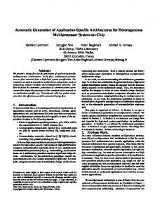
Fig. 2. (A) Sample dataflow graph from the blowfish benchmark. Bold arrows indicate the critical path, and the shaded nodes delineate a CFU discovered by the explorer. An internal node with only one input edge signifies that the other operand is a constant. (B) Part of the preprocessed C code from blowfish that this DFG came from. (C) Excerpt of the data from the hardware library. Areas are relative to a 32 bit carry-lookahead adder and cycle calculations are based on a 300 MHz clock.
performance gain by using the profile weights of all the set members. The combination stage also performs some checks to determine which CFUs can potentially be subsumed by other CFUs. All of this information is passed to a selection mechanism that determines which CFUs best meet the needs of this application. Throughout this section, the DFG shown in Fig. 2 from the blowfish application (2) is used for illustrative purposes. For simplicity, each operation or node is assumed to take 1 cycle to execute in the baseline processor. 2.1. Dataflow Graph Exploration A CFU is loosely defined as the hardware implementation of a subset of primitive operations from an application’s DFG. Primitive operations are atomic assembly operations for a generic RISC architecture, such as Add, Or, and Load. These operations correspond to nodes in the DFG. No assumptions are made regarding the connectivity of the nodes in a CFU, so
Automatic Design of Application Specific Instruction Set Extensions
433
linear, tree shaped, or even cyclic graphs can be implemented as CFUs. In this work we consider only connected subgraphs. Implementing subsets of the DFG in hardware, as CFUs, typically allows for better performance, lower power consumption, and reduced code size than the corresponding implementation as a sequence of primitive operations. Determining which parts of a DFG would make the best CFUs is clearly a very difficult problem. The most glaring difficulty is that there are an exponential number of potential candidates to select as CFUs for a given DFG. In the most general sense, each node of the DFG can either be included or excluded from a candidate, yielding O(2 # ops ) potential candidates. The DFG exploration proposed here is a novel algorithm to effectively curve the exponential growth of this problem. Exploration starts by examining each node in the DFG and using it as a seed for a candidate subgraph. Initially, the technique used a naı¨ve implementation that looked at all possible directions to grow the seed nodes and then added pairs of nodes (the seed plus a node in one growth direction) to a list of potential candidates. Next, these pairs were used as seeds, and candidates of size three were grown from the dataflow edges entering and leaving the candidates. The algorithm recursed until certain external constraints were met, for example the resultant candidate could not grow without crossing a function call or the die area of the resultant candidate was too large. The number of candidate subgraphs quickly grows out of control with sufficiently loose external constraints, preventing the algorithm from completing on most MediaBench (3) applications. Empirical experiments showed that running the algorithm with tight external constraints produced very poor quality candidates, as it unnecessarily restricted the discovered candidates. The key observation gained from experimenting with this naı¨ve approach is that the majority of candidates examined by exponential growth simply do not make sense. For example, assuming the goal is maximizing performance on the DFG in Fig. 2, CFU 6-10 has little value, because node 10 is not on the critical path. To avoid searching these useless candidates, we propose using a guide function to rank which nodes are the best directions to grow in. The guide function allows heuristic determination of the merit of each growth direction, and arbitrary control on the fanout from seeds. Allowing a larger number of candidates from each seed, or large fanout, will ensure better coverage of the design space, while allowing smaller fanout will result in reduced run times and memory consumption. One important part of our technique is that restricting fanout enables more efficient design space exploration. For example, higher fanout could be used in blocks that have higher profile weight, as they are more likely to
434
Clark, Zhong, Tang, and Mahlke
yield important candidates; alternately, higher fanout could be used at the initial levels of the search and then more tightly constrain the number of growth directions as the candidates increase in size. Flexibility is one of the major benefits of this technique. All previously proposed solutions use a single exploration strategy for all parts of the application, where as this technique can modify its strategy to effectively avoid searching likely useless portions of the design space. 2.2. Guide Function The purpose of the guide function is to intelligently rank which growth directions will create the best candidates. The guide function is essentially trying to replace the architect by making design decisions, thus its decisions must reflect the same desirable properties the architect would strive for. The guide function proposed here uses four categories to rank the desirability of growth directions: criticality, latency, area, and input/output. Giving each of these categories different weights toward the overall score of the guide function will greatly affect the types of candidates that are generated. Many experiments have been performed varying the weights of each of these factors and they point to the conclusion that, generally speaking, evenly balancing the factors yields the best candidates. In the DFG space explorer, each of the guide function categories is allotted 10 points of weight, and the sum of these categories determines the total desirability of each candidate direction. If a direction receives fewer than half of the total desirability points, then it is considered a bad direction and it will not be explored. This is not to say that half of the directions will be ignored, merely that directions with less than half of the points are not worth investigating. Criticality. This category rewards candidate directions when they appear on the critical path (longest dependence path(s)) of a DFG. CFUs that occur on the critical path are likely to give the application performance improvement, which is typically the most desired result of CFUs. An example of this from Fig. 2 would be investigating ways to grow candidate 4-6. The direction including nodes 1, 7, or 8 would rank higher in terms of criticality than would the direction of nodes 5, 9, or 10, because the aforementioned nodes are on the critical path. Points are awarded using the 10 equation slack+1 , where slack is the number of cycles an operation can be delayed without lengthening the critical path. Thus, node 1 would get 10 10 =10 points and node 10 would get 2+1 =3.33 points. 0+1 Experiments have shown that it is important to give candidate directions credit even when they lie slightly off the critical path. This is because
Automatic Design of Application Specific Instruction Set Extensions
435
in several instances replacing some nodes on the critical path can expose an auxiliary critical path in the DFG. For example, if we selected a CFU for nodes 7-11-14-18 and 8-12-15-19 in Fig. 2 then nodes 9, 13, 16, and 22 would become a new critical path. Giving candidates that grow in these directions some credit keeps them available for selection, even if they do not initially appear useful. Latency. Latency tries to guide exploration towards combining operations which require fewer cycles to execute when combined into a CFU than they do as stand-alone operations. The largest performance gains are possible by combining low latency operations, such as logicals, where many can be executed in a single cycle. Latency points are distribold latency uted using the equation new latency f 10. The latency of a CFU is calculated by summing up the fractional delays of each atomic operation (see Fig. 2c) along the critical path of the candidate subgraph. Using candidate 4-6 on Fig. 2 as an example again, note that currently these operations can be executed back to back in 0.15 cycles. Exploring the direction of node 1, 0.15 f 10=3.33 points. In which has a latency of 0.3 cycles, would get 0.15+0.30 0.15 contrast, growing towards node 10 would get all ( 0.15+0 f 10=10) the points allotted for latency. Area. Since cost is a major constraint in the design of embedded processors, area is an important factor in the choice of CFUs. This metric should factor in the area of the CFU, the additional inter-connect and control logic, and the impact on decode logic to the core processor. Register file ports are considered a design constraint and will never be added to support a custom instruction, so they do not factor into the area. It is difficult to measure the impact on decode and control logic, and so the simplifying assumption is made that CFU area is the dominant term. The guide function considers area to be the sum of the cost of each primitive operation in the CFU (see Fig. 2c). The area category gives more points to directions that least increase the total area of the candidate. Area points are calculated the same way as old area latency, new area f 10, except that the old and new areas are rounded up to the nearest half adder (that is a cost of 0.49 or 0.01 adders becomes 0.5). Rounding is done so as not to penalize operations unfairly when the seed is too small. Consider the case of growing candidate 10-17. If no rounding was done, then growing to node 23 would only yield 0.02 f 10 points and 1.02 f 10 points. This does not mean that growing to node 6 would only yield 0.02 0.18 growing toward node 6 is bad decision from an area standpoint, however. Input/Output. The maximum number of input/output operands allowed for a CFU is limited. Register file ports are generally fixed on the
436
Clark, Zhong, Tang, and Mahlke
core processor based on cost, power, and cycle time constraints. Further, instructions for a CFU that has too many operands may not be encodable in a conventional instruction set. Thus, the maximum number of input and output operands available is treated as design constraint, meaning any candidates that exceed the prescribed limits are discarded. The purpose of the I/O category is to guide the search in directions that reduce or keep constant the number of inputs and outputs to the candidate. Giving preference to directions that do not increase I/O facilitates discovering larger subgraphs that still meet I/O constraints. Points are awarded based on the number of input and output ports using the equation old # ports min( new f 10, 10). Taking the minimum of the two terms in the equa# ports tion is done because the number of ports may be reduced by growing certain directions due to reconvergence points in the DFG. As an example of this calculation, if directions from candidate 8-12 from Fig. 2 were examined, growing toward node 15 would not increase the number of 2 inputs or outputs, yielding 2+1 f 10=6.67 points. Growing towards node 6 would actually increase both the number of inputs and outputs, though, 2 f 10=4 points. yielding 4+1 One issue not considered by the current guide function is power consumption. As with performance, CFU candidates can be favored that best reduce power by enabling more efficient implementation of the candidate DFG by using custom hardware. The extension of the guide function is relatively straight forward and is the subject of future work. With the guide function heuristic in place, it was important to verify two points: first that the heuristic does indeed prune the search space, and second that good candidates are not missed because the guide function incorrectly dismisses them. Figure 3 demonstrates the first point. The intelligent heuristic is able to effectively curve the exponential growth associated with the DFG exploration problem. This algorithm can be used on very large code segments and without artificially constraining the types of candidates generated, which are both weaknesses of previously proposed algorithms. To ensure that good candidates are not dismissed, the heuristic was compared against a full exponential search for several small benchmarks. The results showed that both approaches selected identical sets of candidates. The heuristic was also compared against full exponential search using restricted constraints (3 input, 2 output ports and a five adder maximum cost) on many larger benchmarks. Again, the results found using the heuristic were comparable with those of full exponential search. 2.3. Candidate Combination Once candidate subgraphs are discovered, it is a fairly straight forward process to group identical ones together into candidate CFUs. A simple
Automatic Design of Application Specific Instruction Set Extensions
437
100000000
Number of Candidates Examined
Intelligent
All Paths
10000000
1000000
100000
10000 0
1
2
3
4
5
6
Cost Constraint (Adders) Fig. 3. Comparison of the number of candidates examined by the intelligent heuristic compared with growth in all available directions on blowfish. The X-axis shows the maximum die area the candidates were allowed to grow to. There are no points at costs four and five for ‘‘all paths’’ because we did not have access to a machine with enough memory to run the experiment.
test checking graph equivalence, while taking into account commutativity, accomplishes this. For example, if subgraphs 7-11-14-18 and 8-12-15-19 were discovered in Fig. 2, the graphs would be checked for equivalence and then combined into the candidate CFU ‘‘.’’ The profile weights are then used to get an estimation of the number of cycles each CFU improves performance. Using a compiler instruction scheduler to get an exact measurement is possible, but the complexity makes this solution undesirable. Investigation has shown that performance estimates based solely on the dynamic number of occurrences of each subgraph prove reasonably accurate. After candidate grouping, there are two passes over the list of CFUs. The first pass records which CFUs can be subsumed by others. Subsumed subgraphs take advantage of the fact that most atomic operations have an associated identity input, allowing values to pass through a node without changing. Using Fig. 2 as an example, if CFU ‘‘AND-ADD->>’’ was discovered, CFU ‘‘AND->>’’ can be executed on the same hardware because the subsumed hardware could set one input of the ADD operation to zero. CFUs ‘‘AND-ADD’’ and ‘‘ADD->>’’ would also be recorded as being subsumed by ‘‘AND-ADD->>.’’ Recording which CFUs are subsumed
438
Clark, Zhong, Tang, and Mahlke
by others proves useful for value and cost estimation done by the selection heuristic described later. The second pass records a single wildcard option for each CFU. Wildcards are defined as CFUs with identical subgraphs except for different operations at one node. Combining two CFUs with similar structure like this allows us to cheaply add another CFU without greatly increasing the associated cost, as much of the hardware can be shared between the two CFUs. Many CFUs could potentially be wildcard matches for each other, but for simplicity only the wildcard match with the best estimated cycle savings is recorded for each CFU. 2.4. Candidate Selection Contrary to combining the candidate subgraphs, CFU selection is not straight forward. Selection is very similar to the 0/1 knapsack problem. There is a set of resources (the candidate CFUs) which all have values (the estimated cycle savings) and weights (the cost in die area), and the goal is to maximize the total value for a given weight threshold. It is widely known that the 0/1 knapsack problem is NP-complete, although it is solvable in pseudo-polynomial time using dynamic programming. Strategies are needed to avoid intractability in this stage of design automation as well. It is important to mention that CFU selection has one caveat missing in the 0/1 knapsack problem: the values of all the other CFUs change once a CFU is selected for inclusion. Individual operations can appear in multiple subgraphs and thus multiple CFU candidates. Once a CFU is selected, it is necessary to update the estimated cycle savings of the other CFUs so that double counting does not occur. Using an example from Fig. 2 again, assume the two highest ranked CFUs were 7-11-14-18, and 7-11-14. If 7-1114-18 was selected first and did not update the value of 7-11-14 to reflect the fact that it can no longer use any of its operations, then 7-11-14 would be selected also, even though it would provide no gain above what 7-1114-18 already provided. The strategy used for CFU selection is a simple greedy method, illustrated in Fig. 4. Given a list of CFU candidates, the one with the best ratio of value is greedily selected (note best value alone is also a valid heuristic). cost Once a CFU is selected (number 2 in this example), the heuristic iterates through the list of remaining CFU candidates and removes operations that were already claimed by CFU 2. The estimated performance gain attributed to each operation is kept track of to make updating statistics easy. In Fig. 4 operations 1 and 7 were removed from CFU N and its value was updated to 0, as it had no more operations left. Operation 3 was removed from CFU 1 and its value was likewise updated to 16, taking into
Automatic Design of Application Specific Instruction Set Extensions Greedily select CFU 2 – the one with the best value/cost
439
Update the values of each CFU that depended on ops that are now attributed to CFU 2
Cost
Ops
CFU Number
Value
Cost
Ops
CFU Number
Value
Cost
Ops
20
4
3,4,8,6,9
1
20
4
3,4,8,6,9
1
16
4
4,8,6,9
6
1
1,3,7
2
6
1
1,3,7
2
6
1
1,3,7
…
…
…
…
…
…
…
…
…
…
…
…
N
8
5
1,7
N
8
5
1,7
N
0
5
CFU Number
Value
1 2
Add CFU 2 to the final list, remove CFUs with no value, and repeat until we exceed our area budget
Fig. 4. Basic greedy approach to CFU selection.
account that it can no longer use operation 3. Once all CFUs are updated, the selection process is repeated until the area budget is exhausted. Custom instruction replacement in the compiler happens in the same order that CFUs are selected, so iteratively updating the values by invalidating selected operations maintains the relative accuracy of the cycle gain estimations. Because the selection heuristic is greedy, it is not guaranteed to give an optimal solution, and quite frequently it does not. For example, when the greedy algorithm selects based only on cycle savings, performance does poorly at the low cost budget points compared to when it selects based on cycle savings . The opposite is true at the high cost points, however. In an cost attempt to improve the selection heuristic, a version based on the optimal dynamic programming solution to the 0/1 knapsack problem was implemented. The dynamic programming heuristic generally does better (roughly 5–10% on average) than both greedy solutions, however it suffers from a much slower runtime, and thus it was not used in any of the studies in this paper. Though the dynamic programming method provides better results, it is still not necessarily optimal as its decisions are based on cycle gain estimations and it has to make local decisions without knowing how one selection will affect later selections. Dealing with wildcards and subsumed subgraphs adds another challenge to the selection process. The main issue is whether to count all the subsumed subgraphs and wildcards when determining the estimated value of a CFU. If so, then in addition to updating the estimated value of other CFUs based on the operations in the candidate subgraphs, it is also necessary to update them based on all the operations in their subsumed or wildcard candidate subgraphs. This creates a huge computational overhead for every CFU selection. In the case of subsumed subgraphs, this often means frequently attributing operations to small subsumed portions of a large CFU, when much more performance could have been gained by attributing
440
Clark, Zhong, Tang, and Mahlke
them to a separate CFU. For example, if the gray shaded CFU in Fig. 2 was selected then it would be possible to execute 13-16 together on the gray CFU, as 13-16 is subsumed. However if a CFU for 13-16-22 could have been chosen later, that would have helped performance more, but this option has been precluded because operations 13-16 have already been claimed by the large gray CFU. The case just described occurs quite frequently, so subsumed subgraphs and wildcard candidates are not included in our performance estimations. Instead CFUs are selected as if they had no subsumed subgraphs or wildcards, and then the costs of the subsumed subgraphs and wildcards are updated to reflect the fact that they can now be selected for very little cost overhead. Another issue to consider is the possibility that implementing a subsumed subgraph as a separate CFU is more desirable than implementing it on existing, subsuming hardware. As an example consider the large gray CFU from Fig. 2. If ‘‘XOR-