propose a graphical user interface(GUI) DSE framework for .... âsource nodeâ, u0, to which there are no incoming edges. ...... R. P. Nix, J. S. O'Donnell, and .
IEEE TRANSACTIONS ON COMPUTER-AIDED DESIGN OF INTEGRATED CIRCUITS AND SYSTEMS
1
Automatic Design Space Exploration of Register Bypasses in Embedded Processors Aviral Shrivastava, Member, IEEE, Sanghyun Park, Student Member, IEEE, Eugene Earlie, Nikil Dutt, Member, IEEE, Alex Nicolau, Member, IEEE, and Yunheung Paek, Member, IEEE
I. A BSTRACT Register Bypassing is a popular and powerful architectural feature to improve processor performance in pipelined processors by eliminating certain data hazards. However, extensive bypassing comes with a significant impact on cycle time, area and power consumption of the processor. Recent research therefore advocates the use of partial bypassing in processor. However, accurate performance evaluation of partially bypassed processors is still a challenge; primarily due to the lack of bypass-sensitive retargetable compilation techniques. No existing partial bypass exploration framework estimates the power and area overhead of partial bypassing. As a result the designers end up making sub-optimal design decisions during the exploration of partial bypass design space. This article presents PBExplore: An automatic design space exploration framework for register bypasses. PBExplore accurately evaluates the performance of a partially bypassed processor using a bypass-sensitive compilation technique. It synthesizes the bypass control logic and estimates the area and energy overhead of each bypass configuration. PBExplore is thus able to effectively perform multi-dimensional exploration of the partial bypass design space. We present experimental results of benchmarks from the MiBench suite on the Intel XScale architecture on and demonstrate the need, utility and exploration capabilities of PBExplore. Index Terms— Operation Table, Partial bypassing, bypasses, forwarding path, processor pipeline, partially bypassed processor, pipeline hazard detection
II. I NTRODUCTION Bypasses, or forwarding paths are simple yet powerful and widely used feature in modern processors to eliminate some data hazards [1]. With Bypasses, additional datapaths and control logic are added to the processor so that the result of an operation is available for subsequent dependent operations even before it is written in the register file. However, this benefit of bypassing is accompanied by significant impact on the wiring area and complexity on the chip, possibly widening the pitch of the execution-unit datapaths. Datapaths including the bypasses often are timing critical and cause pressure on cycle time, especially the single cycle paths. The delay of bypass logic can be significant for wide issue machines, forcing the designers to choose more low Vt transistors, increase transistor sizing, or use other more energy-hungry design styles like dynamic logic to meet cycle time. Due to extensive bypassing very wide multiplexors or buses with several drivers may be needed. Thus complete bypassing may Aviral Shrivastava is an Assistant Professor at the Arizona State University. Sanghyun Park and Yunheung Paek (correspondings) are at the Seoul National University, Korea.
have a significant impact in terms of area, cycle time, power consumption, and wiring complexity of the processor [2]. Embedded systems are characterized by strict multidimensional design constraints, e.g. power, performance, complexity, time-to-market etc. To meet all the design constraints simultaneously, embedded processor designers seek trade-offs between these design metrics. Partial Bypassing presents one such important trade-off that embedded processor designers want to explore. A partially bypassed processor has only some of the possible bypasses. pipeline path data path
F Fig. 1.
D
RF
OR
EX
WB
A fully bypassed processor pipeline
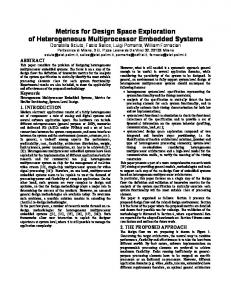
Figure 1 depicts a fully bypassed processor. It has bypasses from both the EX (Execution) pipeline stage and the WB (Writeback) pipeline stage to both the operands of the OR (Operand Read) pipeline stage. Bypass paths from the WB pipeline stage to the OR pipeline stage are needed if the reads in the RF (Register File) happen before the writes to the RF in a cycle. pipeline path data path
F Fig. 2.
D
RF
OR
EX
WB
A partially bypassed processor pipeline
Figure 2 depicts a partially bypassed processor, where the result of the EX pipeline stage can be bypassed only to the second operand, and the result of the WB pipeline stage can be bypassed only to the first operand in the OR pipeline stage. Although a partially bypassed processor cannot have better performance than a fully bypassed processor, the problem is to find the bypass configuration that results in the best power-performance trade-off. Thus a Design Space Exploration (DSE) is required over the bypass design space.
IEEE TRANSACTIONS ON COMPUTER-AIDED DESIGN OF INTEGRATED CIRCUITS AND SYSTEMS
Bypass Configuration
Application
Fig. 3.
Compiler
Executable
Simulator
Power Performance
Traditional Simulation-Only (SO) Exploration of Bypasses
Figure 3 depicts the traditional method of exploring the design space of bypasses in embedded processors. In the traditional methodology, the application is compiled once, and the executable (binary) is generated. The executable is then simulated on cycle-accurate processor models with different bypass configurations. For each bypass configuration, the power, performance etc. is estimated. The bypass configuration which fares the best as per the design constraints is chosen. We call such traditional exploration methodology as SimulationOnly (SO) bypass exploration methodology. The processor is then manufactured with the selected bypass configuration. Although there exist no published mechanisms for bypass-sensitive code generation, ad-hoc scheduling rules may be used to generate code for the processor, and exploit the bypass configuration. e.g., for the processor pipeline shown in Figure 2, a scheduling rule - if the dependent operation needs the result of an operation as the second operand, then they should be separated by one cycle, or 3 or more cycles; otherwise they should be separated by 2 or more cycles - can exploit the bypass configuration. This is an example of bypass-sensitive operation scheduling approach. Shrivastava et al. [3], [4] shows that bypass-sensitive compiler can generate on average 8% and up to 20% better performing code than the best bypass-oblivious compiler. Given that the compiler significantly affects the performance evaluation of a bypass configuration, compiler effects should be included while deciding the bypass configuration of the processor. This article presents a systematic methodology to include the compiler effects during bypass design space exploration. Processor Description Bypass Configuration
AutoOT
Application
Fig. 4.
Compiler
Executable
Simulator
Power Performance
Compiler-in-the-Loop (CIL) Exploration of Bypasses
Our approach, PBExplore, which is depicted in Figure 4 is a Compiler-in-the-Loop DSE methodology to explore the bypasses design space in embedded processors. In the CIL DSE, the application is compiled for a given bypass configuration. The generated binary is then simulated on the processor model with the same bypass configuration to estimate the power consumption and the performance. Given that the compiler will be the code generator for the processor, CIL DSE can accurately and meaningfully explore the bypass design space.
2
CIL DSE methodology requires a bypass-sensitive compiler [5]. A bypass sensitive compiler needs to be able to detect all pipeline hazards that may occur during execution of a schedule of instructions. In order to do this, the bypass-sensitive compiler must know the structure of the pipeline, the flow of operations in the pipeline, and the bypasses present/absent in the pipeline. Shrivastava et al. [3], [4] proposed the concept of Operation Table (OT) to provide this processor architecture information to the compiler. An OT is a data structure that unifies the information of an operation with the pipeline connectivity information of the processor. Each operation has an OT, and the compiler can combine the OTs of the operations in a given schedule to accurately detect all kinds of pipeline hazards (data hazards and resource hazards). This ability of accurately detecting all pipeline hazards in a given schedule, enables scheduling techniques to find out the best schedule. In PBExplore, our CIL DSE framework, we describe the processor architecture in EXPRESSION, our high-level processor Architecture Description Language (ADL). AutoOT interprets the processor architecture and generates OTs for the compiler [6]. The compiler uses the OTs and performs bypasssensitive operation scheduling. III. R ELATED W ORK A. Partial Bypassing Bypassing was first described in the IBM Stretch [7]. Modern processors heavily use bypasses to avoid data hazards and thereby improve performance. And some recent works propose the techniques to reduce the power in the processors. Park et al. [8] proposed a technique to reduce the register file power consumption by scheduling instructions so that they transfer the operands via bypasses, rather than reading from the register file. Sami et al. [9] showed that a significant number of variables are short-lived. They demonstrated that the value of the short-lived variables can be directly bypassed, avoiding write back to the register file in VLIW architectures. However, [8] and [9] do not consider the significant effect of full bypassing on area and energy cost. Cohn et al. [10] showed that partial bypassing helps reduce cost with negligible reduction in the performance on the iWarp VLIW processor. Abnous et al. [11], [12] analyzed partial bypassing between VLIW functional units in their 4-integer-unit VIPER processor. They argued that complete bypassing is too costly in VLIW processors even though the performance benefits are achieved. B. Compiling for partial bypasses Ahuja et al. [2] discuss the performance and cost trade-off of register bypasses in a RISC-like processor. They manually performed bypass sensitive compilation (operation reordering) on a few benchmarks, and presented results with a relatively coarse cache model. Buss et al. [13] reduce inter-cluster copy operations by placing operand chains into the same cluster and assigning FUs to clusters such that the inter-cluster communication is minimized. The work closest to ours is by Fan et al. [14], in which they propose a scheme to prioritize the Functional Units (FUs), so
IEEE TRANSACTIONS ON COMPUTER-AIDED DESIGN OF INTEGRATED CIRCUITS AND SYSTEMS
as to reuse the bypasses, and reduce the number of bypasses needed in a wide VLIW-style architecture. Our work differs from their work in several key ways: i) Our approach is for instruction re-ordering, while their’s is operation-to-FU binding mechanism. Thus both these techniques could be be applicable together. ii) Their technique is applicable for statically scheduled processors, i.e., VLIW-style processors, while ours is for a dynamically scheduled processor, specifically, processors with register scoreboarding. iii) their technique is applicable to processor pipelines in which the bypasses are at most 1-deep (which is typically the case in VLIW machines), while we allow any kind of bypass network (which can be the case in dynamically scheduled processors,) and finally iv) their approach considers the area and performance overheads of the bypass configuration, while we consider the power consumption of the bypass configuration in addition. The concept of Operation Tables (OTs) proposed in this article is similar to Reservation Tables (RTs). Reservation Tables (RTs) [15] or Finite State Automata [16], [17] (generated from Reservation Tables) are used to detect resource hazards in retargetable compiler frameworks [18], [19], [20], [21]. RTs model the structure of the processor including the pipeline of the processor and the flow of operations in the pipeline. RTs can thus be used to model resource hazards in a given schedule. However RTs do not model data in the schedule and are thus unable to detect data hazards. Whereas Operation Tables model both the resources and the register information of operations so that both data and resource hazards can be effectively captured [3], [4]. Furthermore, RTs suffer from modeling the complex features of modern processors such as micro-operation (e.g. load-multiple), partial bypassing .etc. C. Architecture Description Language Architecture Description Language (ADL) is a language used to describe software and hardware architectures. Computer architects have long used machine description languages for the specification of architectures. Early ADLs such as ISPS [22] were used for the simulation, evaluation, and synthesis of computers and other digital systems. Contemporary ADLs can be classified into three categories based on the nature of the information an ADL can capture: structural, behavioral, and mixed. Structural ADLs (e.g., MIMOLA [23]) capture the structure in terms of architectural components and their connectivity. Behavioral ADLs (e.g., nML [24] and ISDL [25]) capture the instruction set behavior of the processor architecture. Mixed ADLs (e.g., LISA [26] and EXPRESSION [20]) capture both the structure and behavior of the architecture. There are many comprehensive ADL surveys available in the literature, including ADLs for retargetable compilation [27], SOC design [28], and programmable embedded systems [29]. Additionally, several commercial offerings following this ADL approach are now available, for example, Tensilica [30] and LISATek (http://www.coware.com). D. ADL-based Design Space Exploration Several approaches have been proposed for DSE using ADLs. Halambi et al. [20] proposed DSE framework using
3
EXPRESSION ADL to support fast iteration through the design cycles of complex System-on-Chip (SOC). They vary the processor parameters like the number of functional units, register files etc. They also change the instruction set by adding or removing operations. These changes are easily specified in their EXPRESSION, and EXPRESSION enables efficient DSE. In [31] the authors proposed DSE framework for reduced bit-width Instruction Set Architecture (rISA) [32] extension to improve code density of RISC processors. A various rISA parameters are specified in EXPRESSION and used by the retargetable compiler and the simulator. Zabel et al. [33] presented a parameterizable template model of the DSP architecture based on a standard ARM7 RISC microprocessor. They use their own ADL and simulation environment, and explore the DSP design space such as the ALU array geometry, memory transfer bandwidth and the number of configuration context. Fisher et al. [34] used MAML (MAchine Markup Language) to describe the architecture parameters for DSE. They describe pipelined microarchitectures with MAML, and explore the design space such as the number and types of functional units, the number of register banks, bus, .etc. Pasricha et al. [35] propose a graphical user interface(GUI) DSE framework for memory exploration. They describe the architecture using the GUI and ADL specification is generated automatically allowing fast modification of memory hierarchies and cache parameters. All the works described above emphasized that ADLs are essential for efficient DSE. E. Compiler-in-the-Loop DSE As mentioned before, the compiler has a significant influence during design space exploration, it is very natural to include the compiler effects during designing the processor. In [36] the authors address the gravity of the compiler for exploiting single instruction multiple data (SIMD) operations and allowing an evaluation of the energy consumption. They performed the exploration of the energy saving potential of SIMD operations for a DSP architecture by developing an instruction level energy cost model for their target architecture. Halambi et al. [31] also present a CIL DSE framework that is capable of exploring various interesting reduced bit-width ISA (rISA) designs. The various rISA design parameters can be described in EXPRESSION and the code optimized for the rISA configuration is produced by a retargetable compiler. Fischer et al. [34], [37] propose a DSE framework, called BUILADABONG, to explore various microarchitectural parameters. Fan et al. [14] emphasizes the role of the compiler which is sensitive to bypass configuration of VLIW processor, and proposes a systematic design exploration strategy. Shrivastava et al. [38] have shown that the compiler which is aware of the horizontally-partitioned cache (HPC) configuration can reduce the energy consumption of the memory subsystem by 58%. However, the works described above have not treated the register bypass design space yet. The rest of the article is organized as follows: Section IV describes the different components of PBExplore framework in detail. PBExplore consists of 5 components: processor description, AutoOT module, bypass-sensitive compiler, cycle
IEEE TRANSACTIONS ON COMPUTER-AIDED DESIGN OF INTEGRATED CIRCUITS AND SYSTEMS
Processor Description
Application
Bypass Configuration
AutoOT
Synthesis
Bypass-sensitive Compiler
Bypass Control Logic
Executable
Power Simulator
Cycle-Accurate Simulator Energy overhead
Area overhead
Fig. 5.
Execution Cycles
Report
PBExplore : A Framework for Partial Bypass Exploration
accurate simulator, and area/energy estimator. In Section IVA we present the processor and operation model specified in EXPRESSION ADL which is the input of our framework. Based on this processor model, Section IV-D describes the concept of Operation Tables and the generation process of Operation Tables. In Section IV-E we present our bypasssensitive compilation technique. The bypass-sensitive compiler is used to generate code for each bypass configuration and perform a more meaningful bypass exploration. Section IVF describes our cycle accurate simulator for the performance estimation. Area estimation by synthesis and energy estimation by power simulator are described in Section IV-G. Section V divides our experiments into two parts. First we compare the traditional bypass exploration (simulation-only) and our bypass sensitive exploration methodologies. With the help of interesting bypass explorations on Intel XScale, we show that traditional exploration incurs significant errors, and that a bypass-sensitive compiler-in-loop exploration is required. In the second part we show that PBExplore can effectively perform a multi-dimensional exploration (power, area and energy trade-offs). We summarize and conclude the article in Section VIII. IV. PBE XPLORE - A CIL DSE F RAMEWORK PBExplore is driven by processor description and an application as shown in Figure 5. Our exploration framework uses the EXPRESSION ADL [20] as a processor description to specify processor including bypass configuration. For each exploration step, PBExplore reports execution cycles and area/energy overhead for the bypass configuration. With those reports, designers can configure bypasses differently to find more valuable design alternatives. PBExplore consists of 5
4
components: processor description, AutoOT module, bypasssensitive compiler, cycle accurate simulator, and area/energy estimator. When bypass sensitive compiler requires OTs for an operation, AutoOT generates them automatically from EXPRESSION ADL. As will be shown in this section, AutoOT enables fast exploration by keeping designers away from manual maintenance of OTs. With OTs, the application is compiled using a bypass-sensitive compiler that is parameterized on the bypass configuration. The generated executable is then simulated on a cycle accurate simulator that is parameterized on the same bypass configuration. The cycle accurate simulator reports the runtime (in cycles) for the application. The bypass configuration is used to synthesize the bypass control logic and estimate the area overhead of bypasses. A Power simulator uses the synthesized bypass control logic, and the input stimuli in each cycle (generated by the cycle accurate simulator) to estimate the energy consumed by the bypass control logic for the execution of the application. Thus PBExplore is able to make an accurate estimation of performance (cycles of execution), area and energy consumption overhead for each bypass configuration. A. Processor Model In this subsection, we present the processor and operation model specified in EXPRESSION ADL. p9
RF p6
p8 p7
C1
C2
C3
C4
C5 p3
F
Fig. 6.
D
p1
p2
p4
EX
XWB
LS
LWB
OR
p5
Example Pipeline
1) Pipeline Model: A pipelined processor can be divided into pipeline units by the pipeline registers. The processor pipeline can be represented as a Directed Acyclic Graph (DAG) of the pipeline units, ui ∈ U which represent the nodes of the DAG, and a directed edge (ui , uj ) represents that operations may flow from unit ui to unit uj . There is a unique “source node”, u0 , to which there are no incoming edges. This unit generates operations. Further, some nodes are “sink nodes”, which do not have any outgoing edges. These nodes represent writeback units. In the pipeline shown in Figure 6, F is the source unit and XWB and LWB are the writeback units. The operations flow along the block arrows. 2) Operation Model: Each operation oi ∈ O supported by the processor is defined using an opcode oi .opcode and a list of source and destination operands, oi .sourceOperands and oi .destOperands. The opcode defines the path of the operation in the processor pipeline. Each source or destination operand, operand is defined by a 3-tuple, , where arg is the argument of the operand, rf is the register
IEEE TRANSACTIONS ON COMPUTER-AIDED DESIGN OF INTEGRATED CIRCUITS AND SYSTEMS
file it belongs to, (or IMM for immediate operands), and rn is the register number (or immediate value for immediate operands). The operand argument describes how to read/write the operand. Thus the operation, ADD R1 R2 5, has opcode ADD, and has one destination operand and two source operands. The destination operand is represented by . The first source operand is represented as , and the third as . 3) Pipeline Path of Operation: The pipeline path of an operation oi is the ordered list of units that an operation flows through, starting from the unique source unit u0 , to at least one of the writeback units. Each unit ui ∈ U contains a list of operations that it supports, ui .opcodes. The add operation, ADD R1 R2 5 has opcode ADD, and the pipeline units F, D, OR, EX and XWB have the ADD operation in the list of opcodes they support. 4) Register File: We define a register file as a group of registers that share the read/write circuitry. A processor may have multiple register files. The processor in Figure 6 has a register file named RF. 5) Ports in Register File: A register file contains read ports and write ports to enable reading and writing of registers from and to the register file. Register operands can be read from a register file rf via read ports, rf.readP orts, and can be written in rf via write ports, rf.writeP orts. Register operands can be transferred via ports through register connections. The register file RF in the processor in Figure 6, has two read ports (p6 and p7) and two write ports (p8 and p9). 6) Ports in Pipeline Units: A pipeline unit, ui can read register source operands via its read ports, ui .readP orts, write result operands via its write ports, ui .writeP orts, and bypass results via its bypass ports, ui .bypassP orts. Each port in a unit is associated with an argument arg, which defines the operands that it can transfer. For example a readP ort of a unit with argument S1 can only read operands of argument S1. In the processor in Figure 6, pipeline unit OR has 2 read ports, p1 and p2 with arguments, S1 and S2 respectively. The units, XWB and LWB have write ports p4 and p5 respectively with arguments D1, and D2 respectively while EX has a bypass port p3 with argument D1. 7) Register Connection: A register connection rc facilitates register transfer from a source port rc.srcP ort to destination port rc.destP ort. In the processor diagram in Figure 6, the pipeline unit OR can read two register source operands, first from the register file RF (via connection C1), and second from RF (via connection C2) as well as from EX (via connection C5). The register connection C5 denotes a bypass.
Operation OperationTable := otCycle := ros := wos := bos := dos := operand := path :=
Table Definition { otCycle } unit ros wos bos dos ReadOperands { operand } WriteOperands { operand } BypassOperands { operand } DestOperands { regNo } regNo { path } port regConn port regFile
TABLE I O PERATION TABLE D EFINITION
B. Operation Table An Operation Table (OT) describes the execution of an operation in the processor. OT is a DAG of OT Cycles (see Table I); each OT cycle describes what happens in each execution cycle, while the directed edges between OT Cycles represent the time-order of OT Cycles. Each OTCycle describes the unit in which the operation is, and the operands it is reading ros, writing wos and bypassing bos in the execution cycle. The destination operands dos are used to indicate the destination registers, and are required to model the dynamic scheduling algorithms in the processor. Each operand that is transferred (i.e., read, written, or bypassed) is defined in terms of the register number, regN o, and all the possible paths to transfer it. A path is described in terms of the ports, register connections and the register file involved in the transfer of the operand. Table II shows the OT of the add operation, ADD R1 R2 5. In the absence of any hazards, the add operation executes in 5 cycles, therefore the OT of the add operation contains 5 otCycles. In the first cycle of its execution, the add operation needs the F pipeline stage, and in the second cycle it needs D pipeline stage. In the third cycle, the add operation occupies the OR pipeline stage and needs to read its source operands R2 and 5. All the paths to read each readOperand are listed. The first readOperand, R2 can be read only from the RF via connection C1. The second operand is immediate value and no resources are required to read it. Since the sources are read in this cycle, the destOperands are listed. In the fourth cycle the add operation is executed and needs the EX pipeline stage. The
1 2 3
4
8) Register Transfer Path: Register transfers can happen from a register file to a unit (register read), from a unit to a register file (a writeback operation), and even between units (register bypass). The register transfers in our processor are modeled explicitly via ports. A register transfer path is the list of all the resources used in a register transfer, i.e., the source port, the register connection, the destination port, and the destination register file or unit.
5
5
Operation Table of ADD R1 R2 5 F D OR ReadOperands R2 p1, C1, p6, RF DestOperands R1, RF EX BypassOperands R1 p3, C5, p2, OR WB WriteOperands R1 p4, C3, p8, RF TABLE II O PERATION TABLE OF ADD R1 R2 5
IEEE TRANSACTIONS ON COMPUTER-AIDED DESIGN OF INTEGRATED CIRCUITS AND SYSTEMS
Cycle 1 2 3 4 5 6 7
Busy Resources ADD R1 R2 5 SUB R5 R1 R4 F D F OR C1 C2 D EX C5 Data Hazard WB C3 OR C1 C2 EX C5 WB C3
!RF
Bypassed
R1 R5 -
R1 R5 -
Bypass-sensitive Compiler Operation
Processor Description Bypass Configuration
TABLE III DATA H AZARD D ETECTION
USING
6
AutoOT
OT
OT S Fig. 7.
result of the operation R1 is bypassed via connection C5. It can be read as the second operand of the operation occupying the OR stage. The WB pipeline stage is needed in the fifth cycle. In the otCycle the result of the add operation R1 is written back to the RF via connection C3. Thus, OTs model the resource and register usage of each instruction. C. Data Hazard Detection using Operation Tables The OT for a simple instruction, ADD R1 R2 5 of the processor pipeline is shown in Table II in Section IV-B. OTs of operations in a given schedule can be combined to discover all the pipeline hazards. Table III show how OTs can be used to detect data hazard between two simple dependent instructions: ADD R1 R2 5, SUB R5 R1 R4 on the pipeline shown in Figure 6. The OT-based compiler has to maintain the state of the machine in terms of busy resources and available registers in each register file for each cycle. This bookkeeping allows the detection of data hazards (e.g. when a required register is not present in a reachable register file), and resource hazards (e.g. a required resource is busy). Table III shows that after scheduling the first operation (ADD), register R1 is not available in RF in cycle 4. Register scoreboarding makes destination of an issued instruction unavailable in the register file until it is written back to to avoid a WAW hazards. The next operation (SUB) can read R1, its first operand only from RF (due to absence of a bypass from the EX pipeline stage to the first operand of RF). Thus there is a data hazard in cycle 4. The data hazard is cleared in the next cycle (cycle 5), when R1 becomes available via RF. Thus OTs can be used to detect all the pipeline hazards in a given schedule, even in the presence of partial bypassing. Reservation Tables (RTs) have long been used in retargetable compilers to detect resources hazards in a given schedule. However, RTs contain only resource information about the operation, and can therefore be used to only detect resource hazards. D. Automatic Generation of Operation Tables Although as per their present definition, RTs cannot handle the complexities of modern processors, like register bypassing, and micro-operations, we extend their definition to incorporate them for comparison purposes. To model bypasses in RTs, the connection information from producer to consumer should be added. For one operation, different combinations of the connection for the source operands will result in different
Generating OTs on the demand of Compiler
RTs. For example if an operation has two register source operands, there are 72 combinations of register connections for the operands (since 7 stages bypass to the RF stage in case of full-bypassing). In the Intel XScale, there are 39 operation models which have one register source operand, 73 operation models which have two, and 31 operation models that have three operands. Thus there are 14,483 (39∗7+73∗72 +31∗73 ) RTs. Furthermore, in case of micro-operation such as loaddouble which will break into two instructions, two RTs are needed to describe it. There are 1,109 RTs for those microoperations. Therefore, in the Intel XScale processor pipeline, there will be 14, 483 + 1, 109 = 15, 592 RTs. In contrast, the number of Operation Tables (OTs) is only 59. Thus even simple architectures with not-so-long pipelines (XScale: 7stages) and not-so-many bypasses (XScale: up to 28) can have thousands of RTs. Therefore using OTs is a superior choice than using RTs. Manually specifying all the OTs is not only tedious and time consuming, but is an extremely error-prone task. Although there are only 59 OTs for the Intel XScale pipeline, they comprise about 2000 lines of specification and it is not possible to describe all OTs manually. Furthermore, during DSE, OTs may need to be changed as a result of a change in the processor architecture. For example, if we remove a pipeline stage in the integer pipeline of the Intel XScale, 21 (36%) OTs (300 lines) need to be modified, and it will take approximately 2 days to do it manually. In contrast, only (18 lines) need to be modified in the processor description, and it takes only 5 minutes. Thus, by automatically generating OTs, there is a huge time and effort savings which enable fast exploration of bypasses. Figure 7 shows the interface of our automatic OT generation algorithm AutoOT with the compiler. AutoOT takes the highlevel description of the processor as an input and generates OTs on-demand for the compiler. Figure 8 outlines the algorithm to automatically generate the OT of an operation from a high-level processor description (e.g. an ADL). First the pipeline path of the operation is discovered recursively starting from the unique source unit u0 . An otCycle is generated for each execution cycle of the operation, and the OT is formed by appending them as per the flow of the operation in the processor pipeline DAG. The function createOTCycle described in Figure 9 creates otCycle for each cycle of execution of an operation. A readOperand of an operation can be read only if there are ports
IEEE TRANSACTIONS ON COMPUTER-AIDED DESIGN OF INTEGRATED CIRCUITS AND SYSTEMS
GenerateOT(Operation op) 01: processorP ipeline = (U, E) 02: u0 = processorP ipeline.root() 03: otCycle = GenerateOT Cycle(op, u0 ) 04: return otCycle GenerateOTCycle(Operation op, Unit u) 01: otCycle = createOT Cycle(op, u) 02: foreach (c ∈ U : (u, c) ∈ E) 03: if (op.opcode ∈ c.opcodes()) 04: childOT = generateOT Cycle(op, c) 05: otCycle.addChildOT (childOT ) 06: return otCycle Fig. 8.
Algorithm to automatically generate OTs
in the unit, which can read the operand (line 04). A port can read an operand, if they share the same argument. When an operand can be read, all the possible paths to read the operand are discovered (lines 08-15), and listed in the OT. An operand can be read from all the register connections to the port, that have the same source register file as that of the operand (line 10). It can also be read from register connections that have a unit as a source (that means it is a bypass) (line 13). Similarly all the paths for writing (lines 21-28) and bypassing (lines 2936) operands are discovered and listed in the OT. In the cycles when the operands are read, the destination operands are also listed (lines 37-40).
E. Bypass Sensitive Compiler The goal of a bypass-sensitive compiler is to generate code such that operations use the bypasses present to exchange values and do not suffer from hazards due to missing bypasses. Consider the 5-stage processor pipeline as shown in Figure 6. In this processor pipeline, the first operand can be read from RF only (RF.p6 to OR.p1), while the second operand can also be the result of the operation in EX (EX.p3 to OR.p2). In this pipeline, if an operation in OR needs the result of the operation in EX as the first operand, there will be a pipeline hazard, while if it needs to read it as the second operand, there will be no hazard. Thus a bypass-sensitive compiler needs to be cognizant of the processor pipeline and the bypass presence/absence. Our bypass-sensitive compiler uses OTs to detect all the pipeline hazards in a given schedule, even in the presence of partial bypassing. Since PBExplore is an exploration framework, and we are interested in estimating the performance potential of a bypass configuration, we look at all possible orderings of operations in a basic block, and pick up the one with best performance. Since this scheme is exponential, we impose a limit on the number of operation orderings (10,000) that we try. This bound leaves the compile-time negligible as compared to cycle accurate simulation time. For the benchmarks that we consider, it takes few minutes to compile, and few hours to simulate with cycle accurate simulator. Although this scheme is an intra basic block scheduling and exponential algorithm, it yields good and impressive results as will be shown in the experimental section.
7
CreateOTCycle(Operation op, Unit unit) 01: otCycle = new OT Cycle(unit) 02: foreach (opnd ∈ op.sourceOperands) 03: < arg, rf, rn > = opnd 04: if (unit.reads(arg)) 05: if (rf 6= IM M ) 06: ro = new OperandInf o(rn) 07: rp = unit.getReadP ort(arg) 08: foreach (rc ∈ rp.registerConnections()) 09: if (rc.srcP ort.inRF ()) 10: ro.addP ath(rp, rc, rc.srcP ort, rc.srcP ort.RF ()) 11: else // (rc.srcP ort.inU nit()) 12: endIf 13: ro.addP ath(rp, rc, rc.srcP ort, rc.srcP ort.U nit()) 14: otCycle.addReadOperand(ro) 15: endFor 16: endIf 17: endIf 18: endFor 19: foreach (opnd ∈ op.writeOperands) 20: < arg, rf, rn > = opnd 21: if (unit.writes(arg)) 22: wo = new OperandInf o(rn) 23: wp = unit.getW riteP ort(arg) 24: foreach (rc ∈ wp.registerConnections()) 25: wo.addP ath(wp, rc, rc.destP ort, rc.destP ort.RF ()) 26: otCycle.addW riteOperand(wo) 27: endFor 28: endIf 29: if (unit.bypasses(arg)) 30: bo = new OperandInf o(rn) 31: bp = unit.getBypassP ort(arg) 32: foreach (rc ∈ bp.registerConnections()) 33: wo.addP ath(bp, rc.conn, rc.destP ort, rc.destP ort.unit) 34: otCycle.addBypassOperand(bo) 35: endFor 36: endIf 37: if (unit.isReadU nit()) 38: do = new OperandInf o(rn, rf ) 39: otCycle.addDestOperand(do) 40: endIf 41: endFor 42: return otCycle Fig. 9.
Algorithm to create an otCycle for an operation
F. Cycle Accurate Simulator The code generated for a particular bypass configuration has to be executed on a cycle accurate processor simulator with the same bypass configuration to estimate the execution cycles required for the application. Structural cycle accurate simulators that are written in sequential languages like C, model the processor pipeline by modeling pipeline stages and the pipeline registers explicitly. Modeling pipeline registers eliminates the dependencies between the pipeline stages, making it possible to execute the pipeline stages in any order. Each pipeline stage reads the pipeline register just before it, executes, and then writes the result into the pipeline register after it. Updating the contents of the pipeline register results in an increment in the simulation cycles of execution. However, bypasses impose a dependency between the pipeline stage generating the bypass and the one using it. The bypass value generating stage should be executed before the one that uses it. To solve this problem we represent the processor pipeline using a directed graph, which has an edge
IEEE TRANSACTIONS ON COMPUTER-AIDED DESIGN OF INTEGRATED CIRCUITS AND SYSTEMS
EX_reg
EX_value EX_valid RF_value RF_valid
reg_no COMPARATOR
AND MUX OR valid
Fig. 10.
value
Bypass control logic of second operand
from the pipeline stage that generates the bypass to the one that uses it. Any breadth first ordering of this graph (topological sort) produces a legal execution order of the pipeline stages. For example in Figure 6, EX stage generates the bypass(C5) to the OR stage. Thus in our simulator, the EX stage has a prior execution order to the OR stage. The cycle accurate simulator also generates the inputs and outputs of the bypass control logic every cycle. This is used by the power simulator to estimate the energy overhead for the bypass configuration. G. Area and Energy Estimation We quantify the area and energy consumption overhead of bypassing by synthesizing the bypass control logic for each bypass configuration. Figure 10 shows the bypass logic for the second operand in the OR pipeline stage in the pipeline in Figure 6, which receives only one bypass (from the EX pipeline stage). Each operand can potentially receive bypass from each pipeline stage. Of course for real processors that have large number of such bypasses for each operand, the bypass control logic scales and result in significant area and energy consumption overhead. Each pipeline stage that is a source of a bypass, generates a bypass value, a bypass valid and a bypass register number. If the operand to be read matches any of the incoming bypass register numbers, then the corresponding bypass value is chosen, otherwise the value from the register file is chosen. We synthesize the bypass logic using the Synopsys Design Compiler [39] and estimate the area overhead of the bypass control logic. Synopsys Power Estimator [39] is then used to simulate this bypass control logic with the input stimuli generated by the cycle accurate simulator to estimate the energy consumption of the bypass control logic.
on benchmarks from the MiBench [41] suite, that is representative of typical embedded applications. XScale has three execution pipelines, the X pipeline (stages X1, X2, and XWB), the D pipeline (stages D2 and DWB), and M pipeline (stages M2 and Mx (referred to as MWB in this article)). For our experiments we assume that all pipeline stages after RF (Register Fetch) can have bypass connections to all processor operands in RF . Thus there can be 7 sources of bypasses, i.e., X1, X2, XWB, M2, MWB, D2 and DWB pipeline stages. Since no computation finishes before or in the pipeline stages M1 and D1, there is no bypass connection from these stages. XScale supports reading of 4 distinct processor operands, all in the RF stage. Thus there can be 7 × 4 = 28 different bypasses in XScale leading to 228 bypass configurations if all 7 source of bypasses can reach any of the 4 operands. Clearly it is not possible to explore the entire search space of bypass configurations in a reasonable amount of time. However in this section we explore several interesting bypass configurations from a processor architect’s perspective. We vary whether bypasses of a pipeline stage reach all the 4 operands or not. That is, if a stage bypasses, all the 4 operands can read the result, while if a stage doesn’t bypass, none of the 4 operands can read the result. This constraint restrains the bypass space to just 27 = 128 configurations. The configurations can be represented (encoded) by (into) a 7bit binary number. Each bit in the encoding indicates whether there are bypass connections from the corresponding pipeline stage in the ordered tuple < DWB D2, MWB, M2, XWB, X2, X1 > . Thus bypass configuration 0, or (0000000)2 represents a configuration in which there are no bypasses in the machine. Configuration 127 or (1111111)2 represents a fully bypassed XScale. Similarly configuration (1000101)2 or 69, represents a configuration in which only bypasses from DWB, XWB and X1 are present. All the other bypasses are absent. We synthesized the bypass control logic for each bypass configuration using design compiler of Synopsys-2001.10 and 0.80µ library lsi 10k. To estimate the area overhead we synthesized the bypass control logic for minimum delay. We used Synopsys power estimate and the input stimuli from cycle accurate simulator to estimate the energy consumed by the bypass control logic for each bypass configuration. We present our experimental results into two sets. In the first part, in Section VI, we demonstrate that traditional Simulation-Only (SO) exploration inaccurately evaluates the efficacy of bypass configurations as compared to Compiler-In-
V. E XPERIMENTAL S ETUP To demonstrate the need, usefulness and capabilities of our partial bypass exploration framework, we perform several experiments on the Intel XScale [40] architecture. XScale is a popular embedded processor for wireless and handheld devices. Figure 11 shows the 7-stage out of order superscalar pipeline of XScale. XScale implements dynamic scheduling using register scoreboarding. We present experimental results
8
Fig. 11.
7-stage pipeline of XScale
IEEE TRANSACTIONS ON COMPUTER-AIDED DESIGN OF INTEGRATED CIRCUITS AND SYSTEMS 320000
300000
Bypass Explorations (qsort)
280000
280000
260000
240000
260000
240000
220000
220000
200000
0
32
64
96
128
-
XWB
Fig. 12.
Fig. 14.
SO and CIL exploration of qsort
300000
D Bypass Explorations (qsort)
240000
X2 X1
XWB X1
XWB X2 X1
M Bypass Explorations (qsort)
SO CIL
230000
220000
210000
220000 200000
XWB X2
240000 Execution Cycles
Execution Cycles
260000
X2
SO and CIL exploration X-bypasses for qsort
250000
SO CIL
280000
X1
Bypass Configurations
Bypass Configurations
Fig. 13.
SO CIL
CIL
Execution Cycles
Execution Cycles
X Bypass Exploration (qsort)
SO
300000
200000
9
200000
-
DWB D2 D Bypass Configurations
DWB D2
SO and CIL exploration D-bypasses for qsort
the-Loop (CIL) exploration. Experimental results show that the inaccuracy could be significant and may cause a deviation in the performance trend, possibly leading to sub-optimal design decisions. In the second part, in Section VII we perform performance area and energy (multi-dimensional) exploration to demonstrate the capabilities of PBExlpore. VI. N EED OF PBE XPLORE To clearly explain the need and usefulness of PBExplore in customizing the bypasses for an application, we present our experimental results for several benchmarks. A. Benchmark - qsort 1) All Bypass Exploration: The results of Simulation-Only (SO) and Compiler-In-the-Loop (CIL) exploration on the qsort benchmark from the MiBench suite are shown in Figure 12. For the SO exploration, GCC is used to generate code, which assumes a fully-bypassed XScale. The dark diamonds in the graph plot the number of execution cycles (runtime) of the benchmark as evaluated by the SO exploration. The light squares in the graph represent the number of execution cycles (runtime) of the benchmark as evaluated by our compiler-inthe-loop exploration. The main observation from this graph is that all the light squares are below their corresponding dark diamonds. This implies that code generated by the bypasssensitive compiler performs better than the best-performing
-
M2
MWB
MWB M2
M Bypass Configurations
Fig. 15.
SO and CIL exploration M-bypasses for qsort
code generated by GCC for each bypass configuration. Our bypass-sensitive compiler is able to exploit the available bypasses and generate good quality code for each bypass configuration. Our bypass-sensitive compiler can generate on average 11%, and up to 18% better performing code than the default code. It should be noted that our compiler improves the performance of GCC generated code for fully-bypassed processor as-well. 2) X-bypass Exploration: A case can be made for simulation-only exploration by arguing that the error in exploration is important only if it leads to a difference in trend. To counter this claim we will now zoom into this graph and show that simulation-only exploration and compiler-in-theLoop exploration result in different trends, and may lead to different design decisions. Figure 14 shows the X bypass exploration results, which are extracted from the results in Figure 12. In this exploration, while keeping the bypass connections from all the other stages, bypasses from only the X pipeline stages (XWB, X2 and X1) are varied. The bypass configuration in this case can be represented by a 3-tuple < XWB X2 X1 >. Thus configuration < XWB X2 X1 > corresponds to a fully bypassed XScale, and configuration < XWB X2 > implies that bypass connections from X1 are not present. Finally configuration < - > represents the absence of all X bypasses. This graphs show the effect of adding/removing bypasses from the X pipeline. The configurations are ordered by the number of stages that have
IEEE TRANSACTIONS ON COMPUTER-AIDED DESIGN OF INTEGRATED CIRCUITS AND SYSTEMS 1250000
Bypass Explorations (bitcount)
1200000
SO CIL
1200000
X Bypass Exploration (bitcount)
SO CIL
1150000
1150000
1100000
1100000
Execution Cycles
Execution Cycles
10
1050000 1000000 950000
1050000 1000000 950000
900000
900000
850000 800000
850000 0
32
64
Bypass Configurations
96
128
D Bypass Exploration (bitcount)
SO CIL
X2
XWB X2
X2 X1
940000 920000 900000
XWB X1
XWB X2 X1
M Bypass Explorations (bitcount)
SO CIL
891000 Execution Cycles
Execution Cycles
X1
Bypass Configuration
960000
887000
883000
879000
880000
Fig. 16.
XWB
895000
980000
860000
-
875000 -
DWB D2 D Bypass Configurations
DWB D2
-
M2
MWB
MWB M2
M Bypass Configurations
SO and CIL Explorations on the bitcount benchmark
bypasses, and further ordered by their runtimes as estimated by simulation-only exploration. X bypass exploration on qsort benchmark in Figure 14 shows that as per the SO exploration, all configurations with bypasses from one stages in the X pipeline are similar, i.e. the execution cycles for configurations < X1 >, < X2 > and < XWB > are almost the same. However, our bypasssensitive compiler is able to exploit the configuration < X2 > much better than other configurations with just one X bypass. Suppose that the architect can afford only one bypass in the X pipeline, with the rest of the things being the same, the architect could have made a sub-optimal design decision by choosing the < X1 > bypass. A CIL exploration would clearly enable the designer to choose < X2 > bypass. Once the bypass configuration has been decided, the compiler can be built that will be able to reduce the runtime by more than 7%. 3) D-bypass Exploration: Figure 13 shows another interesting subsets of the bypass explorations results shown in Figure 12. While keeping the bypass connections from all the other stages, bypasses from only D pipeline stages (DWB and D2) are varied. The configurations in this exploration can thus be represented by the tuple < DWB D2 >. The SO exploration suggests using the < D2 > bypass. However, a CIL exploration demonstrates that choosing the bypass from D2 is a suboptimal decision. If the bypass from DWB is chosen, a compiler can be developed that will be able to achieve about 2% performance improvement.
4) M-bypass Exploration: Unfortunately there is no or negligible impact of multiplications in the qsort benchmark, therefore, as shown in Figure 15, there is no particular choice of bypasses in the M pipeline. B. Benchmark - bitcount Figure 16 plots the results of Simulation-Only (SO) and Compiler-In-the-Loop (CIL) exploration on the bitcount benchmark from the MiBench suite. Again we observe that the runtime corresponding to any bypass configuration, as evaluated by the SO exploration is consistently higher than that evaluated by the CIL exploration. This implies that code generated by the bypass-sensitive compiler performs better than the best-performing code generated by GCC for each bypass configuration. Our bypass-sensitive compiler is able to exploit the available bypasses and generate good quality code for each bypass configuration. Our bypass-sensitive compiler can generate on average 2% and up to 6% better performing code than the default code. X bypass exploration on bitcount benchmark in Figure 16 shows that as per the SO exploration, all configurations with bypasses from two stages in the X pipeline are similar, i.e. the execution cycles for configurations < X1 X2 >, < X2 XWB > and < X1 XWB > are almost the same. However, our bypass-sensitive compiler is able to exploit the configuration < X1 X2 > much better than other configurations with two X bypasses. In case the architect can afford only two bypasses
IEEE TRANSACTIONS ON COMPUTER-AIDED DESIGN OF INTEGRATED CIRCUITS AND SYSTEMS 105000000
Bypass Explorations (dijkstra)
11
100000000
SO CIL
X Bypass Explorations (dijkstra)
SO CIL
95000000 90000000
Execution Cycles
Execution Cycles
95000000
85000000
85000000 80000000 75000000
75000000
70000000
65000000
65000000 0
32
64
96
Bypass Configurations
SO CIL
Execution Cycles
Execution Cycles
X2
XWB X2
X2 X1
XWB X1
XWB X2 X1
SO CIL
77500000
75000000 73000000 71000000 69000000
75000000 72500000 70000000 67500000
67000000
65000000
65000000
-
DWB D2 D Bypass Configurations
-
DWB D2
M2
MWB
MWB M2
M Bypass Configurations
SO and CIL Explorations on the dijkstra benchmark 850000
1000000
Bypass Exploration (stringsearch)
SO CIL
950000
X Bypass Exploration (stringsearch)
830000
SO CIL
810000 790000 Execution Cycles
900000 Execution Cycles
X1
M Bypass Explorations (dijkstra)
80000000
77000000
Fig. 17.
XWB
Bypass Configurations
D Bypass Exploration (dijkstra)
79000000
-
128
850000 800000
770000 750000 730000 710000
750000
690000
700000 650000
670000
0
32
950000
64 Bypass Configurations
96
128
D Bypass Explorations (stringsearch)
X1
X2
XWB X2
X2 X1
XWB X1
XWB X2 X1
M Bypass Explorations (stringsearch)
SO CIL
CIL
750000 Execution Cycles
Execution Cycles
XWB
770000
SO
850000 800000 750000 700000
730000 710000 690000 670000 650000
-
DWB
D2
DWB D2
D Bypass Configurations
Fig. 18.
-
Bypass Configurations
900000
650000
650000
SO and CIL Explorations on the stringsearch benchmark
-
M2
MWB
M Bypass Configurations
MWB M2
IEEE TRANSACTIONS ON COMPUTER-AIDED DESIGN OF INTEGRATED CIRCUITS AND SYSTEMS 105%
105%
Performance Area Trade-off (bitcount)
Performance Energy Trade-off (bitcount)
100% Energy compared to full bypassing
Area compared to full bypassing
100% 95% 90% 85% 80%
1
75% 70%
2
65% 60% 100%
105%
110%
115%
120%
125%
130%
95% 90% 85%
1
Runtime-Area trade-offs using PBExplore
in the X pipeline, with the rest of the things being the same, a CIL exploration would empower the designer to choose < X1 X2 > bypass configuration, which will result in about 5% performance improvement, once the compiler has been built to exploit it. Similarly for the D-bypass exploration, the SO exploration suggests that both the configurations < DWB > and or < D2 > are almost the same. However, a CIL exploration demonstrates that the compiler can better exploit the < D2 > bypass configuration. A CIL exploration on the bypasses in the D pipeline will result in more than 1% performance improvement. For the M-bypass exploration, the SO exploration suggests that if there can be only one bypass in the M pipeline, it can be from M2, or MWB; both of them are almost the same. However, CIL exploration indicates that compiler is better able to exploit the bypass from MWB, and therefore if MWB bypass is chosen, then after the compiler has been developed to exploit it, the bypass from MWB is better. We observe similar results for the rest of the benchmarks also. The absolute difference, and the difference in trends in the efficacy of bypass configurations is clearly different between the SO exploration and the CIL exploration. Similar exploration results for the dijkstra benchmark and the stringsearch benchmark from the MiBench suite are shown in Figure 17 and Figure 18 respectively. VII. M ULTI - DIMENSIONAL E XPLORATION To demonstrate that PBExplore can effectively perform a multi-dimensional exploration, we vary the bypasses only for the first operand, and assume that all the bypasses reach the other three operands. Thus there are 27 = 128 bypass configurations. Figure 19 and Figure 20 show the performancearea and performance-energy trade-offs of various bypass configurations computed using PBExplore. This result is for bitcount benchmark, and the performance area and energy consumption are shown relative to that of a fully bypassed processor. The interesting pareto-optimal design points 1 and 2 are marked in both the graphs. Design point 1 represents the bypass configuration when MWB and XWB do not bypass to the first operand. This bypass configuration, uses 18% less
2
80% 75% 70% 100%
Execution cycles compared to full bypassing
Fig. 19.
12
105%
110%
115%
120%
125%
130%
Execution cycles compared to full bypassing
Fig. 20.
Runtime-Energy trade-offs using PBExplore
area than full bypassing and consumes 14% less energy than full bypassing, while suffering only 2% performance penalty. Similarly design point 2 represents the bypass configuration when only D2 and X2 bypass to the first operand. This configuration uses 25% less area and consumes 16% less power than the fully bypassed processor, while losing only 6% on performance. These configurations represent cheaper (in area and energy consumption) design alternatives, at the cost of minimal performance degradation. These are exactly the kind of trade-offs that an embedded processor designers would need to evaluate when customizing bypasses. VIII. S UMMARY Register bypassing is a popular and powerful architectural feature to eliminate certain data hazards and improve performance. However bypassing has significant impact on cycle time, power and cost of the processor. Thus partial bypassing is emerging as the right compromise. However the decision to add/remove a bypass is typically made using a designers intuition and a bypass insensitive exploration process. In this article we present PBExplore, an automatic exploration framework for register bypassing. PBEXplore not only accurately evaluates the performance of a partially bypassed processor, it also accurately estimates the area and energy overhead of a partial bypass configurations. We have shown that traditional exploration leads to sub-optimal design decisions and that PBExplore is able to effectively perform multi-dimensional performance-area-energy tradeoffs in embedded processor design. Even for modest processors like Intel XScale, there can be 28 bypasses and thus 228 bypass configurations. The design space is not only huge but also interesting (performance varies by upto 18%). There is clearly a need of strategies to effectively explore this design space, and our compiler-inthe-loop exploration approach can greatly aid a designer in accurately evaluating the efficacy of partial bypassing. ACKNOWLEDGEMENT We would like to acknowledge the efforts of all the members of “Architectures and Compilers for Embedded Systems” laboratory at University of California Irvine, “Compiler and Microarchitecture Lab” at Arizona State University, and “Software Optimization And Restructuring” lab at Seoul National
IEEE TRANSACTIONS ON COMPUTER-AIDED DESIGN OF INTEGRATED CIRCUITS AND SYSTEMS
University, and “Strategic CAD Labs” at Intel. In particular we would like to thank Ashok Halambi, Partha Biswas, and Mahesh Mamidipaka for their contributions. This work was partially funded by Intel Corporation, UC Micro (03-028), SRC (Contract 2003-HJ-1111), and NSF (Grants CCR-0203813 and CCR-0205712), MIC (Ministry of Information and Communication),Korea, under the ITRC (Inofrmation Technology Research Center) support program supervised by the IITA(Institute of Information Technology Assessment) (IITA-2005-C1090-0502-0031), MoST (M103B Y010004- 05B2501-00411), Nano IP/SoC Promotion Group, KRF contract D00191,Korea Ministry of Information and Communication under Grant A1100-0501-0004., and SRC contract 2003-HJ-1111. R EFERENCES [1] P. Hennessy and D. A. Patterson, Computer Architecture: A Quantitative Approach. Morgan Kaufmann Publishers, 1990. [2] P. Ahuja, D. W. Clark, and A. Rogers, “The performance impact of incomplete bypassing in processor pipelines,” in Proc. of Symposium on Microarchitecture MICRO-28, 1995. [3] A. Shrivastava, E. Earlie, N. Dutt, and A. Nicolau, “Operation tables for scheduling in the presence of incomplete bypassing,” in CODES+ISSS ’04: Proceedings of the 2nd IEEE/ACM/IFIP international conference on Hardware/software codesign and system synthesis. New York, NY, USA: ACM Press, 2004, pp. 194–199. [4] A. Shrivastava, E. Earlie, N. D. Dutt, and A. Nicolau, “Retargetable Pipeline Hazard Detection for Partially Bypassed Processors,” IEEE Transactions on Very Large Scale Integration System, vol. 14, no. 8, pp. 791–801, August 2006. [5] A. Shrivastava, N. Dutt, A. Nicolau, and E. Earlie, “Pbexplore: A framework for compiler-in-the-loop exploration of partial bypassing in embedded processors,” in DATE ’05: Proceedings of the conference on Design, Automation and Test in Europe. Washington, DC, USA: IEEE Computer Society, 2005, pp. 1264–1269. [6] S. Park, E. Earlie, A. Shrivastava, A. Nicolau, N. Dutt, and Y. Paek, “Automatic generation of operation tables for fast exploration of bypasses in embedded processors,” in DATE ’06: Proceedings of the conference on Design, automation and test in Europe. 3001 Leuven, Belgium, Belgium: European Design and Automation Association, 2006, pp. 1197–1202. [7] E. Bloch, “The engineering design of the stretch computer,” in Proc. of Eastern Joint Computer Conference, 1959, pp. 48–59. [8] S. Park, A. Shrivastava, N. Dutt, A. Nicolau, Y. Paek, and E. Earlie, “Bypass aware instruction scheduling for register file power reduction,” in LCTES ’06: Proceedings of the 2006 ACM SIGPLAN/SIGBED conference on Language, compilers and tool support for embedded systems. New York, NY, USA: ACM Press, 2006, pp. 173–181. [9] M. Sami, D. Sciuto, C. Silvano, V. Zaccaria, and R. Zafalon, “Lowpower data forwarding for vliw embedded architectures,” IEEE Transactions on Very Large Scale Integration System, vol. 10, no. 5, pp. 614– 622, 2002. [10] R. Cohn, T. Gross, M. Lam, and P. Tseng, “Architecture and compiler tradeoffs for a long instruction word microprocessor,” in Proc. of ASPLOS, 1989. [11] A. Abnous and N. Bagerzadeh, “Pipelining and bypassing in a vliw processor,” in IEEE trans. on Parallel and Distributed Systems, 1995. [12] J. Gray, A. Naylor, A. Abnous, and N. Bagherzadheh, “Viper: A vliw integer microprocessor,” in IEEE Journal of Solid State Circuits, 1993, pp. 1377–1383. [13] M. Buss, R. Azavedo, P. Centoducatte, and G. Araujo, “Tailoring pipeline bypassing and functional unit mapping for application in clustered vliw architectures,” in Proc. of CASES, 2001. [14] K. Fan, N. Clark, M. Chu, K. V. Manjunath R. Ravindran, M. Smelyanskiy, and S. Mahlke, “Systematic register bypass customization for application-specific processors,” in Proc. of IEEE Intl. Conf. on ASSAP, 2003. [15] E. S. Davidson, “The design and control of pipelined function generators,” Int. IEEE Conf. on Systems Networks and Computers, pp. 19–21, 1971.
13
[16] T. Muller, “Employing finite automata for resource scheduling,” in Proc. of Symposium on Microarchitecture MICRO-27, 1993. [17] T. A. Proebsting and C. W. Fraser, “Detecting pipeline structural hazards quickly,” in Proc. of ACM SIGPLAN-SIGACT Symp. on PLDI, 1994. [18] P. G. Lowney, S. M. Freudenberger, . T. J. Karzes, W. D. Lichtenstein, . R. P. Nix, J. S. O’Donnell, and . J. C. Ruttenberg, “The Multiflow Trace Scheduling compiler,” The Journal of Supercomputing”, vol. 7, no. 1-2, pp. 51–142, 1993. [19] The Trimaran Compiler Infrastructure for Instruction Level Parallelism, The Trimaran Consortium. [20] A. Halambi, P. Grun, V. Ganesh, A. Khare, N. Dutt, and A. Nicolau, “EXPRESSION: A language for architecture exploration through compiler/simulator retargetability,” in Proceedings of Design Automation and Test in Europe, 1999. [21] P. Grun, A. Halambi, N. Dutt, and A. Nicolau, “RTGEN: An algorithm for automatic generation of reservation tables from architectural descriptions,” in ISSS, 1999. [22] M. R. Barbacci, “Instruction set processor specifications (isps): The notation and its applications,” IEEE Transaction on Computer, vol. 30, no. 1, pp. 24–40, 1981. [23] R. Leupers and P. Marwedel, “Retargetable code generation based on structural processor descriptions,” 1998. [Online]. Available: citeseer.ist.psu.edu/leupers98retargetable.html [24] M. Freericks, “A survey of architecture description languages,” in Tech. Rep. Computer Science Department: TU Berlin, 1993. [25] G. Hadjiyiannis, S. Hanono, and S. Devadas, “Isdl: an instruction set description language for retargetability,” in DAC ’97: Proceedings of the 34th annual conference on Design automation. New York, NY, USA: ACM Press, 1997, pp. 299–302. [26] V. Zivojnovic, S. Pees, and H. Meyr, “Lisa - machine description language and generic machine model for hw/sw co-design,” 1996. [Online]. Available: citeseer.ist.psu.edu/pees96lisa.html [27] W. Qin and S. Malik, Architecture Description Languages for Retargetable Compilation, in The Compiler Design Handbook: Optimizations and Machine Code Generation. CRC Press, 2002. [Online]. Available: http://www.gigascale.org/pubs/199.html [28] H. Tomiyama, A. Halambi, P. Grun, N. Dutt, and A. Nicolau, “Architecture description languages for system–on–chip design,” 1999. [Online]. Available: citeseer.ist.psu.edu/tomiyama99architecture.html [29] P. Mishra, A. Shrivastava, and N. Dutt, “Architecture description language (adl)-driven software toolkit generation for architectural exploration of programmable socs,” ACM Trans. Des. Autom. Electron. Syst., vol. 11, no. 3, pp. 626–658, 2006. [30] Tensilica Inc, Tensilica Inc., http://www.tensilica.com. [31] A. Halambi, A. Shrivastava, P. Biswas, N. Dutt, and A. Nicolau, “A design space exploration framework for reduced bit-width instruction set architecture (risa) design,” in ISSS ’02: Proceedings of the 15th international symposium on System Synthesis. New York, NY, USA: ACM Press, 2002, pp. 120–125. [32] A. Halambi, A. Shrivastava, N. Dutt, P. Biswas, and A. Nicolau, “An efficient compiler technique for code size reduction using reduced bitwidth isas,” in DATE ’02: Proceedings of the conference on Design, automation and test in Europe. Washington, DC, USA: IEEE Computer Society, 2002, pp. 402–407. [33] M. Zabel, S. Kohler, M. Zimmerling, T. B. Preuer, and R. G. Spallek, “Design space exploration of coarse-grain reconfigurable dsps,” reconfig, vol. 0, p. 15, 2005. [34] D. Fischer, J. Teich, R. Weper, U. Kastens, and M. Thies, “Design space characterization for architecture/compiler co-exploration,” in CASES ’01: Proceedings of the 2001 international conference on Compilers, architecture, and synthesis for embedded systems. New York, NY, USA: ACM Press, 2001, pp. 108–115. [35] S. Pasricha, P. Biswas, P. Mishra, A. Shrivastava, A. Mandal, N. Dutt, and A. Nicolau, “A framework for gui-driven design space exploration of a mips4k-like processor.” [Online]. Available: citeseer.ist.psu.edu/pasricha03framework.html [36] M. Lorenz, P. Marwedel, T. Drager, G. Fettweis, and R. Leupers, “Compiler based exploration of dsp energy savings by simd operations,” in ASP-DAC ’04: Proceedings of the 2004 conference on Asia South Pacific design automation. Piscataway, NJ, USA: IEEE Press, 2004, pp. 838–841. [37] D. Fischer, J. Teich, M. Thies, and R. Weper, “Efficient architecture/compiler co-exploration for asips,” in CASES ’02: Proceedings of the 2002 international conference on Compilers, architecture, and synthesis for embedded systems. New York, NY, USA: ACM Press, 2002, pp. 27–34.
IEEE TRANSACTIONS ON COMPUTER-AIDED DESIGN OF INTEGRATED CIRCUITS AND SYSTEMS
[38] A. Shrivastava, I. Issenin, and N. Dutt, “Compilation techniques for energy reduction in horizontally partitioned cache architectures,” in CASES ’05: Proceedings of the 2005 international conference on Compilers, architectures and synthesis for embedded systems. New York, NY, USA: ACM Press, 2005, pp. 90–96. [39] Synopsys Design Compiler, Synopsys Inc., http://www.synopsys.com/products/logic/design compiler.html, 2001. [40] Intel XScale(R) Core Developer’s Manual, Intel Corporation, http://www.intel.com/design/intelxscale/273473.htm. [41] M. R. Guthaus, J. S. Ringenberg, D. Ernst, T. M. Austin, T. Mudge, and R. B. Brown, “Mibench: A free, commercially representative embedded benchmark suite,” in IEEE Workshop in workload characterization, 2001.
14