Automatic generation of a provable circuit model: from VHDL to PVS Katell Morin−Allory and Dominique Borrione TIMA Laboratory, 46 avenue Félix Viallet 38031 Grenoble cedex France
[email protected]
Type of submission : "Talk"
Abstract: This paper presents a method to automatically produce the formal model of a circuit design. Starting from a VHDL description, we generate a provable file in the PVS or ACL2 theorem prover. This method has been applied to the proof of correctness of monitors for a temporal property specification language.
1. Introduction The design of first time correct systems on a chip (SoC) involves, among many other challenges, guaranteeing that the system as designed will behave correctly. To face increasing time pressures, a design methodology called "platform−based design" is now popular in the European semiconductor industry: a new SoC is built according to a generic architecture, using pre−existing parameterized virtual modules and processor cores, the simulation models of which are retrieved and interconnected, possibly using some adaptation interfaces. Ideally, predesigned parameterized models should come with a formal proof of correctness for their register transfer level (RTL) implementation, and with a formal mathematical model allowing to reason about their usage in an embedding SoC. Industrial automatic tools, including model checking, SAT, BDD−based equivalence, etc., solve this problem for fixed size modules. In contrast, these methods cannot be used on parameterized virtual modules, which can possibly deal with unbounded size models and abstract data types. More elaborate techniques, such as the use of inference rules to establish properties on arithmetic and symbolic data, and inductive reasoning, are needed. Yet, one problem remains largely unsolved: ensuring that the mathematical model used in reasoning faithfully exhibits the semantics of its corresponding simulation model. This is the main topic of this paper. We start from a RTL description, used for simulation and synthesis, written in the VHDL standard design language. A compiler and a simulator have been implemented in Mathematica by G. Al Sammane [Als05]. The symbolic simulation of a clocked synchronized sequential circuit is used to compute the state transition function and the output function of the underlying Mealy finite state machine, under the form of a normalized IF−THEN−ELSE expression. From that point, we automatically produce the mathematical formulation of the FSM [TBA04], either as recurrence equations, or as a set of step functions. Finally, the post−processing part of the tool produces the model in the input syntax of a theorem prover, for further reasoning on the model properties. Currently, we implemented the flow for ACL2 and for PVS. The paper is structured as follows. In a first part, we give an overview of the overall system, and briefly describe its main modules. The second section concentrates on the modeling aspects: we present the recurrence equations and the step functions, and explain how they relate to the initial RTL design. The third section presents the main transformation algorithms, and our implementation in Mathematica. The last part illustrates the application of the tool to the automatic translation of a library of primitive modules into the input format of PVS, a necessary step prior to the library formal proof of correctness, which has indeed been achieved. We conclude on the usefulness of this approach for proving that "what you verify is what you synthesize".
mation algorithms, and our implementation in Mathematica. The last part illustrates the application of the tool to the automatic translation of a library of primitive modules into the input format of PVS, a necessary step prior to the library formal proof of correctness, which has indeed been achieved. We conclude on the usefulness of this approach for proving that "what you verify is what you synthesize".
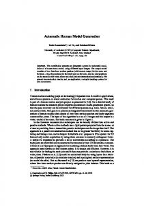
2. Symbolic Simulation Theosim [Als05] is a prototype symbolic simulation tool developed in our research team by Al Sammane et al. In a few words, it takes as input a clock synchronized sequential circuit, and computes the state transition functions and output function in a normalized conditional format. This tool performs a static stabilization of combinational circuits between clock edges. This simulator defines the symbolic value of a signal as a function of the previous symbolic value of all signals of its cone of influence. The architecture of Theosim is given in Figure 1.
Figure 1
Input circuits The input circuit is described in the hardware description language VHDL. The principles of what follows would hold for Verilog as well. The supported VHDL (fully described in [Als04]) is compatible with the standard subset for synthesis [VHDL04], including the abstract data types, but it only recognizes the 1999 syntax for sequential processes. Intermediate Format From the source VHDL file, a proprietary compiler extracts the defining expression of signals and variables for one simulation cycle (i.e. before any stabilization). It is implemented in Mathematica, a complete description is given in [Als04]. It is based on the extraction of the syntactic tree of the source VHDL which is turned into the Mathematica list format. Symbolic Simulation The simulator is based on the VHDL simulation algorithm: at each simulation cycle, the active signals are updated, and processes sensitive to a modified signal are resumed. This step is repeated until stabilization of all signals: it is a delta cycle. Since the symbolic expression of signals and variables is simplified and normalized, a signal is stable if its symbolic value and its previous value are identical. This simulation algorithm is used either to do symbolic simulation or numerical simulation. To perform a simulation for one clock cycle, one has to first set the clock edge, execute one clock synchronized simulation cycle, followed by one or more stabilization cycles. The resulting symbolic expressions are the results of the transition function for each state and output variable of the underlying finite state machine. Modeling The transition functions given by Theosim express the symbolic value of a signal s at a given cycle in terms of its symbolic value at the previous cycle, and symbolic values of the other signals at the current or previous cycle. Two symbols are used for each signal s: the symbolic value at the current cycle is denoted S (capitalized letters of the signal name), the symbolic value at the previous cycle is denoted S$. Example The VHDL text on Figure 2 is an excerpt from a primitive monitor RTL description that will be discussed in Section 4. valid