Artificial Intelligence in Engineering 14 (2000) 15–30 www.elsevier.com/locate/aieng
Automatic generation of control sequences for manufacturing systems based on partial order planning techniques L. Castillo*, J. Fdez-Olivares, A. Gonza´lez Departamento de Ciencias de la Computacio´n e Inteligencia Artificial, E.T.S. Ingenierı´a Informa´tica, Universidad de Granada, 18071 Granada, Spain Received 20 April 1998; received in revised form 25 July 1999; accepted 5 August 1999
Abstract This work presents an approach for the application of artificial intelligence planning techniques to the automatic generation of control sequences for manufacturing systems. These systems have some special features that must be considered in the planning process, but there are difficulties when the usual models of action are used to deal with these features. In this work, a specialized interval-based model of action is defined by extending the classic model of strips giving it more expressiveness so that it is able to deal with these features. In consequence, a specialized planning algorithm for this model of action, called machine, is defined based on a general partial order planning scheme, and it is able to obtain control sequences for manufacturing systems. These control sequences are actually the control program skeleton and may be easily translated into real control programs expressed as GRAFCET charts. q 2000 Elsevier Science Ltd. All rights reserved. Keywords: Partial order AI planning; Model of action; Manufacturing systems; Sequential control program
1. Introduction One of the most appealing aspects of artificial intelligence planning techniques [1–4] is the strong similarity both between the process of planning and the one of programming and between the concept of plan and the one of algorithm. Although there was significant interest and work carried out in the beginning under the general topic of automated program synthesis [5–7] very little advance seems to have been produced since then. Perhaps the problem of the automatic building of programs is too difficult to be faced from a general viewpoint and research should have been focused on more specific domains. In this sense, the domain of manufacturing systems is becoming an area of growing interest for researchers from the field of artificial intelligence planning systems providing a more constrained domain of study. The design of the sequential control program for a manufacturing system is a difficult task which is traditionally carried out by engineers, but artificial intelligence planning techniques are proving to be very useful [8,9], allowing for an errorfree, fast and low-cost building process of these control programs. Furthermore, a new area of study called process
* Corresponding author. Tel.: 134-958-24-4019; fax: 134-958-24-3317. E-mail addresses:
[email protected] (L. Castillo), faro@decsai. ugr.es (J. Fdez-Olivares),
[email protected] (A. Gonza´lez).
planning [10–12] has emerged from the application of planning techniques to machining procedures. The advantages of such systems are clear. First of all, whenever the knowledge used by these systems is guaranteed to be correct, the use of planning techniques would also guarantee that final plans are also correct and free of mistakes or harmful interactions. Secondly, the time taken to obtain plans would always be lower than the time taken to obtain the control program by hand, so these systems would achieve a considerable saving of engineering time. And in third place, if, for some reason, the manufacturing system changes, then, instead of modifying the control program by hand, increasing the probability of introducing mistakes, the control program would be completely rewritten taken into account the new changes in a completely new control program. However, the results obtained are not as realistic as one could expect because either the plan obtained does not have the necessary level of detail, that is, there are actions which are essential for the execution of the control program and they are missing, or the plan is only focused in a small part of the overall manufacturing system. The goal of this work is twofold, on the one hand, the design of a planning system which obtains plans at a sufficiently low level of detail so that it can be considered as a control program which will be called a control sequence. A control sequence is an intermediate representation mechanism used by the planning system, but it contains the
0954-1810/00/$ - see front matter q 2000 Elsevier Science Ltd. All rights reserved. PII: S0954-181 0(99)00025-4
16
L. Castillo et al. / Artificial Intelligence in Engineering 14 (2000) 15–30
Fig. 1. A simple manufacturing system.
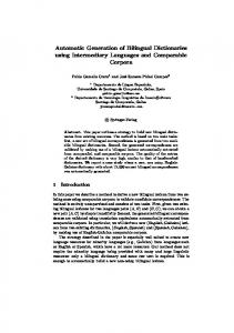
necessary knowledge such that it can be easily translated into a sequential control program expressed as a GRAFCET chart [13] or a lower representation as a Petri net [14]. On the other hand, to extend these plans to the whole of a manufacturing system, including both transport and transformation operations, in order to obtain more realistic and complete plans, closer to what an engineer would call the control program for a manufacturing system. It is known that classic planning systems lack the necessary expressivity to solve real world problems and that this subject has been widely studied [15–18]. However, there are some features of manufacturing systems, which are difficult to deal with even when using these models of action. Therefore, a specialized model of action, which is explained in detail in Ref. [19] and, in consequence, a specialized planning scheme, will be presented which takes these features into account in order to obtain more realistic results. This work is structured as follows. In Section 2, these special features and their motivation are presented. The next sections are devoted to explaining how both the basic model of action of strips [20] and a general partial order planning scheme [21] may be extended in order to deal with these features, configuring a specialized planning scheme called machine. The last sections show some experimental results and how some other interesting features should be included in this planning scheme. 2. Description of manufacturing systems A manufacturing system is the set of processes, machines and factories where raw products are transformed into higher value manufactured products. Fig. 1 shows a toy manufacturing system, which will be used to introduce the problem. It is composed of two tanks, a heater, a mixer, two valves and a pump. These transformations are carried out by the devices of the manufacturing system. The devices in Fig. 1 are the heater, the mixer, the valves and the pump. The operation
Fig. 2. The automata which describes the operation of Valve2.
of every device is defined by a finite state automata where the states of the automata represent all the conditions in which the device is intended to be, and every transition from one state to another represents an action of the device. For example, the automata, which describe the operation of Valve2 in Fig. 1, would be the one shown in Fig. 2. Hence, every action of every device implies both a transformation in the manufacturing system and a change of state in the device. There are many representations for a control program for a manufacturing system like, for example, GRAFCET, Ladder or Petri nets [13,14], but for our purposes, the necessary level of detail to describe a control program is a control sequence. A control sequence is an ordered sequence of actions, i.e. a precedence graph, with all of the actions of devices needed to transform raw products into manufactured ones. The knowledge embedded in a control sequence is sufficient to reason about the behavior of a control program, therefore, aforementioned representations may be considered as lower level representations or extensions of a control sequence. 1 For example, a possible control sequence to heat and carry the water from Tank1 to Tank2 could be like the one shown in Fig. 3. Apparently, a sequence of actions like this could have been generated by any of the state of the art planners, however it has some interesting features that makes it difficult to obtain mainly due to some inherent features of manufacturing domains which must be taken into account. Let us see these features. 2.1. Actions as intervals Every action of every device executes as usual, but it is somehow active, that is, it will maintain its effects, until the next change of state in the automata of the device. For example, let us consider the action TurnOn-Mixer. It is executed in the sequence and the water will become agitated, but it will be active until the execution of TurnOff-Mixer. Therefore, it seems reasonable to consider actions as intervals instead of as isolated points in the sequence, as in classical planners. This is the interval in which the action maintains its effects and it is considered to be active. Some of these effects will disappear after this interval and others will remain. We will call this interval its interval of execution. For example, the interval of execution for the action TurnOn-Mixer would be [TurnOn– Mixer, TurnOff–Mixer]. There are many approaches in the literature that consider actions as intervals, for example, Refs. [15,18,22,23]. In some of them, the end of this interval is defined by the achievement of all of its effects and in the others the end of the interval has an implicit relation with the action itself (for example, a known duration). However, none of these
L. Castillo et al. / Artificial Intelligence in Engineering 14 (2000) 15–30
17
Fig. 3. A small control sequence.
conceptions adequately fit in this problem. For example, let us consider the action of opening Valve1. It achieves its effects at some point before the starting of Pump and it continues active until the shutting of Valve1, later in the sequence, that is its interval of execution is [Open– Valve1, Shut–Valve1]. This shows that the interval of an action is neither defined by the achievement of its effects (it is later) nor has a fixed relation with it, but that it is active while there is no change of state in the device, that is, until the execution of another action that produces a change of state. If such an action does not exist, then the action will continue active until the end of the sequence. This is an important feature of the devices in a manufacturing system. One can plan the execution of an action and the action will execute, but it will continue active, and its effects maintained, if no change of state is produced. If the end of the interval of execution of an action depends on the execution of another action then, it depends on the process of planning itself, that is, the end of the interval will have also to be planned. 2.2. Requirements during the actions The second one, and very much related to the former, is that, if actions are to be considered as intervals instead of as points, then the requirements which must hold in order to guarantee a correct execution of an action should also take into account this interval. That is, in addition to classical preconditions, as conditions which must hold before the action, it is necessary to define some kind of simultaneous requirements as conditions which must hold during the interval of execution of the action. These requirements are a form of the during relation in Ref. [15]. For example, let us consider the action TurnOn-Pump. It requires the valves to be open before the pumping starts, but it is also necessary for them to remain open until the end of pumping, that is, during the interval of execution defined as [TurnOn– Pump, TurnOff–Pump]. This kind of requirement is also present in the literature. Simultaneous requirements also appear in Ref. [18] and later in an application by Klein et al. [24], but the difference here is that the interval which defines the protection for these simultaneous requirements does not end with the achievement of the effects of the action, but rather while the action is active, that is until
the next change of state produced by the execution of another action. If actions are not considered as explained above, it is difficult to guarantee that valves should be open during the interval of execution of the pump, that is, in the interval [TurnOn-Pump, TurnOff-Pump], or that the water should be in agitation during the heating of the water or that Valve1 should be closed during the agitation of the water. 2.3. Safe states Finally, if one thinks about the example from a causal viewpoint, then a strictly correct sequence would have also been the one shown in Fig. 4 because there is nothing that tells the devices to be off once the water is hot and it is in Tank2. However, the truth is that there are safe states in the automata which describe the operation of devices and that these states must be reached by every device before the end of the sequence. Actions needed to reach these safe states are essential for the execution of the control sequence and they are missing in the sequence in Fig. 4, so the correct sequence is actually the one shown in Fig. 3. One way to introduce this feature in the process for the building of sequences could just be by including these safe states in the goal of the problem. Although this achieves a safe state for every device it seems too global, that is, it may be difficult to decide the point in the sequence in which the device reaches a safe state, or even if it would be necessary to use the same device later in the sequence and return it to a safe state. It seems that this decision is specific to each action that does not leave it in a safe state. Therefore, the need to leave the device in a safe state can be modeled as a later requirement of some actions, that is, as a condition that must hold after the action. In the example of the valve, the safe state is the one in which the valve remains shut, so the need to shut it as soon as possible could be modeled like a later requirement of the action which opens the valve. In summary, these are the basic features which must be taken into account in order to reason about the actions that take place in a manufacturing system, and in consequence, to obtain sequences like the one shown in Fig. 3. Basically, actions are considered as intervals in which they maintain
Fig. 4. An alternative control sequence.
18
L. Castillo et al. / Artificial Intelligence in Engineering 14 (2000) 15–30
their effects. As seen before, considering actions as intervals instead of as points is not a new feature. However, the end of these intervals comes from the execution of another action and, in consequence, it depends on the process of planning itself, or in other words, the end of the intervals of the actions must also be planned. In addition to this, new types of requirements are needed in order to both adequately guarantee this interval and to leave devices in a safe state before the end of a sequence. These are very distinguishing features which do not fit adequately either into known models of action which consider actions as a point in a sequence, or in others which consider actions as intervals, making the sequence in Fig. 3 very difficult to obtain. Therefore, the following model for actions and plans has been defined.
3. A model for actions and plans The model of action needed to deal with the previous features may be obtained by extending the basic model of strips [20] in order to give devices a higher importance and to allow for the new types of requirements. A more detailed description of this model of action may be found in Ref. [19]. Every device in a manufacturing system is represented as an agent whose operation is described by a finite state automata. Thus, every agent has a set of states E, which describe all the possible conditions in which it is intended to be, and a set of actions A, each of which describes a transformation as well as a change of state in the agent. Additionally, an agent has a name N, which must be unique, a set of variables V, which are used to represent the objects related to the operation of the agent (like for instance products, chemicals, interconnection points between agents or constants) and a set of codesignation constraints C defined on the set of variables, which define the set of valid values for every variable. Agent kN; E; V; C; Al Every action of every agent is defined by a unique name N, a set of effects, which is represented by means of an addition list ADD, and a deletion list DEL of literals that represent the transformation made by the action, and a set of requirements, divided into a list of previous requirements ANT, that must hold before the action, a list of simultaneous requirements DUR which must hold during the interval of execution of the action and a list of later requirements POST, that must hold after the action. Action kN; ADD; DEL; ANT; DUR; POSTl
Example 1. This example roughly shows how Valve2 seen previously could be described by this model (using a Lisp-based notation).
(AGENT (N Valve2) (E OPEN SHUT) (V ?SOURCE ?IN ?OUT ?CHEM) (C (?SOURCE NIL) (?IN (PUMP)) (?OUT (TANK2)) (?CHEM NIL)) (A (ACTION (N Open-Valve2) (ADD (STATE Valve2 OPEN) (OPENFLOW ?CHEM ?SOURCE ?OUT)) (DEL (STATE Valve2 SHUT)) (ANT (STATE Valve2 SHUT)(OPENFLOW ?CHEM ?SOURCE ?IN)(CONTAINS ?CHEM ?SOURCE)) (DUR (OPEN-FLOW ?CHEM ?SOURCE ?IN)) (POST (STATE Valve2 SHUT))) (ACTION (N Shut-Valve2) …)) )
As may be seen, the interval of execution of an action of an agent does not need to be included in its definition because it does not depend on the action itself but on the decision to include another action of the same agent that changes the state reached by the former action. Actually, the interval of execution of an action is defined during the building process of the sequence. The description of the problems that appear in a manufacturing system consists of a set of transformations, which must be made on raw products in order to obtain the manufactured ones. Although most of the manufacturing processes are quite complex, in this paper only simple transformations are considered; however, they are expressive enough to show the main difficulties during the building process of a control sequence. Thus, a problem P kD; I; Gl is defined by the following components. Domain. A domain D is a knowledge-based model of the manufacturing system and it is divided into a set of agents, which represents the set of devices, their operation and their interconnections described by this model of action, and a set of axioms, which describe facts which are always true. Initial. The initial state I is a conjunction of literals, which describe the initial state of both the manufacturing system and the raw products. Goal. A goal G is a conjunction of literals, which describe the transformation, needed to obtain manufactured products from raw ones. 3.1. Plans The solution to these problems consists in an ordered
L. Castillo et al. / Artificial Intelligence in Engineering 14 (2000) 15–30
Fig. 5. An alternative manufacturing system.
sequence of actions of the agents of the domain, which achieves the goal starting from the specified initial state. This can be called a control sequence or an operation procedure [25], but in this paper, it will also be called a plan. Example 2. Let us consider the manufacturing system shown in Fig. 5. The set of agents and their actions are shown in Table 1. For example, the agent called PUMP2 is a pump, and it may be either connected with the action ONPUMP2 or disconnected with the action OFFPUMP2. The set of actions of the valves has been abbreviated. Let us suppose that the initial state shows the valves closed, and the pumps off. Then, Fig. 6 shows a plan to carry the water to TANK3, where START and END are two dummy actions defined with the same meaning as in SNLP [26] or UCPOP [21]. This is only a structural description of what we consider a plan, the following explains in detail the semantics behind this conception of plan. 3.2. The semantics of plans Actions have an interval of execution, but this interval is defined between every two consecutive actions in the plan of the same agent, thus it may change during the building process of the plan as actions are included in the plan. Let us consider the plan shown in Fig. 7 as an intermediate step during the building process of the overall plan for Example 2. One may see that the action Open.Valve2 will execute before Open.V23, but it will continue active Table 1 The set of agents in Fig. 5 Type of device Agents
Actions
Pumps
ONPUMP1, OFFPUMP1 ONPUMP2, OFFPUMP2 Open.Valve1, Shut.Valve1, Open.V13, etc.
Valves
PUMP1 PUMP2 Valve1, V13, V14 Valve2, V23, V24
19
until the end of the plan. Thus, its interval of execution is [Open.Valve2, END]. Now let us consider that the action Shut.Valve2 is included in the plan obtaining the plan as shown in Fig. 8. This action produces a change of state in Valve2 that affect the state reached by Open.Valve2, so the interval of execution for Open.Valve2 is revised and redefined as [Open.Valve2, Shut.Valve2]. At once, the interval of execution of Shut.Valve2 appears as [Shut.Valve2, END]. Although actions have an interval of execution, this interval is not previously defined by the action itself but it depends on the building process of a plan. This feature will be very important during the building process of the plan. Concurrent execution of several actions is something natural in manufacturing systems and it is straightforwardly modeled in the plan. Actions whose intervals of execution overlap are concurrently executing. Let us consider the sequence in Fig. 6: the intervals of execution of Open.Valve2, Open.V23 and OnPump2 overlap. This means that there is a moment (just before OffPump2) in which the three actions are executing concurrently, that is, the three actions are simultaneously active. Although the examples seen so far show a total order of actions, plans can have a partial order structure. A partial order is used not only as a least commitment strategy to represent a class of total order plans, but also to represent possible concurrency. For example, let us consider again the manufacturing system shown in Fig. 5. A plan to carry ACID from TANK1 to TANK4 and WATER from TANK2 to TANK3 could be the one shown in Fig. 9. The fact that both branches of the program are unordered means that there is no commitment between them and, therefore, the intervals of execution of actions in both branches could possibly overlap, that is, they could possibly execute concurrently. An immediate consequence of the possibility of concurrent execution of actions is that if the intervals of two actions can possibly overlap, then both actions should not interfere, that is, they must not have any opposite effect. This will be called an interference. Causal links [21,26] are also considered in the plan. They define intervals of protection for the literals that appear in the requirements lists of an action, which have been previously solved by another action. The actions which these literals belong to are called consumers and the actions which solve them are called producers (in terms of Ref. [21]). Since there are three lists of requirements of different nature, the interval which defines a causal link can differ depending on the type of requirement. The causal link associated with a previous requirement is defined from the producer of the literal until the consumer. When the requirement is a simultaneous one, then the causal link must be defined during the entire execution interval of the action, that is, from the producer until the end of the interval of the
20
L. Castillo et al. / Artificial Intelligence in Engineering 14 (2000) 15–30
Fig. 6. A plan to carry the water to TANK3.
consumer. Since the end of an interval of execution may change during the building process of a plan, causal links related to these requirements may also change. Later requirements have a different nature, they only need to be satisfied and they do not need to be protected throughout the plan like previous or simultaneous ones. Therefore, causal links with respect to later requirements are not considered. An action threatens a causal link if the literal associated with the causal link appears in the deletions list of the action. Since causal links represent intervals of protection for these literals, the interval of execution of an action, which threatens a causal link, and the interval of the causal link must never overlap. Neither interferences nor threats are allowed in a valid plan and they must be avoided by the usual methods of promotion and demotion [21] by adding ordering constraints in order to avoid these harmful overlappings. The only notion of time in a plan like the ones in Figs. 6 and 9 is the relative ordering between its actions, and this is only a qualitative notion like in Ref. [27] or Ref. [18]. The inclusion of a metric notion of time would be, of course, useful, however the main problem that appears in the building process of such a plan is the search for a correct interleaving of the actions and a qualitative notion of time is sufficient, although it is more conservative than a metric time, which would surely provide a more precise interleaving. This must also be taken into account to avoid considering this work as a scheduling approach since, in this paper, a solution to a problem is solely a correctly interleaved plan, not the fastest valid plan. Bearing in mind these conceptions of actions, problems and plans, the following section describes a partial order planning scheme, called machine, designed by adapting a general causal link based partial order algorithm [21] to deal with this model of actions and plans, which is able to obtain the plans seen so far. 4. machine: machine a partial order planner for the building of control sequences machine is a generative refinement planning scheme [21] whose architecture is shown in Fig. 10. It uses four data structures to store the information during the planning process: an Agenda, the Plan and its Links, and the
Fig. 7. An intermediate plan.
Domain in consideration. The Domain is the knowledge-based model of the manufacturing system, that is, the set of agents and their actions built by means of the model of action described in Section 3, and the set of axioms. The Plan is a partially ordered set of nodes, where every node may be an instantiated action from the Domain or a subgoal, together with its Links, that is, the set of the existing causal links, which describes the causal structure of the plan, the plan rationale [28]. In addition, the Agenda which is a set of tasks each of which describes a pending problem in the plan. The algorithm of machine is described in Fig. 11. The start point is a null Plan with two dummy actions, START and END which encode the planning problem P kD; I; Gl the initial state I is encoded as the addition list of the action START, the goal G is encoded as unsatisfied previous requirements of END. The Agenda initially contains only these pending subgoals specified in the goal G and Links is initially empty. Over this initial plan, a refinement process is applied which, at every step, solves a pending problem in Agenda until there are no more pending problems or a problem cannot be solved. The different pending problems which may be found in Agenda are: (a) pending subgoals motivated by requirements of actions which have not been satisfied yet; (b) threats from actions to causal links; (c) interferences between actions and (d) an order inconsistency motivated by a loop in the order structure, which must be a strict order. The search process to solve the tasks in the Agenda is a basic depth first engine over the set of choices to solve every task. 4.1. Description of modules The three basic submodules of machine are shown in boldface. Although they basically play the same role as the ones of POP [21], a considerable effort has to be done to adapt them to work on the model of action and plans described in Section 3, thus only the most important differences will be described. SelectTask. This module selects the first task in Agenda
Fig. 8. The intermediate plan after Shut.Valve2.
L. Castillo et al. / Artificial Intelligence in Engineering 14 (2000) 15–30
21
Fig. 9. A plan to carry ACID from TANK1 to TANK4 and WATER from TANK2 to TANK3.
in order to solve it. Tasks in Agenda are ordered using the following scheme: first, order inconsistency, then interferences, threats and subgoals. Order inconsistency is the first one because it has no solution and it always leads to backtracking. Subgoals are the last ones because they are delayed until all the interferences and threats are solved. In addition to this, subgoals are also ordered amongst them by their relative ordering in such a way that subgoals closest to START are solved before the furthest ones. HowToDoIt? This module analyzes a selected task from the Agenda and it builds a list with all the possible choices to solve it. An inconsistent order has no solution, so the list will be empty. The choices to solve interferences and threats
are the known methods of promotion or demotion, nondeterministically. Subgoals are literals, which may be solved if they unify either with the axioms or with a literal in the addition list of an existing action in the plan or a new action from the Domain. Since this process is based on a most general unifying algorithm, the codesignation constraints defined on the variables of the agents play an important role by rejecting undesirable unifications and thus, making the list of choices smaller and the search process faster. DoIt. This module applies one of the existing choices in the list built by HowToDoIt? to solve a problem, that is, it tries to solve the problem. This is the most important
Fig. 10. The architecture of machine.
22
L. Castillo et al. / Artificial Intelligence in Engineering 14 (2000) 15–30
Fig. 11. The algorithm of machine.
submodule of machine. Let us see how the different problems in Agenda are solved. 1. An order inconsistency has no solution. The order relation between the nodes of Plan must be a strict order. If, for some reason, an order constraint is added and the resulting order relation is not strict, that is, it contains a loop, then the search process will backtrack to look for a different plan. 2. Pending subgoals are solved either by an axiom or by reusing a previously existing action in the plan or by a new action from the domain. If a subgoal is solved by an axiom, then it disappears from Plan, otherwise, the following process is followed. Subgoals related to simultaneous and previous requirements are solved by producers, which must be before the consumer action, and later requirements are solved by producers which must be after the consumer. If an existing action in Plan is reused, then it is adequately ordered in relation to the consumer and a causal link is added to Links to protect it. The inclusion of a new action in Plan to solve a pending subgoal implies the following tasks. 3. First, it is adequately ordered with respect to the consumer, all of its requirements are added as pending subgoals in Agenda and the new causal link is added to Links. 4. Secondly, when a new action is included in Plan, the end of its interval of execution is unknown, so, by default, it is assumed that its end is the dummy action END. However, the true end of all of the actions in the plan is continuously searched as shown in the intermediate plans in Figs. 7 and 8. Since the end of the interval of an action implies a change of state in the agent which carries out the action, every time an action solves a subgoal of change of state for its own agent then the end of the interval of this action has been found, and it is updated in Plan and in the causal links of Links related to this interval. 5. Thirdly, if new interferences or threats have appeared, then they are added to Agenda also as pending tasks. 6. Interferences and threats are found when there is harmful overlapping between the intervals of execution of actions and the intervals defined by a causal link as explained in Section 3. Promotions and demotions to solve
interferences and threats are not applied between actions but between their intervals of execution. When an action is promoted (or demoted) over another action, it is promoted over all its interval of execution, not only the action.
Example 3. Let us consider the intermediate plan shown in Fig. 8. If the action Shut.Valve2 interferes with the action OnPump2, then its promotion will be over the interval of execution of OnPump2 defined by [OnPump2, OffPump2], that is, Shut.Valve2 will be ordered after OffPump2.
However, machine can delay the solution of some threats and interferences for a later moment in the resolution process. The reason is that, as mentioned before, not all of the intervals of the actions in Plan are known, some of them are known and some of them will be known as pending subgoals are solved. Therefore, if a threat or an interference is related to an undefined interval then it should be delayed until the end of the involved intervals are known. In order to do that, these kinds of threats and interferences are ordered in Agenda after pending subgoals giving them less priority. Later, if the solution of some of these subgoals finds the end of some of these problematic intervals, Plan and Links will be updated and the threat or interference will be back at the beginning of Agenda and, so, solved appropriately.
Example 4. Let us consider again the intermediate plan shown in Fig. 8. One of the simultaneous requirements of the action OnPump2 could be (STATE VALVE2 OPEN), i.e. that Valve2 must be open during its interval of execution [OnPump2, OffPump2]. This requirement would have been satisfied by the action Open.Valve2 so there would be a causal link to protect the literal (STATE VALVE2 OPEN) in the interval I1 Open:Valve2; OffPump2. The action Shut.Valve2, whose interval of execution is I2 Shut:Valve2; END, violates this requirement and, even more, its interval of execution I2 could possibly
L. Castillo et al. / Artificial Intelligence in Engineering 14 (2000) 15–30 Table 2 Some experimental results Plan
Generated nodes
Explored nodes
Time (s)
Size of plan
Fig. 3 Fig. 6 Fig. 9 Fig. 13
56 38 69 217
39 30 51 144
11 5 16 374
12 8 14 40
overlap with the interval of protection I1 of the causal link producing a possible threat which must be solved by reordering I1 and I2 by promotion or demotion. However, the fact that the end of I2 is the action END means that, until now, the end of I2 is unknown and demotion is not possible yet, therefore this threat should be delayed until it is known, in order to guarantee a correct choice between promotion or demotion. If Valve2 were used again in the plan, the end of this interval will become known and the threat solved. However actually, this interval I2 will be the same even when all the subgoals have been solved. Only then, when there are no more pending tasks in Agenda, this threat will be solved by promoting I2 after I1, because demoting I2 before I1 will produce an order inconsistency.
This is also a least commitment heuristic which could more or less say the following: “I don’t try to solve a problem if it is not sharply defined”. When there are no pending problems in Agenda, machine ends with success, thus it guarantees that all of the subgoals have been solved and that the final plan, i.e. the
23
control sequence, is free of any possible harmful interaction between its actions like for example interferences or threats. The examples seen so far are very simple, they have only been used to introduce the problem and they would have also been generated correctly by hand. That is, all of the subgoals would have been solved and the final control sequence would be free of any possible harmful interaction between its actions like for example interferences or threats. However, in real size complex manufacturing systems, like the one shown in Section 5, where there could be many devices executing concurrently, the generation of a control sequence which achieves the goal and that is free of interferences and threats becomes an important problem. When there are no pending problems in Agenda, machine ends with success and it guarantees that all of the subgoals have been solved and that the final control sequence has neither interferences nor threats. 5. Experimental results machine has been implemented in COMMON LISP and has been tested using the problems shown throughout this paper. It found the correct plan, i.e. control sequence, for all of them and its behavior is shown in Table 2. As it has been seen in Section 2, manufacturing systems and the desired final plan have some very distinguishing features which make known planning systems very difficult to apply. Due to this difficulty, this section does not show how other wellknown planners could have behaved on these problems, even if they were able to solve them at the desired level of detail. We hope the problems presented in this work are expressive enough to overcome this problem.
Fig. 12. A real world manufacturing system.
24
L. Castillo et al. / Artificial Intelligence in Engineering 14 (2000) 15–30
Table 3 The set of agents in the manufacturing system shown in Fig. 12 Type of device
Agents
Pumps Valves
MP, EP, B1, AP, BP MV, MV2, EV, V1, V2, SV, ST1, ST2, AV, AS1, AS2, VB2 Mix1, Mix2 Heat1, Heat2 Belt-1, Belt-2 Bottler
Mixers Steam heaters Conveyor belts Bottler
This table also includes the results of a real-size manufacturing problem, which is described in detail below. The final result of machine is a control sequence, it is not exactly a control program but it has the necessary level of detail to be considered as such. Furthermore, in Refs. [29,30] we show in detail how these control sequences may be translated into Petri nets [14] and GRAFCET charts [13], as true representations for a control program, and very useful tools in the design and modeling of manufacturing systems. The GRAFCET charts translated from the problems shown in Table 2 appear in Appendix A. 5.1. A real size problem The manufacturing system is shown in Fig. 12 and the list of agents is shown in Table 3. The problem consists in adding an ingredient (initially contained in ADDITIVE-1) to the milk initially contained in MILK-TANK and then proceed to bottle the mixture. The planning problem P kD; I; Gl is defined as follows. • D. The knowledge based model of this manufacturing system has four axioms, 24 agents (valves, pumps, mixers, steam heaters, conveyor belts and a bottler) and 48 different actions, a small part of which are the following. (AXIOMS (OPEN-FLOW ?CHEM ?X ?X) (CONTAINS STEAM BOILER) (CONTAINS BOTTLES BOTTLES-STORAGE) (OPEN-FLOW BOTTLES BOTTLES-STORAGE BELT2) ) (AGENT (N SV) (E ON OFF) (V ?SRC ?IN ?OUT ?CHEM) (C (?SRC (BOILER)) (?IN (BOILER)) (?OUT (P2)) (?CHEM NIL)) (A (ACTION (N OPEN-SV) (AD (STATE SV ON) (OPEN-FLOW ?CHEM ?SRC ?OUT) (OPENING-FLOW ?CHEM ?SRC ?OUT SV) ) (SUP (STATE SV OFF)) (ANT (CONTAINS ?CHEM ?SRC) (OPEN-
FLOW ?CHEM ?SRC ?IN) (STATE SV OFF)) (DUR (OPEN-FLOW ?CHEM ?SRC ?IN)) (POST (STATE SV OFF)) ) (ACTION (N SHUT-SV) (AD (STATE SV OFF)) (SUP (STATE SV ON) (OPENING-FLOW ?CHEM ?SRC ?OUT SV) (OPEN-FLOW ?CHEM ?SRC ?OUT) ) (ANT (OPENING-FLOW ?CHEM ?SRC ?OUT SV) (STATE SV ON)) (DUR) (POST) ))) (AGENT (N ST1) (E ON OFF) (V ?SRC ?IN ?OUT ?CHEM) (C (?SRC (BOILER)) (?IN (P2)) (?OUT (HEAT1)) (?CHEM NIL)) (A (ACTION (N OPEN-ST1) (AD (STATE ST1 ON) (OPEN-FLOW ?CHEM ?SRC ?OUT) (OPENING-FLOW ?CHEM ?SRC ?OUT ST1) ) (SUP (STATE ST1 OFF)) (ANT (CONTAINS ?CHEM ?SRC) (OPENFLOW ?CHEM ?SRC ?IN) (STATE ST1 OFF)) (DUR (OPEN-FLOW ?CHEM ?SRC ?IN)) (POST (STATE ST1 OFF)) ) (ACTION (N SHUT-ST1) (AD (STATE ST1 OFF)) (SUP (STATE ST1 ON) (OPENING-FLOW ?CHEM ?SRC ?OUT ST1) (OPEN-FLOW ?CHEM ?SRC ?OUT) ) (ANT (OPENING-FLOW ?CHEM ?SRC ?OUT ST1) (STATE ST1 ON)) (DUR) (POST) ))) (AGENT (N AP) (E ON OFF) (V ?SRC ?DST ?ADDITIVE ?BASE) (C (?SRC (RTANK)) (?DST (TANK2)) (?ADDITIVE NIL) (?BASE NIL)) (A (ACTION (N AP-ON) (AD (STATE AP ON) (ADDED ?BASE ?ADDITIVE) (FLOW ?ADDITIVE ?SRC ?DST) (FLOWING ?ADDITIVE ?SRC ?DST AP) ) (SUP (STATE AP OFF) (CONTAINS ?ADDITIVE ?SRC))
L. Castillo et al. / Artificial Intelligence in Engineering 14 (2000) 15–30
Fig. 13. The control sequence.
25
26
L. Castillo et al. / Artificial Intelligence in Engineering 14 (2000) 15–30
(ANT (TEMP ?BASE HIGH) (CONTAINS ?BASE ?DST) (CONTAINS ?ADDITIVE ?SRC) (OPEN-FLOW ?ADDITIVE ?SRC ?DST) (STATE AP OFF) ) (DUR (TEMP ?BASE HIGH) (CONTAINS ?BASE ?DST) (MIX ?BASE ?DST) (OPEN-FLOW ?ADDITIVE ?SRC ?DST) ) (POST (STATE AP OFF)) ) (ACTION (N AP-OFF) (AD (STATE AP OFF)) (SUP (STATE AP ON) (FLOWING ?ADDITIVE ?SRC ?DST AP) (FLOW ?ADDITIVE ?SRC ?DST) ) (ANT (FLOWING ?ADDITIVE ?SRC ?DST AP) (STATE AP ON)) (DUR) (POST) ))) (AGENT (N BELT1) (E ON OFF) (V ?SRC ?DST ?SOLID) (C (?SRC (ADDITIVE1 ADDITIVE2)) (?DST (RTANK)) (?SOLID NIL)) (A (ACTION (N BELT1-ON) (AD (STATE BELT1 ON) (CONTAINS ?SOLID ?DST) (FLOW ?SOLID ?SRC ?DST) (FLOWING ?SOLID ?SRC ?DST BELT1) ) (SUP (STATE BELT1 OFF) (CONTAINS ?SOLID ?SRC)) (ANT (CONTAINS ?SOLID ?SRC) (OPEN-FLOW ?SOLID ?SRC BELT1) (STATE BELT1 OFF) ) (DUR (OPEN-FLOW ?SOLID ?SRC BELT1)) (POST (STATE BELT1 OFF)) ) (ACTION (N BELT1-OFF) (AD (STATE BELT1 OFF)) (SUP (STATE BELT1 ON) (FLOWING ?SOLID ?SRC ?DST BELT1) (FLOW ?SOLID ?SRC ?DST) ) (ANT (FLOWING ?SOLID ?SRC ?DST BELT1) (STATE BELT1 ON)) (DUR) (POST) ))) • I. All the agents in the system are off, there is milk in MILK-TANK, there is steam in the Boiler and the ingredient is in ADDITIVE-1.
Fig. 14. GRAFCET charts for the sequences in (a) Fig. 3, (b) Fig. 6 and (c) Fig. 9.
• G. The goal is only expressed as (added ingredient milk)(bottled milk) although it involves many intermediate actions such as moving the milk and the ingredient, heating it, mixing the ingredient, proceeding to feed the bottler with both bottles and mixture. All these intermediate actions are motivated by the different requirements of other actions, all of them trying to solve the goal. The control sequence obtained by machine is shown in Fig. 13 where the upper line of the sequence shows the main body of the sequence and how, as the different stages of the sequences are completed, the different agents are turned off in parallel without interfering with the development of the main sequence. It can be seen that the mixture process will take place in TANK2. The main sequence shows how the milk is pumped into Tank1 and, at once, the ingredient is carried into RTANK. Then, the milk is heated in TANK1 (if we suppose that there is not any drop in temperature, this decision is completely correct), pumped into TANK2, the ingredient is added and mixed and, finally, BOTTLER and BELT-2 complete the process.
L. Castillo et al. / Artificial Intelligence in Engineering 14 (2000) 15–30
Fig. 15. The GRAFCET chart for the sequence in Fig. 13.
27
28
L. Castillo et al. / Artificial Intelligence in Engineering 14 (2000) 15–30
Table 4 Logic formulae of triggering conditions for the GRAFCET in Fig. 15 CT1
CT2 CT3
CT4 CT5 CT6 CT7 CT8
CT9 CT10 CT11 CT12 CT13 CT14 CT15 CT16
CT17 CT18 CT19 CT20
CT21 CT22 CT23 CT24 CT25 CT26 CT27 CT28
CT29
CT30 CT31
(STATE MP OFF) ∧ (STATE MV OFF) ∧ (STATE MV2 OFF) ∧ (STATE EP OFF) ∧ (STATE EV OFF) ∧ (STATE MIX1 OFF) ∧ (STATE HEAT1 OFF) ∧ (STATE SV OFF) ∧ (STATE ST1 OFF) ∧ (STATE ST2 OFF) ∧ (STATE V1 OFF) ∧ (STATE B1 OFF) ∧ (STATE V2 OFF) ∧ (STATE HEAT2 OFF) ∧ (STATE MIX2 OFF) ∧ (STATE AV OFF) ∧ (STATE AP OFF) ∧ (STATE AS1 OFF) ∧ (STATE AS2 OFF) ∧ (STATE BELT1 OFF) ∧ (STATE VB2 OFF) ∧ (STATE BP OFF) ∧ (STATE BOTTLER OFF) ∧ (STATE BELT2 OFF) ∧ (CONTAINS MILK MILKTANK) ∧ (TEMP MILK LOW) ∧ (CONTAINS ENZYME ENZYME-TANK) ∧ (CONTAINS FLOUR ADDITIVE1) ∧ (CONTAINS COCA_ADDITIVE1) (STATE BOTTLER ON) ∧ (BOTTED MILK) (STATE AP ON) ∧ (ADDED MILK COCOA) ∧ (FLOW COCOA RTANK TANK2) ∧ (FLOWING COCOA RTANK TANK2 AP) (STATE AP OFF) (STATE BOTTLER OFF) (STATE AV ON) ∧ (OPEN-FLOW COCOA RTANK TANK2) ∧ (OPENING-FLOW COCOA RTANK TANK2 AV) (STATE MIX2 ON) ∧ (MIX MILK TANK2) ∧ (MIXING MILK MIX2) (STATE B1 ON) ∧ (CONTAINS MILK TANK2) ∧ (FLOW MILK TANK1 TANK2) ∧ (FLOWING MILK TANK1 TANK2 B1) (STATE HEAT1 ON) ∧ (TEMP MILK HIGH) (STATE HEAT1 OFF) (STATE B1 OFF) (STATE MIX2 OFF) (STATE AV OFF) (STATE ST1 ON) ∧ (OPEN-FLOW STEAM BOILER HEAT1) ∧ (OPENING-FLOW STEAM BOILER HEAT1 ST1) (STATE MIX1 ON) ∧ (MIX MILK TANK1) (MIXING MILK MIX1) (STATE MP ON) ∧ (CONTAINS MILK TANK1) ∧ (FLOW MILK MILK-TANK1) ∧ (FLOWING MILK MILK-TANK TANK1 MP) (STATE MP OFF) (STATE MIX1 OFF) (STATES ST1 OFF) (STATE MV2 ON) ∧ (OPEN-FLOW MILK MILK-TANK TANK1) ∧ (OPENING-FLOW MILK MILK-TANK TANK1 MV2) (STATE MV2 OFF) (STATE V2 ON) ∧ (OPEN-FLOW MILK TANK1 TANK2) ∧ (OPENING-FLOW MILK TANK1 TANK2 V2) (STATE V2 OFF) (STATE MV ON) ∧ (OPEN-FLOW MILK-TANK P1) ∧ (OPENING-FLOW MILK MILK-TANK P1 MV) (STATE MV OFF) (STATE SV ON) ∧ (OPEN-FLOW STEAM BOILER P2) ∧ (OPENING-FLOW STEAM BOILER P2 SV) (STATE SV OFF) (STATE BELT2 ON) ∧ (CONTAINS BOTTLES BOTTLER) ∧ (FLOW BOTTLES-STORAGE BOTTLER) ∧ (FLOWING BOTTLES BOTTLES-STORAGE BOTTLER BELT2) (STATE BELT1 ON) ∧ (CONTAINS COCOA RTANK) ∧ (FLOW COCOA ADDITIVE1 RTANK) ∧ (FLOWING COCOA ADDITIVE1 RTANK BELT1) (STATE V1 ON) ∧ (OPEN-FLOW MILK TANK1 B1) ∧ (OPENING-FLOW MILK TANK1 B1 V1) (STATE V1 OFF)
Table 4 (continued) CT32 (STATE BELT1 OFF) CT33 (STATE BP ON) ∧ (CONTAINS MILK BOTTLER) ∧ (FLOW MILK TANK2 BOTTLER) ∧ (FLOWING MILK TANK@ BOTTLER BP) CT34 (STATE BP OFF) CT35 (STATE AS1 ON) ∧ (OPEN-FLOW COCOA ADDITIVE1 BELT1) ∧ (OPENING-FLOW COCOA ADDITIVE1 BELT1 AS1) CT36 (STATE AS1 OFF) CT37 (STATE BELT2 OFF) CT38 (STATE VB2 ON) ∧ (OPEN-FLOW MILK TANK2 BOTTLER) ∧ (OPENING-FLOW MILK TANK2 BOTTLER VB2) CT39 (STATE VB2 OFF) CT40 TRUE CT41 TRUE CT42 TRUE CT43 TRUE CT44 TRUE
6. Conclusions and extensions This work has been motivated by the need to apply artificial intelligence planning techniques to the design of control programs for manufacturing systems, allowing for an error-free, fast and low cost building process for such control programs. This need has shown that the domain of manufacturing systems has some basic properties which must be taken into account in order to ensure correct reasoning about the actions which take place in such a domain, and to ensure a sufficiently low level of detail in the final plan. Since these features do not adequately fit into known models of action, an effort has been made to extend both the basic model of action of strips [20] and a basic partial order planning scheme [21] to deal with these features. The final result is the planning system presented in this paper, called machine, which is able to obtain control sequences for manufacturing systems. Although machine has been tested successfully on several problems it can only be considered as a step forward in the resolution of the problems which appear in manufacturing systems. The reason is that this is a very rich domain with many problems of different natures, which should be taken into account by an autonomous problem solver. However, the core of the problem solver is actually a planning system and all of these problems may be built like folders or extensions over this planning core, configuring an integrated planning system similar to OPlan-2 [31] or SIPE [28]. Some of the important problems, which we hope to deal with in the near future, are the following: • Perhaps the most important problem is the inclusion of a metric time in order to both quantify the intervals of actions and allow for the representation of gradual achievement of effects along this interval. In real problems, these intervals are not perfectly quantified
L. Castillo et al. / Artificial Intelligence in Engineering 14 (2000) 15–30
•
•
•
•
and they may be vague. Time map managers [22,23] seem to be very promising in this task. Manufactured products are really complex and a classic conjunctive goal is not enough to deal with complex goals. It is necessary to define behavioral goals as an ordered set of transformations on raw products, this is known as a recipe. At present, machine does work with goals whose literals have a partial order structure, but this will be dealt with in a forthcoming paper. In these domains, there are what could be called procedures: complex problems which can be decomposed into an ordered sequence of smaller subproblems. The planning system must know these procedures and it must also know how to work with them. This problem points directly to HTN techniques [32]. The control programs seen in this paper are intended to work in an open loop manner, that is, with no feedback from the environment. Real control programs have feedback from sensors in the environment and the planning system must be able to include the information supplied by these sensors in the planning process. This seems to be the most challenging problem because it implies both: (a) The ability of the planning system to adapt its behavior to the different ways in which sensors may appear. Case-based and analogical techniques seem very promising in this task because they also seem to be the techniques used by humans in the same role. (b) The ability to include some kind of conditional behavior in the plan because the information given by sensors is not always available at planning time. And finally, although machine has been tested successfully on the examples seen throughout this work, the search engine may be improved in order to face more complex problems. At present we have developed a best first engine for machine, more in accordance with the state of the art planners, but usual heuristic functions to guide the search [33,34] seem to give very little information and the search process is too slow. However, this will also be dealt in a forthcoming work.
Acknowledgements This work has been supported by the CICYT under project TIC95-0453.
29
the sequence, which may be used as triggering conditions. 2 Although the translation process and some interesting properties are explained in detail in Ref. [29], Figs. 14 and 15 illustrate the final translations to GRAFCET charts of the control sequences in Table 2. These charts are actually a valid representation for a control program for a manufacturing system and they may be implemented in most known control systems. It may be seen that the main difference with respect to the control sequences is the inclusion of synchronization stages in the GRAFCET (the stages named as WAIT).
References [1] Allen JF, Hendler J, Tate A. Readings in planning. Los Altos, CA: Morgan-Kaufmann, 1990. [2] McDermott D. Regression planning. Int J Intell Syst 1991;6:357–416. [3] McDermott D, Hendler J. Planning: what is, what it could be, an introduction to the special issue on planning and scheduling. Artificial Intell 1995;76:1–16. [4] Nilsson NJ. Principles of artificial intelligence. Tioga Publishing, 1980. [5] Green C. Application of theorem proving to solving. IJCAI 1969;741–7. [6] Manna Z, Waldinger RJ. Knowledge and reasoning in program synthesis. Artificial Intell 1975;6:175–208. [7] Waldinger RJ. Constructing programs automatically using theorem proving. PhD thesis, Carnegie-Mellon University, 1969. [8] Aylett R, Petley G, Chung P, Soutter J, Rushton A. Planning and chemical plan operation procedure synthesis: a case study. In: Fourth European Conference on Planning, 1997. p. 41–53. [9] Klein I, Jonsson P, Backstrom C. Tractable planning for an assembly line. In: Ghallab M, Milani A, editors. New directions in AI planning. IOS Press, 1996. p. 313–24. [10] Gil Y. A specification of manufacturing processes for planning. Technical Report CMU-CS-91-179, Carnegie Mellon University, 1991. [11] Nau D, Gupta SK, Regli WC. AI planning versus manufacturingoperation planning: a case study. IJCAI-95 1995;1670–6. [12] Park SC, Gervasio MT, Shaw MJ, DeJong GF. Explanation-based learning for intelligent process planning. IEEE Trans Systems, Man & Cybernetics 1993;23(6):1597–616. [13] Gruver WA, Boudreaux JC. Intelligent manufacturing: programming environments for CIM. London: Springer, 1993. [14] Peterson JL. Petri nets theory and the modeling of systems. Englewood Cliffs, NJ: Prentice-Hall, 1981. [15] Allen JF. Towards general theory of action and time. Artificial Intelligence 1984;23:123–54. [16] Pednault E. ADL: exploring the middle ground between STRIPS and the situation calculus. Knowledge Representation, 1989. [17] Penberthy JS, Weld DS. UCPOP: a sound, complete, partial order planner for ADL. In: Third International Conference on Principles of Knowledge Representation and Reasoning, 1992. p. 103–14. [18] Sandewall E, Ronnquist R. A representation of action structures. AAAI-86 1986;89–97. [19] Castillo L, Gonza´lez A. MACHINE: A model of action for multiagent domains. In: European Conference on Planning ECP-97, 1997. Electronically available at http://decsai.ugr.es/~1cv.
Appendix A. The final control programs Control sequences obtained by machine contain sufficient knowledge to be easily translated into lower level representations such as Petri nets or GRAFCET charts. This knowledge is the order relation between the actions and the lists of requirements and effects of every action in
2 machine also obtains detailed descriptions of these triggering conditions. However, to avoid an excessive lengthening of the paper, only the description of the real size problem is included in Table 4. Every literal in the table could be represented as a logical variable which can be implemented either as an input of the control system (when the information provided by the variable comes from a sensor in the manufacturing system) or as an internal or timed variable of such control system.
30
L. Castillo et al. / Artificial Intelligence in Engineering 14 (2000) 15–30
[20] Fikes RE, Nilsson NJ. STRIPS: A new approach to the application of theorem proving to problem solving. Artificial Intell 1971;2:189–208. [21] Weld D. An introduction to least commitment planning. AI Magazine 1994;15(4). [22] Dean T, McDermott D. Temporal database management. Artificial Intelligence 1987;32:1–55. [23] Rutten E, Hertzberz J. Temporal planner nonlinear planner 1 time map manager. Artificial Intell Commun 1993;6:18–26. [24] Klein I, Lindskog P, Backstrom C. Automatic creation of sequential control schemes in polynomial time. Technical Report LiTH-ISY-I1430, Linkoping Univeristy, 1993. [25] Soutter J. An integrated architecture for operating procedure synthesis. PhD thesis, Loughborough University, 1996. [26] McAllester D, Rosenblitt D. Systematic nonlinear planning. AAAI-91 1991;634–9. [27] Allen JF. An interval-based representation of temporal knowledge. In 1981;IJCAI-81:221–6.
[28] Wilkins DE. Practical planning: extending the classical AI planning paradigm. Los Altos, CA: Morgan Kaufmann, 1988. [29] Castillo L, Fdez-Olivares J, Gonza´lez A. Intelligent planning of Grafcet charts. Technical Report DECSAI-990109, University of Granada, 1999. [30] Castillo L, Fdez-Olivares J, Gonza´lez A. A three-level knowledge based system for the generation of live and safe petri nets for manufacturing systems. J Intell Manufact 1999, in press. [31] Tate A, Drabble D, Dalton J. The use of condition types to restrict search in an AI planner. AAAI-94 1994;1129–34. [32] Erol K, Hendler J, Nau D. UMCP: a sound and complete procedure for hierarchical task-network planning. AIPS-94 1994. [33] Gerevini A, Schubert L. Accelerating partial-order planners: some techniques for effective search control and pruning. J Artificial Intell Res 1996;95–137. [34] Pollack ME, Joslin D, Paolucci M. Flaw selection strategies for partial-order planning. J Artificial Intell Res 1997;6:223–62.