mean square error algorithms for pre-coding in spatial ... and nonsingular diagonally dominant square matrices, .... multiplier/divider and square root units.
Automatic Generation of Decomposition based Matrix Inversion Architectures Ali Irturk, Bridget Benson, Arash Arfaee, Ryan Kastner Department of Computer Science and Engineering University of California, San Diego {airturk, b1benson, aarfaee, kastner}@cs.ucsd.edu Abstract Matrix inversion is an essential computation for various algorithms which are employed in multiantenna wireless communication systems. FPGAs are ideal platforms for wireless communication; however, the need for vast amounts of customization throughout the design process of a matrix inversion core can overwhelm the designer. Decomposition methods provide the analytic simplicity and computational convenience necessary for computationally intensive matrix inversion. This paper presents automatic generation of different decomposition based matrix inversion architectures using a matrix inversion core generator tool, GUSTO with different parameterization options. We present automatic generation of a variety of general purpose matrix inversion architectures which have comparable results to published matrix inversion architecture implementations, but offer the advantage of providing the designer the ability to study the tradeoffs between architectures with different design parameters.
1. Introduction Matrix inversion is a common function found in many algorithms used in wireless communication systems. For example MIMO-OFDM systems use matrix inversion in equalization algorithms to remove the effect of the channel on the signal [1], minimum mean square error algorithms for pre-coding in spatial multiplexing [2] and detection-estimation algorithms in space-time coding [3]. These systems often use a small number of antennas (2 to 8) which results in small matrices to be inverted and/or decomposed. For example the 802.11n standard specifies a maximum of 4 antennas on the transmit/receive sides and the 802.16 standard specifies a maximum of 16 antennas at a base station and 2 antennas at a remote station. Matrix inversion is a computationally intensive calculation. Decomposition methods provide a means
to simplify this computation. There are different decomposition methods, such as QR, LU and Cholesky, that solve matrix inversion. The selection of the decomposition method depends on the characteristics of the given matrix. For non-square matrices or when simple inversion to recover the data performs poorly, the QR decomposition is used to generate an equivalent upper triangular system, allowing for detection using the sphere decomposition or M-algorithm. For simpler detection via inversion of square channel matrices, the LU and Cholesky decompositions are compatible with positive definite and nonsingular diagonally dominant square matrices, respectively. FPGAs are an ideal platform for wireless communication due to their high processing power, flexibility and non recurring engineering (NRE) cost. However, FPGAs require vast amounts of customization throughout the design process and few tools exist which can aid the designer with the many system, architectural and logic design choices. Designing a high level tool for fast prototyping matrix inversion architectures is crucial. For automatic generation of different matrix inversion architectures, we designed an easy to use tool, GUSTO (“General architecture design Utility and Synthesis Tool for Optimization”) [4]. GUSTO is the first tool of its kind to provide automatic generation of a variety of general purpose matrix inversion architectures with different parameterization options. GUSTO allows the user to select the matrix inversion method, the matrix dimension, the type and number of arithmetic resources and the data representation (the integer and fractional bit width). Our major contributions are: • Automatic generation of decomposition based matrix inversion architectures with parameterized matrix dimensions, bit widths, resource allocation and methods; • Comparison of different decomposition based
matrix inversion methods, QR, LU and Cholesky. The rest of the paper is organized as follows. In section II, we introduce MIMO systems, matrix inversion and its different matrix decomposition based solution methods: QR, LU and Cholesky. In section III, we introduce our tool. Section IV presents our implementation results in terms of area and throughput and compares our results with previously published work. We conclude in Section V.
2. MIMO Systems, Matrix Inversion and Its Methods Orthogonal Frequency Division Multiplexing (OFDM) is a promising technology for high data rate wireless communications due to its robustness to frequency selective fading, high spectral efficiency, and low computational complexity. Multiple Input Multiple Output (MIMO) systems, which improve the capacity and performance of wireless communication by using multiple transmit and receive antennas, are often used in conjunction with OFDM to improve the channel capacity and mitigate intersymbol interference [5]. The received signal for N transmit and M receive MIMO antennas is Y = HX + w, where X, Y and w are the complex transmitted signal, complex received signal and complex white Gaussian noise respectively. The wireless channel, where N transmit and M receiver antennas are employed, is described as the M×N deterministic matrix H. The received signal equation can be replaced by its real valued equivalent for computational convenience. Therefore, the detection problem becomes a Least Squares (LS) solution to a system of linear equations. Several different MIMO receive algorithms are employed for optimal detection of the transmitted signal [6]. The sphere decoding algorithm offers an exact method. However, tight timing constraints often make it infeasible to wait for the exact solution, and therefore heuristic algorithms are often used. Many heuristic algorithms employ matrix inversion, and therefore, matrix inversion is an essential computation for MIMO systems. The inverse of a square matrix A is shown as A-1such that A × A-1 = I, where I is the identity matrix. Explicit matrix inversion of a full matrix is a computationally intensive method. If the inversion is encountered, one should consider converting this problem into an easy decomposition problem which will result in analytic simplicity and computational convenience.
2.1. QR Decomposition Based Matrix Inversion QR decomposition is an elementary operation, which decomposes a matrix into an orthogonal and a
triangular matrix. QR decomposition of a matrix A is shown as A = Q × R, where Q is an orthogonal matrix, QT × Q = Q × QT = I, Q-1 = QT, and R is an upper triangular matrix. The solution for the inversion of a matrix, A-1, using QR decomposition is A-1 = R-1 × QT. This solution consists of three different parts: QR decomposition, matrix inversion for the upper triangular matrix and matrix multiplication. QR decomposition is the dominant calculation where the next two parts are relatively simple due to the upper triangular structure of R. There are three different QR decomposition methods: Gram-Schmidt orthogonormalization (Classical or Modified), Givens Rotations (GR) and Householder reflections. Applying slight modifications to the Classical Gram-Schmidt (CGS) algorithm gives the Modified Gram-Schmidt (MGS) algorithm [7]. QRD-MGS is numerically more accurate and stable than QRD-CGS and it is numerically equivalent to the Givens Rotations solution [8] (the solution that has been the focus of previously published hardware implementations because of its stability and accuracy). Also, if the input matrix, A, is well-conditioned and non-singular, the resulting matrices, Q and R, satisfy their required matrix characteristics and QRD-MGS is accurate to floating-point machine precision [8]. P
P
P
P
P
2.2. LU Decomposition Based Matrix Inversion If A is a square matrix and its leading principal submatrices are all nonsingular, matrix A can be decomposed into unique lower triangular and upper triangular matrices. LU decomposition of a matrix A is shown as A = L × U, where L and U are the lower and upper triangular matrices respectively. The solution for the inversion of a matrix, A-1, using LU decomposition is A-1 = U-1 × L-1. This solution consists of four different parts: LU decomposition of the given matrix, matrix inversion for the lower triangular matrix, matrix inversion of the upper triangular matrix and matrix multiplication. LU decomposition is the dominant calculation where the next three parts are relatively simple due to the triangular structure of the matrices.
2.3 Cholesky Decomposition Based Matrix Inversion Cholesky decomposition is another elementary operation, which decomposes a symmetric positive definite matrix into a unique lower triangular matrix with positive diagonal entries. Cholesky decomposition of a matrix A is shown as A = G×GT, where G is a unique lower triangular matrix, Cholesky triangle, and
GT is the transpose of this lower triangular matrix. The solution for the inversion of a matrix, A-1, using Cholesky decomposition is A-1 = (GT)-1 × G-1. This solution consists of four different parts: Cholesky decomposition, matrix inversion for the transpose of the lower triangular matrix, matrix inversion of the lower triangular matrix and matrix multiplication. Cholesky decomposition is the dominant calculation where the next three parts are relatively simple due to the triangular structure of the matrices.
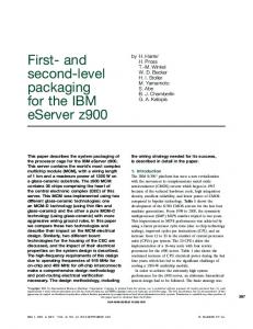
3. Matrix Inversion Core Generator Tool As shown in the previous sections, there are different solution methods for matrix inversion which can be implemented in many different ways. The selection of these methods depends on the structure of the given matrices. The implementation choices are: matrix size (depends on the number of antennas used in system), resource allocation, number of functional units, the organization of controllers and interconnects (depends on the hardware constraints such that designs which offer the most time efficient or the most area efficient architecture), and bit widths of the data (depends on the precision required). GUSTO, “General architecture design Utility and Synthesis Tool for Optimization,” is a high level design tool, written in Matlab, that is the first of its kind to provide automatic generation of different matrix inversion architectures. GUSTO allows the user to select the matrix inversion method (QR, LU and/or Cholesky decompositions), the matrix dimension, the type and number of arithmetic resources and the data representation (the integer and fractional bit width) as shown in Figure 1. The created architecture by GUSTO works at the instruction-level where the instructions define the required calculations for the matrix inversion. For better performance results, instruction level parallelism is exploited. The dependencies between the instructions limit the amount of parallelism that exists within a group of computations. GUSTO generates a general purpose architecture and its datapath by using resource constrained list scheduling. In this architecture, controller units track the operands to determine whether they are available and perform register renaming which assigns a free arithmetic unit for the desired calculation. Register renaming is
Fig. 1. Flow of GUSTO.
provided by reservation station usage in every arithmetic unit where reservation stations fetch and buffer an operand as soon as the operand is ready. Our proposed design consists of two controller units and three arithmetic units. The arithmetic units are capable of computing decomposition, simple matrix inversion using back-substitution and matrix multiplication. The control units are instruction and timing and operand controller. The arithmetic units are adder/subtractor, multiplier/divider and square root units. The advantage of this architecture is that it is capable of solving any of the decomposition methods with a selection input.
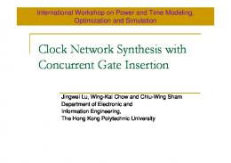
4. Results In this section, we first present the total number of operations used in different decomposition methods of GUSTO and determine different inflection points between these different methods; and compare our area and throughput results with previously published FPGA implementations. The total number of operations used in different decomposition methods is shown in Figure 2 in log domain. It is important to notice that there is an inflection point between LU and Cholesky decompositions at 4 × 4 matrices with a significant difference from QR decomposition. Furthermore, this inflection point is shifted to 5 × 5 matrices for matrix inversion implementations where LU and Cholesky have more significant differences in terms of total number of operations; besides the difference between QR and the other decomposition methods increases.
Total Number of Operations
10000
TABLE I COMPARISONS BETWEEN OUR RESULTS AND PREVIOUSLY PUBLISHED PAPERS. NR DENOTES NOT REPORTED. Ref[9] Ref[10] Our
Decomposition Based Matrix Inversion Decomposition Only
1000
Method
QR
QR
100
Bit width
12
20
20
10
Data type Device type
fixed Virtex 2
floating Virtex 4
Fixed Virtex 4
Slices DSP48s BRAMs
4,400 NR NR
9,117 22 NR
11,644 12 1
Throughput (106×s-1)
0.28
0.12
2
3
4
5
6
7
QR
LU
Cholesky
QR
LU
Cholesky
QR
LU
Cholesky
QR
LU
Cholesky
QR
LU
Cholesky
QR
LU
Cholesky
QR
LU
Cholesky
1
QR, LU, Cholesky
0.23
0.32
0.30
8
Fig. 2. Total number of operations in log domain for decomposition based matrix inversion (light) and decompositions only (dark). Note that the dark bars overlap the light bars.
We present area results in terms of slices and performance results in terms of throughput. Throughput is calculated by dividing the maximum clock frequency (MHz) by the number of clock cycles to perform matrix inversion. A comparison between our results and previously published implementations for a 4 × 4 matrix is presented in Table 1. For ease of comparison we present all of our implementations with bit width 20 as this is the largest bit width value used in the related works. Though it is difficult to make direct comparisons between our designs and those of the related works (because we used fixed point arithmetic instead of floating point arithmetic and fully used FPGA resources (like DSP48s) instead of LUTs), we observe that our results are comparable. The main advantage of our implementation is that it provides the designer the ability to study the tradeoffs between architectures with different design parameters.
5. Conclusion This paper presents different decomposition based matrix inversion architectures using a matrix inversion core generator tool, GUSTO, that is developed for automatic generation of various matrix inversion architectures which targets reconfigurable hardware designs. GUSTO provides different parameterization options including matrix dimensions, bit width and resource allocations which enables us to study area and performance tradeoffs over a large number of different architectures. In this paper, we especially concentrate on QR, Cholesky and LU decomposition methods for matrix inversion in a general purpose architecture, to observe the advantages and disadvantages of these methods in response to varying parameters.
6. References [1] L. Zhou, L. Qiu, J. Zhu, “A novel adaptive equalization algorithm for MIMO communication system”, Vehicular Technology Conference, Volume 4, 25-28 Sept., 2005 Page(s):2408 – 2412. [2] K. Kusume, M. Joham, W. Utschick, G. Bauch, “Efficient Tomlinson-Harashimaprecoding for spatial multiplexing on flat MIMO channel,”IEEE International Conference on Communications, Volume 3, 16-20 May 2005 Page(s):2021 - 2025 Vol. 3. [3] C. Hangjun, D. Xinmin, A. Haimovich, “Layered turbo space-time coded MIMO-OFDM systems for time varying channels”,Global Telecommunications Conference, 2003. IEEE Volume 4, 1-5 Dec. 2003 Page(s):1831 - 1836 vol.4. [4] A. Irturk, B. Benson, S. Mirzaei and R. Kastner, “An FPGA Design Space Exploration Tool for Matrix Inversion Architectures,” IEEE Symposium on Application Specific Processors (SASP) 2008. [5] L. Hanzo, T. Keller, “OFDM and MC-CDMA: A Primer,” Wiley-IEEE Press, 2006. [6] T. Kailath, H. Vikalo, B. Hassibi, “MIMO Receive Algortihms.” Space-Time Wireless Systems: From Array Processing to MIMO Communications. Cambridge University Press, 2005. [7] G.H. Golub, C.F.V. Loan, Matrix Computations, 3rd ed. Baltimore, MD: John Hopkins University Press. [8] C. K. Singh, S.H. Prasad, P.T. Balsara, “VLSI Architecture for Matrix Inversion using Modified GramSchmidt based QR Decomposition”, 20th International Conference on VLSI Design. (2007) 836 – 841. [9] F. Edman, V. Öwall, “A Scalable Pipelined Complex Valued Matrix Inversion Architecture”, IEEE International Symposium on Circuits and Systems. (2005) 4489 – 4492. [10] M. Karkooti, J.R. Cavallaro, C. Dick, “FPGA Implementation of Matrix Inversion Using QRD-RLS Algorithm”, Thirty-Ninth Asilomar Conference on Signals, Systems and Computers (2005) 1625 – 162.