Automatic Learning by Autonomous Driver Agents as Applied to Performing Realistic Lane Change Maneuvers Omar Ahmad*, Yiannis Papelis**, Sunil Bulusu, and Vijay Gade National Advanced Driving Simulator, The University of Iowa 2401 Oakdale Blvd., Iowa City, Iowa 52242-5003 *Tel: (319)335-4788 **Tel: (319)335-4597 Fax: (319)335-4658 *
[email protected] *
[email protected] Abstract High-fidelity driving simulators immerse a driver in a highly realistic virtual environment for the purpose of studying human driving behavior in a realistic yet safe setting. Many factors contribute to the immersive experience, but when the subject under study requires interaction with other vehicles, it is important that the virtual environment includes a microscopic traffic simulation model. Such a model often consists of populating the road network with one or more autonomous driver models. The more individual types of maneuvers an autonomous driver model exhibits, the more realistic it appears to the simulator driver. This paper focuses on the design of a specific behavior that is responsible for implementing lane change maneuvers. This behavior, which is part of a larger autonomous driver model, is important because it is necessary for building more complicated behaviors such as yielding, route planning, and merging. This behavior is unique in that it accommodates several conditions simultaneously and is designed to work with an arbitrary vehicle dynamic model. To address the variability in the physical response of different vehicle models, it uses an off-line learning technique that exercises the dynamic model and builds lookup tables that encompass the experience of the driver model. 1. Introduction Autonomous vehicles are an important component of the real-time scenario definition and control software at the National Advanced Driving Simulator (NADS). The experiments conducted at NADS require a realistic driving experience for the simulator driver. The quality of the driving experience relies in part on the amount of information available from the virtual environment and the sophistication of the objects modeled inside it. In that sense, a realistic traffic simulation is essential. In the NADS software model, traffic is made up of individual autonomous vehicles that interact with each other and with the simulator driver. Each vehicle utilizes a complete autonomous driver model that dictates its behavior. This paradigm is often referred to as microscopic traffic simulation. The number and realism of behaviors exhibited by autonomous vehicles determine how realistic the traffic in a simulation appears. The autonomous vehicles in the NADS software accurately exhibit several behaviors. This paper focuses on one such behavior—the lane change maneuver. It is challenging to model because the simulator driver can easily distinguish a realistic lane change maneuver from an unrealistic one. Performing a
realistic lane change maneuver requires accurate information from the virtual environment about the layout of the road network and the physical capabilities of the vehicle, in addition to various constraints that dictate the urgency with which a lane change maneuver is implemented. This paper begins with a brief description of the autonomous vehicle model used in the NADS. It then briefly describes the formalism used to model the driver behaviors. The core of the paper focuses on describing our work in determining the conditions that trigger lane changes. In addition, the paper describes the learning process through which any vehicle model can be controlled to perform realistic lane change maneuvers in a manner independent of the controlled vehicle's physical response. 2. Issues in Autonomous Driver Modeling A key design approach to the autonomous driver model is the separation between driver behavior and the physical vehicle model. This approach has several benefits. It allows the use of the same driver model with a wide variety of physical models that represent different vehicles such as passenger cars, sport utility vehicles, trucks, emergency vehicles, etc. Although cars and trucks are physically quite different, they use essentially the same behavioral logic to move around the road network and interact with other objects. Another reason for this separation is the need to provide realistic motion control for the vehicle controlled by the autonomous driver model. It has been our experience that when using simple equations of motion for controlling the motion of a vehicle, the visual aspect of the result is not pleasing and, in fact, looks rather artificial. For example, a braking car shows no pitching, there is no roll when turning, and slow-speed turns look unnatural. Using special effect equations to simulate these cues is often as complicated as developing physics-based models, so we decided to use a multibody physics-based model for the actual generation of motion for each vehicle. The result is natural-looking motion under various conditions. However, there is one disadvantage to using this approach. The response of such a vehicle is non-linear both in terms of velocity and steering, and it is therefore necessary to develop velocity and steering controllers. Such controllers can be tuned to perform acceptably even with modest variation in the baseline characteristics of vehicles (e.g., weight, horsepower). However, one has to decide at what level to separate the physical control of the vehicle from the higher level driver model. For example,
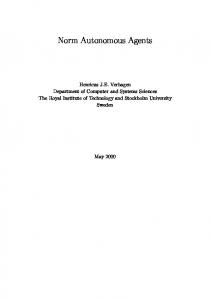
consider the high-level decision to stop at a particular point on the road. One approach may be that the dynamic model simply accepts gas pedal displacement commands, in which case the responsibility of physical control lies with the driver model. Another approach may be to design the dynamic model with a built-in controller that accepts a desired acceleration and then calculates the gas pedal displacement. This somewhat separates the physical control from the driver model; however, the driver model needs to be aware of the controller and vehicle capabilities to ensure that it provides achievable commands. An example of the problems that occur when the driver model is not aware of the physical model capabilities is a situation in which the driver model waits too long to provide a braking command and the target point is overshot. Clearly, there are many ways to address this issue, all of which have advantages and disadvantages. Our approach to building an integrated driver model is to remove most of the low-level control responsibilities from the driver model and place them with controllers that are tightly integrated with the dynamic model. That way, controllers can be tuned to the dynamic model, and unlike the driver model that may run at a lower frequency, the controllers can run at the same frequency as the dynamic model. The input to these controllers consists of velocity and steering commands. A steering command is delivered as a target point, and velocity commands are delivered using two distinct formulations. The first formulation provides a desired velocity and a distance by which this velocity has to be achieved, and the second formulation provides another object and a desired following distance to that object. The steering command is equivalent to providing a steering angle; however, providing a target point is simpler from the driver model's standpoint because it makes lane-tracking straightforward. Similarly, even though the target velocity and distance formulation is equivalent to providing acceleration, it is easier to use when the goal is stopping at a fixed point on the road. Our driver model still has to cope with the capabilities of different dynamic models. Such information is critical in numerous decision-making situations involved in driving. For example, consider the situation illustrated in Figure 1. Vehicle A is waiting to cross the intersection while traffic (Vehicles B and C) is crossing on the perpendicular road. There are numerous models that describe human behavior in such gap-acceptance situations, which we can consult to select an appropriate gap. However, such gap-acceptance figures are relative safety margins, not absolute numbers for the spacing between vehicles. For example, one can make a simple imaginary experiment where the same human driver is placed in the situation depicted in Figure 1 but with two different types of vehicle—first with a typical passenger car and then with a slower and larger truck. Clearly, some gaps that the driver will decide to take when driving the car would be let go when driving the slower truck. The reason for this difference is that the performance of the vehicle is an integral part of the driver's decisionmaking process.
Veh B
Veh C
Veh A
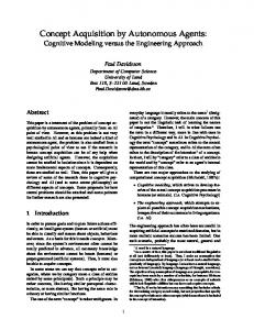
Figure 1 – Gap acceptance example. One can find numerous similar situations when the same driver acts somewhat differently depending on the type of vehicle they are controlling, even when their highlevel behavior is the same. Lane-tracking, for example, is a characteristic of the driver, not the car. If a driver likes to stay on the right side of a lane, he or she will apply any control inputs necessary to drive that way. In a different car, the control inputs would be slightly different, but the vehicle placement would be similar. In effect, different drivers adapt, or learn how to apply their desired driving characteristics to any car they drive. This observation led us to design a driver model that can also adapt, or learn how to control a vehicle, by exercising a vehicle, observing the response, storing that information, and then using that information while making decisions during driving. In this context, the learned information involves the ability to predict the non-linear response of the vehicle dynamics model. Note that if the dynamic model was a simple linear model, there would be no need for learning in the sense that a few closed-form equations could be used to quickly predict the response. However, when using nonlinear multi-body dynamic models, such learning is necessary and becomes an integral part of the overall autonomous driver model. 2. The Autonomous Vehicle Model Figure 2 illustrates a high-level block diagram of the overall model. The block diagram has been somewhat simplified to allow focus on the lane change maneuver; however, enough information is included to provide a better understanding of the framework within which the lane change maneuver operates. As described earlier, the key characteristic of the model is the separation between the dynamic model and associated controllers and the behavioral model. Another key characteristic of the model is that it uses concurrency to deal with the implementation of multiple goals and satisfaction of multiple constraints. Specifically, the Control Inputs Fusion Logic block illustrated in Figure 1 is responsible for receiving the control inputs from multiple submodels and determining how to fuse such inputs. The output of the fusion block is then directed to the
by sending run-time instructions to the autonomous vehicle during the simulation. Autonomous vehicles display the following major behaviors: lane-tracking, following other vehicles, lane changes, avoiding collisions with oncoming vehicles, and navigating intersections. Each of these major behavior categories encapsulate several other behaviors and functionalities. For instance, the lane-tracking behavior encapsulates the following functionality: keeping the vehicle positioned in the center of its lane, obeying speed limits, slowing down on curves in the road, and obeying external commands to control the vehicle’s velocity. Due to limited space, we omit further details of the overall vehicle model. Readers are urged to refer to Ahmad & Papelis (2000) [2] and Papelis & Ahmad (20001) [3] for more details.
dynamics model. The vehicle’s behavior model has been implemented using the Hierarchical Concurrent State Machine (HCSM) formalism [1]. This formalism allows us to model the behavior of a vehicle as a tree of state machines where each part of the tree implements a separate behavior. The execution semantics of HCSM allow us to easily implement hierarchical models with built-in concurrency. A detailed description of the HCSM formalism is beyond the scope of this article, however, Section 5 provides the design for the HCSM subtree that is responsible for implementation of the lane change maneuver. The autonomous vehicle has the ability to move around the road network and perform normal traffic operations on its own. Autonomous vehicles can also be instructed to move around the road network on a pre-defined path or perform specific actions during the scenario design or Virtual Environment Manager Road Network Database
x, y, z vel, acc
Dynamic Object Management
Free Driving Velocity Planning Route Planning
Lane Tracker
Driver Characteristics
Targ Pos
Random Pertrubation Speed Limit Estimator Curvature Induced Speed Limiter
Scenario Control Overrides
+
60 Hz
Obj Follow Logic
Survey and Classificatio n of Other Vehicles
Steering Controller
Targ Vel & Dist
Driver Characteristics
Targ Pos Targ Pos
Lead Vehicle Identification
Vehicle Dynamics Model
Min
Follow Behavior
Targ Vel & Dist
Control Inputs Fusion Logic
Velocity Controller
Targ Vel & Dist Follow Obj
Tactical Follow Controller
Lane Change Logic
Learned Capabilities Lane Change Condition Computation
Follow Mode Select
Performance Initiate command Lane Tracker
Targ Pos
Rules of Road
Traf Sign Logic
Vehice Dynamics accel
60 Hz Obj Follow Logic
Intersection Logic
Traf Light Logic
steer angle
Targ Vel & Dist Resolution/ Selection
Merge Logic
Figure 2 – Autonomous driver model block diagram.
3. Lane Change Maneuver The lane change model is responsible for determining whether a lane change is necessary and then providing guidance for implementing the actual maneuver. Note that the interaction between the lane change logic and the fusion logic is bi-directional. The lane change logic continuously provides to the fusion logic the necessity or ability to perform a lane change and associated performance data. The fusion logic in turn uses this information to determine if and when to commit to a lane change. Once the commitment is made by the fusion logic, the lane change implements the maneuver by utilizing existing parts of the model. For example, the lane change model utilizes the lane tracker and object follower while implementing the lane change. Lane changes can be initiated for a many reasons. These reasons are ordered by priority. Zero or more of these reasons may be true at any given moment. For example, a vehicle may be traveling in the middle lane of a threelane highway. There may be a slow-moving vehicle in front of it and thus it would want to move to the left lane to pass. At the same, this vehicle’s exit may be approaching and thus the vehicle would want to move the right lane to take the exit. In this case, the vehicle would perform the lane change to the right to stay on its path because that has higher priority. The lane change logic submits the highest priority lane change performance information to the fusion logic, which is responsible for deciding whether the maneuver will be initiated. One condition that must always be met is gap acceptance. For lane changes, gap acceptance is measured against four parameters. The first two parameters are the time to collision with a leading vehicle or with a following vehicle. The time to collision is computed using bumper-to-bumper distances. The last two conditions are the absolute bumper-to-bumper distances to the leading and following vehicles. Different thresholds can be used for these four parameters, based on the urgency of performing the maneuver or the need to accommodate specific driving styles. The following sections provide each of the conditions computed by the Lane Change Condition Computation block. They are referred to as "Reasons" to separate them from the various associated subconditions, which for brevity are referred to as "conditions."
• Condition 3: The current distance to the intersection is within five times the estimated forward distance needed to complete the lane change
Reason 1: Path guidance Route planning determines a route that the model follows while navigating the road network. Often times, a lane change is necessary before reaching an intersection to ensure that the route can be followed. The following subconditions are evaluated:
• Condition 1: The autonomous vehicle should be on a highway on-ramp.
• Condition 1: The vehicle’s current lane does not lead to the intersection corridor needed to traverse the next intersection. • Condition 2: The Estimated Time to Arrival (ETA) at the next intersection is within a threshold time, or the actual distance is within a threshold distance.
• Condition 4: The target lane has proper gap among existing traffic, if any. If Condition 4 fails and the distance to the intersection is less than the distance needed to complete the lane change, the lane change maneuver reports back to route planning, which then generates a new route. Reason 3: Losing lane at upcoming intersection Upon encountering an intersection which contains two or more corridors that merge into one, as shown in Figure 3, the autonomous vehicle has the option to make a lane change. When possible, the autonomous vehicle changes lanes to ensure a smooth transition into the next lane. Before making a lane change, the following conditions must be satisfied: • Condition 1: On the autonomous vehicle’s path, there exists an intersection which merges two or more corridors into one. • Condition 2: The autonomous vehicle is located on or headed toward the corridor that will be merged into another corridor. • Condition 3: The ETA at the merge point is within a threshold time, or the actual distance is within a threshold distance. • Condition 4: The current distance to the intersection is within five times the estimated forward distance needed to complete the lane change • Condition 5: Target lane gap acceptance.
Figure 3 - Losing corridor at upcoming intersection. Reason 4: Highway merge When entering a highway, an autonomous vehicle has the option to make a lane change onto the highway or to simply follow the corridor into the highway. When possible, an autonomous vehicle performs a lane change to ensure a smooth entrance onto a highway without any braking. Before making a lane change for this reason, the following conditions must be satisfied:
• Condition 2: The autonomous vehicle should have a minimum velocity of 35 mph. • Condition 3: Target lane gap acceptance. Reason 5: Lane change sign Upon encountering any sign whose interpretation indicates that the current lane will be terminated, the autonomous vehicle has to make a lane change. The direction of the lane change (left/right) is dictated by the sign. Note that this reason is similar to Reason 4; however, this reason is utilized to better model lane changes implemented in anticipation of a lane change,
as opposed to observation of the loss of lane. In fact, studies [4] have shown that lane changes due to signage can have a negative effect on traffic flow, and incorporating this into the model allows it to better capture such effects. The following subconditions are evaluated:
• Condition 1: There is a vehicle in front of the autonomous vehicle that is stopping or is moving at most 10 mph and not more than 90% of the autonomous vehicle's velocity.
• Condition 1: The autonomous vehicle should be on a highway.
• Condition 3: Target lane gap acceptance.
• Condition 2: There should be a construction sign, and the autonomous vehicle should in the same lane as the sign. Furthermore, the autonomous vehicle’s distance along the road should be somewhere between the sign and the distance afterward that the sign specifies. • Condition 3: Target lane gap acceptance. Reason 6: Move into non-passing lane An autonomous vehicle monitors the roadway to make sure it stays in the non-passing lane on highways when not passing other vehicles. Before making a lane change for this reason, the following conditions must be true: • Condition 1: The autonomous vehicle should be on a highway, and there should be a lane to the right moving in the same direction as the current lane. The lane to the right should not be an off-ramp. • Condition 2: The autonomous vehicle did not previously complete a lane change for path guidance. • Condition 3: At least 2 seconds have expired since the completion of the last lane change. • Condition 4: Target lane gap acceptance. Reason 7: Slower vehicles On roads with more than one lane traveling in the same direction, the autonomous vehicle changes lanes into the passing (left) lane when there is a slower moving vehicle ahead of it. Before making the lane change, the following conditions must be true: • Condition 1: There is a vehicle in front of the autonomous vehicle that is moving at least 10 mph and at most 90% of the autonomous vehicle's velocity. • Condition 2: At least 3 seconds have expired since the completion of the previous lane change. • Condition 3: There exists a lane to the left of the current lane that is traveling in the same direction. • Condition 4: The next intersection is at least 300 m away. • Condition 5: Target lane gap acceptance. Reason 9: Very slow moving or stopped vehicle This lane change is very similar to the Slower Vehicle Lane Change except that it applies to very slow moving or stopped vehicles in front of the autonomous vehicle resulting in a unique set of choices for gap accept thresholds and urgency of the maneuver. This maneuver is often called the "Flying Pass." Before making this lane change, the following conditions must be true:
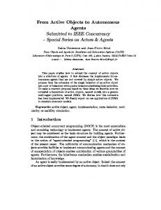
• Condition 2: There exists a lane to the left of the current lane that is traveling in the same direction. Reason 8: Avoid merging vehicles On highways, the autonomous vehicle looks for merging on-ramps. If there are vehicles merging onto the highway, the autonomous vehicle moves into the passing lane to let those vehicles onto the highway. Before making the lane change, the following conditions must be true: • Condition 1: The autonomous vehicle should be on a highway lane that has an on-ramp merging with it. • Condition 2: There exists a lane to the left of the current lane that's traveling in the same direction. • Condition 3: There is at least one vehicle approaching in the merge lane, and its ETA at the current road is within 4 seconds of the ETA of the current vehicle. • Condition 4: Target lane gap acceptance. 4. Vehicle Response Learning There are two cases where information about the physical model is critical in the implementation of the lane change logic. The first case is when determining the feasibility of performing a lane change, and the second is the actual implementation of the maneuver. In determining the feasibility of a lane change, the behavioral model needs to know how much time or distance it will take to perform the lane change. As already discussed in Section 2, this performance information relies heavily on the response of the vehicle dynamics to the control inputs. The actual implementation requires providing a proper guiding point to the steering controller. Unfortunately, one cannot simply provide a step steering input because it could lead to oscillations or instabilities. Our approach to addressing these issues is to break down the lane change maneuver into smaller maneuvers that can be separately analyzed and then exercise the dynamic model to obtain the limits of performance while implementing these submaneuvers. During the exercise implementation, the actual performance is measured and the results are stored in a database that can be consulted at runtime. The final database can be used by the driver model both to determine the maximum performance maneuver achievable at a given time and, once a decision is made, to obtain the control inputs that would produce the maneuver. The lane change maneuver has been broken down into three phases illustrated in Figure 4. The first phase is the entry phase, marked as ENT. During that phase, the steering controller is given an initial step angle, and in following iterations the desired angle is the difference between the initial step input and the current orientation of the vehicle. At the end of the maneuver, the vehicle is
traveling along the orientation of the step angle. The second phase is the straight segment, marked as STR in Figure 4. The steering controller is fed a zero turn. The last segment, marked EXT in Figure 4, is the reverse of the first segment where the same step angle is fed to the steering control, but with opposite sign. EXT
STR ENT
Figure 4 – Lane change decomposition. It is known from control theory that the response of a dynamic system to a step can lead to another stable state, oscillations, or instability. Even when the system reaches a stable state, the amount of time to reach stability depends on the system itself and on how stability is defined. In this case, the vehicle is stable when it reaches the target orientation with oscillations diminished below some threshold. Furthermore, for practical reasons, we are only interested in the cases where stability is reached before the vehicle's lateral travel is less than about a lane's width. To develop the capabilities database, each vehicle model is first driven along a straight line until it reaches a target speed. At that point, a step steering input is applied and the behavior is measured. If the system stabilizes within a lane's width or so, the actual longitudinal and lateral distance travel is recorded and the process is repeated for a larger step input. If the system is unstable, oscillatory, or does not stabilize quickly enough, the angle used as the step input is set as the performance threshold for the given speed. Once the performance limit is determined, the same process is applied but for a higher longitudinal velocity. At the end of this process, the database contains a large lookup table that can be used to determine the maximum step input that can be fed to the steering controller at any given velocity and the amount of lateral and longitudinal travel that the vehicle will cover while responding to the step input. Given this information, the lane change logic can easily compute the aggregate travel of the vehicle, considering that the overall lane change maneuver contains two step inputs that are symmetric and one straight driving segment for which the travel can easily be computed using time-distance equations. The information in the database can be used multiple ways. For example, it can be used to determine whether a lane change is possible at a given speed given the amount of space available on the road ahead. If space is not a concern, an aggressiveness parameter can be used to select how sharp a lane change to implement at each speed. In all cases, using lookup tables is computationally efficient, something that is critical when running in real-time. 5. The LaneChange HCSM In addition to determining the feasibility and implementing the maneuver, there are other issues that
the model should support. These include controlling turn signals, re-evaluating conditions, and aborting when necessary. As mentioned earlier, the system is implemented as an HCSM. The LaneChange HCSM extends the basic functionality described in this paper by providing persistent state information. As shown in Figure 5, the LaneChange HCSM has the following modes: • Monitor. In this mode, the model continuously evaluates the various lane change reasons and reports back to the Control Input Fusion component. • Signal. Once the command is received to implement a lane change, the vehicle begins signaling. • Execute: While this state is active, the model implements the lane change. • Abort. This mode is reached when an ongoing lane change has to be aborted because the conditions have changed. This state is necessary to accommodate the continuously evolving state of the virtual driving environment. LaneChange
Monitor
Signal
Execute
Monitor
Monitor
Abort
Figure 5 – The LaneChange HCSM. 6. Conclusion This paper described a lane change model used within a larger autonomous driver model used in driving simulator applications. The model uses physics-based vehicle dynamics for motion prediction. To accommodate the varying response of various vehicles, the system utilizes an off-line process that exercises the model and stores the response in a database that is consulted at runtime to support decision-making and maneuver implementation. 7. References [1] Cremer, J., Kearney, J., & Papelis, Y. (1995). HCSM: A Framework for Behavior and Scenario Control in Virtual Environments. ACM Transactions of Modeling and Computer Simulation, 5(3): 252-267. [2] Ahmad, O., & Papelis, Y. (2000). An Autonomous Driver Model for the Overtaking Maneuver for Use in Microscopic Traffic Simulation. Paper presented at the Driving Simulation Conference 2000. Paris, France. [3] Papelis, Y. & Ahmad, O. (2001). A Comprehensive Microscopic Autonomous Driver Model for Use in High-Fidelity Driving Simulation Environments. Paper presented at the Transportation Research Board Conference. Washington, D.C., USA.
Author contact information: Yiannis Papelis National Advanced Driving Simulator The University of Iowa 2401 Oakdale Blvd. Iowa City, Iowa 52242-5003 (319) 335-4597 (319) 335-4658 FAX
[email protected] Omar Ahmad National Advanced Driving Simulator The University of Iowa 2401 Oakdale Blvd. Iowa City, Iowa 52242-5003 (319) 335-4788 (319) 335-4658 FAX
[email protected]