1
Accepted for publication in Optical Engineering (2002)
Automatic object identification irrespective of geometric changes
José L. Pech-Pacheco1, Josué Alvarez-Borrego2, Gabriel Cristóbal1 and Matthias Keil1
1
Instituto de Óptica (CSIC), Depto. De Óptica, Daza de Valdés, Serrano 121, 28006 Madrid, Spain 2
Centro de Investigación Científica y de Educación Superior de Ensenada, División de Física Aplicada, Departamento de Óptica, Km. 107 Carretera Tijuana-Ensenada, Ensenada, B. C., México
[email protected]
Subject terms: scale transform,
image processing, invariant correlation
function.
1
2
Abstract This paper presents a new approach to achieve object identification based on the use of phase correlation in the scale transform domain for automatic character recognition albeit the results are extensible to other fields. The proposed method is shown to be invariant to translation, rotation and scale. We extended the methodology used by Casasent and Psaltis1 by considering a more efficient digital scale transform as an alternative to the Fourier-Mellin techniques. In order to improve the discriminative power, we introduced a new template matching based on the use of a modified weighted log-polar spectrum. The correlations have been calculated by using phaseonly filters (POF) in a digital system. The proposed method is able to provide discrimination between scale and rotation in images to facilitate image registration.
2
3
1 Introduction A classical approach to image recognition is the correlation technique, also referred to as template matching. Correlation process of a target image is a way to look for other images that are similar to the target. Shifting the target to every location in the image does correlation in the spatial domain. When the image dimensions are large, this process is very inefficient. Usually the correlation is performed in the Fourier domain where we can apply the convolution theorem.
Pratt2 pointed out the two main tradeoffs of the
correlation process: the broadness of the correlation peaks and sensitivity to noise. Chen3 extended the list of tradeoffs including the sensitivity to feature shape, to size and to orientation. All of these problems increase the difficulty in the localization and identification of correlation peaks. The classical matched filter
4,5,6
is used for determining the presence of a
known image in a noisy scene. One limitation of the matched filter is that the filtering output is primarily dependent on the energy of the input images rather than on their spatial structures.
This is why matched filtering provides a
relatively poor discrimination between objects of different shapes, which are similar in size or energy content.
Another problem is that the correlation
output presents difficulties in locating precisely the correlation maximum, which corresponds to the image translation. Nevertheless, this problem can be solved using a phase-only filter (POF).
3
4
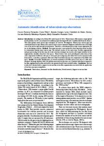
A POF can be used for detecting expected objects in an input image. Since only the spectral phase of the filter function is used for matching, the filtering output between two identical but translated images yields a much sharper peak than the classical matched filtering does, which makes the detection of the maximum and the location peak much easier. The POF is an accurate and efficient matching method for image identification and discrimination of similar objects. When the correlation process is extended to rotation or scale’s change of the objects, phase only matched method becomes rather inefficient (Fig. 1). Figure 1a shows the scale’s change effect of the letter E using POF.
Size
variations go from 100% to 200% (x-axis) and the correlation values from 0 to 1 (y-axis).
It is observed that with a change of 10% in the scale, the
correlation value decreases to 35% of its maximum value, and when the scale increases (100%), the correlation value decreases to 10% of its initial value. This effect is also observed in the variation of rotation of the letters, as it can be seen in figure 1b.
In this figure, the decline is not so abrupt like it is
compared to the scale. These correlation results suggest a need for the development of new methods providing invariance in position, rotation and scale of the objects to be identified.
By using scale and rotation like additional criteria for object-
classification we make the whole process more reliable. A paradigm demonstrating the importance of invariances in object recognition is the study presented by Soon et al.7 for image recognition. They found that changes in
4
5
rotation pose a hard-to-tackle problem for all systems that deal with pattern recognition. This holds both for electronically and optical implementations. In this study we developed an identification technique invariant to position, scale and rotation for similar images (E, F, P, H) and different images (A, B, C) with the purpose of being able to use this system as a more general classification scheme in the near future.
A good application is to identify
biogenic particles in sea water samples, for example there are some studies in the present time which are emphasizing in these directions8-11.
In this type
of applications is very important to consider the invariance to scale and to rotation of the images, because for example, in phytoplankton species exists a maximum of 15% of difference in size in adult organisms of the same species and in a sea water sample the organisms present different positions and rotations.
Therefore, considering the scale and rotation invariance we
wish to identify organisms of one specie does not matter if there exists difference in size or rotation when the target is compared with other organisms. In this paper, we take care of several important points; first, all the process is digital only, numerical simulation were performed in order to correlate the target with the different images. Second, to start the analysis from the modulus of the Fourier transform of the image, this will give us the invariance in the correlation process to the position; Third, the enhancement of high frequencies because we obtain more detailed information of the contour of the image to be recognized; Fourth, to use the scale transform because is insensitive to scaling and rotation. In this way we use the scale transform
5
6
properties for image identification and registration.
All these points in the
image analysis will give us a phase-only filter with the characteristics of being invariant to scale, rotation and position in the correlation process. This paper is structured as follows.
In section 2, we describe all the
processes involved in one invariant correlation system.
In section 3, we
present some examples. Finally in section 4, we summarize and discuss our invariant system implementation.
2 Invariant correlation At present, there exists many approaches that tried to solve the problem of object-classification and object-recognition regardless of location, scale and rotation of the candidate-objects. There are techniques based on circular harmonic filters (CHF) that were applied by Zavala-Hamz and AlvarezBorrego8 which possess some independence of rotation, but are not invariant with respect to scale. Another approach is the log-polar transformation, which was developed by Casasent and Psaltis1.
This work is considered as a
milestone for the development of pattern-recognition systems which are supposed to possess invariance with respect to translation, rotation and scale. The method turned out to be efficient in the recognition of phytoplankton, see e.g. Pech-Pacheco and Alvarez-Borrego9.
In this study the authors
presented an optical-digital implementation of the log-polar transformation with a good recognition performance.
6
7
At the same time we present some improvement by providing results with a better localization of the candidate object. By doing so we achieve translationinvariance to some degree. In this paper we introduce the scale transform12-13 in the correlation process due its invariance to size and rotational changes.
If we call c the scale
variable then scale transform and its inverse is given by
∞
1
D (c ) =
2π
f ( x) =
1 2π
∫ f ( x)
e − jc ln x x
0
∞
∫ D (c )
e jc ln x x
−∞
dx , dc ; x ≥ 0
(1)
.
(2)
The scale transform can be written as D (c ) =
1 2π
∞
∫ f ( x) x
− jc −1 / 2
dx , (3)
0
which shows that it is the Mellin transform with the complex argument –jc+1/2. A practical realization of the Mellin transform is given by a logarithmic mapping of the input scene followed by a Fourier transform.
Since we are
dealing with the Mellin transform of a complex argument, there exists a direct relationship with the Fourier transform. In particular if we define a signal f l ( x) =
1 x
f (ln x) then by substituting in Eq. 1 we have
Dl (c) =
1 2π
∞
∫ f ( x )e
− jcx
dx, (4)
−∞
7
8
that is
F(c) = Dl (c)
F , where
is the symbol for Fourier transform. From this
relation one can see the scale by resampling the samples uniformly distributed of x with a logarithmic function. A non-separable direct 2D scale transform
D(cr , cθ )
is used in this correlation
process because it is invariant to size and rotational changes, and is given by:
D(c r , cθ ) =
1 2π
∞
2π
0
0
∫ ∫ f (r ,θ )r
− jc r −1 / 2
and taking the log of the radial coordinate D(cλ , cθ ) =
1 2π
∞
2π
0
0
∫ ∫e
λ /2
e − jcθ θ drdθ ,
λ = ln(r )
(5)
we get
f (λ ,θ )e − j ( λcr +θcθ ) dλdθ .
(6)
Figure 2 shows our method step by step. Figure 2a shows the original image f ( x, y ), consisting of the image of the letter E. Figure 2b shows the modulus of the Fourier transform of Figure 2a.
An enhancement of high frequencies
(Fig. 2c) is applied to this modulus. Here we compensated the characteristic drop-off of the modulus with high frequencies by applying an inverse decay filter. This results in an enhancement of the modulus at high frequencies (we enhance high-pass filtering effect which consists
to applying a parabolic
function to the modulus of FFT. In this way, low frequencies are attenuated and high frequencies are enhanced in proportion of wx2 , w 2y ). Consequently, the effective weigthing filter applied is
r and by using this we obtained the
8
9
maximum reliability in the classification-procedure. Once this effect is applied, the modulus presents a shape as it is observed in figure 2d where we can see the high frequencies in a more significant manner, which is going to help us to obtain a good identification of the object to be recognized. factor,
Then the scale
r (Fig. 2e), is applied to the image of figure 2d (r is the radial spatial
frequency, the origin of which lies at zero frequency in the optical representation of the Fourier-spectrum).
This process is what differentiates
the scale transform from the Mellin-transform. The effect of this factor on the module of FFT is radial only. After these steps, we mapped the cartesian coordinates (Fig. 2f) to polar coordinates (Fig. 2g). In this step we introduced a bilinear interpolation of the first data of coordinates conversion. done to avoid the aliasing due to the log-polar sampling.
This is
Figure 2h shows
the image in polar coordinates, (using logarithmic visualization), which is going to facilitate the identification invariant to scale and rotation. This image (Fig. 2h) is the one that is going to be correlated with the classical filters or with the phase-only filters, but in these cases the filters are invariant to position, rotation and scale.
3 Results 3.1 Discrimination of similar images In order to know if the method of identification does a good job, we need to know first if the system is able to discriminate between similar objects.
9
10
To do so, we selected the letters E, F, P and H, all of which had the same font-size and the same font-style. In figure 3, we can see the corresponding correlation among the different letters and the POF of the letter E. Figure 3a shows the autocorrelation of the letter E.
The graphic of the
correlation results is typical for the phase correlation type: a narrow peak with no side-lobes. Figure 3b shows the correlation of the letter F with the POF (letter E).
The
cross-correlation value is 0.27 . This indicates that the letter F is only 27% similar to the letter E.
The non-invariant correlation value of POF (letter E)
with the letter F is of 0.78. This indicates that the letter F differs by 22% from the letter E. Therefore, our methodology discriminates more efficiently. Figure 3c shows the correlation of the letter P with the POF (letter E). cross-correlation value is 0.16 .
The
This indicates that the letter P is only 16%
similar to the letter E and its discrimination is of 84%.
The non-invariant
correlation value of POF (letter E) with the letter P is of 53%.
Again, our
methodology discriminates better. Figure 3d shows the cross-correlation of the letter H with the POF (letter E). The cross-correlation value is 0.22 .
This indicates that the letter H is only
22% similar to the letter E and its discrimination is of 78%. The non-invariant correlation value of POF (letter E) with letter H is of 48%.
Therefore, the
discrimination value is 52%; again, this means that our methodology discriminates better.
10
11
3.2 Identification of letters of different rotation and scale. To test our method with respect to change of rotation and scale of the letters, cross-correlations of different letters (F, A, B and C) were calculated with the POF (letter E). The registration of the difference of rotation and scale of the letters to be identified was also done in this test. Correlation values obtained with the POF (letter E, size of 100%) and the images of the letter E for different scale are shown (Fig. 4a). The images of the letter E were varying from 50% to 150% in scale with respect to the letter E in its original size. The x-axis shows the scale variable (in percent).
The y-axis represents the
correlation values. The minimum value obtained in figure 4a was 0.43 with a difference in scale of 50%.
This means that, according with the defined
threshold-criterion, we can consider our approach to be scale-invariant with a threshold of 0.4 . Figure 4b visualizes the individual locations of the correlation peaks while varying the scale of the image. It can be verified that this variation only occurs parallel to the x-axis. In the log-polar-transformed image, variation in scale maps to displacement along the log(r) axis (Fig. 2h). Or stated the other way round, if we knew the position of the correlation peaks in the correlationplane (as in Fig. 4b), we can infer the according scale. In this representation we can observe that the values of pixels are lying in the interval from 110 to 160 while the scale varies from 150% to 50%. The central value (129, 129) corresponds to the correlation peak when there is no difference in size between the letter to identify and the letter of the filter (i.e., the reference size
11
12
of 100%). As the size of the image decreases, the displacement of the peak proceeds towards the right. This means it goes from 129 to 160 along the xaxis and afterwards, when the scale varies from 150% to 100%, the location of the peak varies from 110 to 129 along the x-axis.
Thus we have an
unambiguous position-scale relation at our disposal. In figure 4c we present the results of the correlation of the POF (letter E) with rotated versions of the letter.
The rotation angle is plotted along the x-axis.
We calculated the correlation (y-axis) for rotation-angles from 0o to 90o in steps of 5o. In the graphics we observe a decline in the correlation value to a minimum of 0.4. This effect can be attributed to the highly discriminative characteristics of the phase-only filters (i.e. they respond very sensible to small changes in the image).
Again if we consider a threshold value of 0.4
we can consider our system as invariant to rotation. Figure 4d shows the locations of the individual correlation peaks of figure 4c. While varying the angle of rotation, correlation peaks go in the y-axis direction. If there is no rotation, our peak will be found at the position of (129,129). If we rotate clockwise our values will vary from 129 to 85 pixels. The total interval covered goes from 80 to 213 pixels. For rotation-angles greater than 55o the correlation-peak is shifted to pixel 213 (y-axis). In this way we get a relation between rotation of the image and the location of the correlation peak. Comparisons among the results of the POF(letter E) with itself and with the letters F, A, B and C are shown (Fig. 5).
We can see that our method
discriminate very well considering a threshold of 0.4 .
12
13
In order to consider why 0.4 is a good threshold value for letter E or other cases we need to consider the spectral window in the sample theorem. We know that sample interval “a” and the data number “N” is so important in order to analyze the Nyquist frequency and the possible noise in the low frequencies. For this case, the two dimensional window can be written like: w( x, y ) = comb ( x, y ) rect( x, y ), where comb( x, y ) = comb( x ) comb( y ), and comb( x ) =
+∞
∑ δ( x − na),
n = −∞
comb( y ) =
+∞
∑ δ( y − ma ),
m=−∞
respectively. The rect(x,y) function is defined like rect( x, y ) = rect( x ) rect( y ), where N x − 1 for 1 ≤ x ≤ N 2= rect( x ) = Π x N 0 for another int erval N y− 2 rect ( y ) = Π y N
1 for 1 ≤ y ≤ N = 0 for another int erval
13
14
and N is the number of data in the window and for this particular case we consider a square window. So, w( x, y ) =
+∞
+∞
∑ ∑
δ( x − na) δ( y − ma ) rect( x ) rect( y ),
n = −∞ m = −∞
w( x, y ) =
N 2
N 2
∑ ∑
δ( x − na ) δ( y − ma ).
N N n =− m= − 2 2
Now, the Fourier transform of w(x,y) is W (f x , f y ) = N 2
sin c(Naf x ) sin c (Naf y ) sin c (af x ) sin c (af y )
,
where fx, fy are the frequencies in x and y axis respectively. Now, my discrete signal can be written like: gˆ( x, y ) = g( x, y ) w( x, y ), where g(x,y) is the continuos signal and w(x,y) is my sample window. From the convolution theorem we have ˆ ( f , f ) = G(f , f ) * W ( f , f ), G x y x y x y ˆ will look like G if W where the asterisk means convolution operation. So G looks like delta functions. In our case, figure 6 shows a profile of W in x-axis where we can see the noise in the low frequencies and bigger frequencies when we have images over 150% in scale. This is because scaling the image is similar to change the sample interval “a” in the discrete sample. For this reason we have considered that 150% is the upper limit in our methodology
14
15
for recognizing the object over a value of 0.4 . In the another case, reducing the scale implies to reduce information of the high frequencies because the Nyquist frequency changes. For this reason we have considered as the lower limit up to 50% of scaling change with respect to the target. Figure 7 show, for example, how the images look when we have reduced the scale below 50% with reference to the target. High frequency information is lost when the scale is reduced. So, our limits in this methodology is from 50% to 150% considering a target of 100% in scale. From these limits we have obtained the 0.4 value like threshold. Our results showed above (Fig. 5) justify this value. The estimate scale changes is given by the ratio 0.5/1.5=0.33, of this way, the 0.4 value indicates that experimentally is proved that this method gives a confidence value bigger than estimated. The image in figure 8a shows three letters at different angles of rotation, but with the same scale for each of the three letters. In figure 8b, the correlationgraph of the invariant identification system is presented. peaks are indicated with arrows.
The correlation
In this graphic we can observe that along
the y-axis there is no displacement of the correlation peaks.
This gives us
the information that the letters do not present any variation in size.
On the
other hand, we observe that the peaks are distributed along the x-axis, which indicates that the letters present differences in the angles of rotation and these differences are reflected in the locations of the correlation peaks. In the same way, figure 9 shows the result when we have three images with different scale.
Three peaks in the y-direction are shown. Each one
represents the scale involved in the letters.
15
16
An application of our system can be with medical images. To provide a good picture of the inside of the body, one might decide to fusion images of different types (e.g. MRI and X-rays). However, these images are seldom in exact register with respect to scale and orientation. So, if we want to fuse such images, we will have to discount scale, rotation and translation in order to achieve an unambiguous mapping between the spatial positions of both images. To do so, we might have some reference images, for example the bones of a healthy subject, and determine the maximum correlation with the region of interest. Of course, for each type (X-rays, MRI) we need a corresponding reference image.
4 Conclusions Our system is digital only, and this may be an advantage considering the rapidly development of fast hardware. This may enable identification in realtime. Hybrid systems, on the other hand (composed of an optical and a digital part), possess the disadvantage that they can not be handled as easily as digital systems and are more costly to implement. The features of our system of invariant identification are: 1) The enhancement of high frequencies, using this particular filter, which emphasizes the high frequencies of a power spectrum without affecting the low frequencies.
This process thus makes the complete spectral
information available for the correlation process. Or, stated differently, all the information of the image has roughly the same degree of importance
16
17
2) Interpolation of the polar-rectangular mapping.
This process has the
characteristic of avoiding aliasing, which might be present at low spatial frequencies. Some authors (Milanese and Cherbuliez14) utilize a lowstep-filtering to overcome the problem of aliasing (which includes the loss of information at these frequencies), which may lead to a higher probability of false identification. 3) The use of phase-only filters invariant to position, rotation and scale. These filters, besides presenting the properties of better discrimination and less noise in the correlation peak, give us information of the location of the object.
Note that we obtained a higher degree of discrimination as
reported by Moreno et al.15 by using phase-only filters and binaryamplitude-phase-only-filters. The discrimination ability in our case is 27%, whereas Moreno et al.15 reported 64% (phase-only-filters) and 43% (binary-amplitude-phase-only-filters). However, a problem is observed by calculating cross-correlations with phaseonly filters. Due to their high capacity of discrimination, any variation of scale and rotation is reflected in correlation-value. But the correlation obtained by comparing letters with scaled and rotated versions of itself is nevertheless bigger than comparing the considered letter with rotated and scaled versions of a different letter.
17
18
Acknowledgments This work was partly supported by the European Union under the MAS3CT97-0122 ADIAC prject (Automatic Diatom Identification and Classification) and INCO-DC961646 AMOVIP project (Advanced Modeling of Visual Information Processing). The authors acknowledge the financial help of a bilateral co-operative programme: CSIC(Spain)-CONACYT(México).
Partial
of this work was supported by Conacyt with the project “Procesado automático de partículas biogénicas” with reference number: 36075-B.
References
1. Casasent, D. and D. Psaltis. “Position, rotation and scale invariant optical correlation”. Appl. Opt. 15:1795-1799. (1976). 2. Pratt, W. K. Digital Image Processing. John Wiley and Sons. pp. 526-566. (1978). 3. Q. Chen. “Image registration and its applications in medical imaging”. Dr. Thesis. Vrije Universiteit Brussel. p. 148. (1993). 4. Vander Lugt A. B. “Signal detection by complex spatial filtering”. I.E.E.E. Trans. Info. Theory. 10:139-145. (1964) 5. A. D. Whalen. Detection of signal in Noise. Academic Press. pp. 167-478. (1971). 6. B. V. K. Kumar and E. Pochapsky. “Signal-to-noise ratio considerations in modified matched spacial filters”. J. Opt. Soc. Am. A. 3(6):777-786. (1986).
18
19
7. B. Y. Soon, M. A. Karin and M. S. Alam. “Using the joint transform correlator as the feature extractor for the nearest neighbor classifier”. Opt. Eng. 38(1):39-46. (1999). 8. V. Zavala and J. Alvarez-Borrego. “CH filters for the recognition of marine microorganisms”. App. Opt. 36(2): 484-489. (1997). 9. J. L. Pech-Pacheco and J. Alvarez-Borrego. “Optical-digital system applied to the identification of five phytoplankton species”. Mar. Biol. 132:357-365. (1998). 10. E. Castro-Longoria, J. Alvarez-Borrego and J. L. Pech-Pacheco. “Identification of species of calanoid copepods using a new invariant correlation algorithm”. Crustaceana, 74(10), pp. 1029-1039, 2001. 11 J. Alvarez-Borrego and E. Castro-Longoria. “Discrimination between Acartia (Copepoda: Calanoida) species using their diffraction pattern in a position, rotation invariant digital correlation”, in press, Journal of Plankton Research, 2001.
12 . Cohen. “The scale representation”. IEEE Trans. on Signal Proc. 41(12): (1993). 13 . Cohen. Time frequency analysis. Prentice Hall Signal Processing series. Alan V. Oppenheim (ed) chap. 18,19. (1995). 14. R. Milanese and M. Cherbuliez. “A rotation, traslation and scale-invariant approach to content-based image retrieval. J. Visual Comm. And image representation. 10:186-196. (1999).
19
20
15. I. Moreno, E. Ahouzi, J. Campos. And M. Ysuel. “Real-time binaryamplitud phase-filter”. Appl. Opt. 36(29):7428-7432. (1997).
20
21
Figures Figure 1.
Image correlation using phase-only matched filter of “E”. (a)
Correlation value versus scale, (b) Correlation value versus rotation. Figure 2. Images of the invariant method. (a) input image, (b) modulus of Fourier transform of the image, (c) Parabolic-mask, (d) modulus with Parabolic-effect, (e) scale factor, (f) image (d) with scale factor, (g) polar mapping of (f), and (h) log-polar mapping of (g), this image is used for the calculation of the correlation invariant to translation, rotation and scale. Figure 3. Discrimination of phase-only filter invariant correlation. (a) Autocorrelation of letter E with phase-only filter of letter E, this value is normalized within the maximum correlation value, (b) Crosscorrelation of letter F with E, (c) Cross-correlation of letter P with E, and (d) Cross-correlation of letter H with E. Figure 4. Correlation of the letter E at different scales and rotations as calculated with the POF(letter E) in an invariant identification system. (a) Correlation values at different scales, (b) Location of the correlation peaks of (a), (c) Correlation values at different angles of rotation, and (d) Location of the correlation peaks of (c). Figure 5. Cross-Correlation of the POF (letter E). a) With letters E y F. b) With letters A, B and C. In both cases for different rotation and scale of the letters.
21
22
Figure 6. Spectral window for different scales. Figure 7. Images of letter E below 50% scale with respect to the target. Figure 8. Invariant identification and registration of location of rotation of three letters. Figure 9. Invariant identification and registration of location of scale of three letters.
22