MERL – A MITSUBISHI ELECTRIC RESEARCH LABORATORY http://www.merl.com
Automatic Projector Calibration with Embedded Light Sensors
Johnny C. Lee, Paul H. Dietz, Dan Maynes-Aminzade, Scott E. Hudson
TR-2004-036 April 2004
Abstract Projection technology typically places several constraints on the geometric relationship between the projector and the projection surface to obtain an undistorted, properly sized image. In this paper we describe a simple, robust, fast, and low-cost method for automatic projector calibration that eliminates many of these constraints. We embed light sensors in the target surface, project Gray-coded binary patterns to discover the sensor locations, and then prewarp the image to accurately fit the physical features of the projection surface. This technique can be expanded to automatically stitch multiple projectors, calibrate onto nonplanar surfaces for object decoration, and provide a method for simple geometry acquisition.
This work may not be copied or reproduced in whole or in part for any commercial purpose. Permission to copy in whole or in part without payment of fee is granted for nonprofit educational and research purposes provided that all such whole or partial copies include the following: a notice that such copying is by permission of Mitsubishi Electric Research Laboratories, Inc.; an acknowledgment of the authors and individual contributions to the work; and all applicable portions of the copyright notice. Copying, reproduction, or republishing for any other purpose shall require a license with payment of fee to Mitsubishi Electric Research Laboratories, Inc. All rights reserved. c Mitsubishi Electric Research Laboratories, Inc., 2004 Copyright 201 Broadway, Cambridge, Massachusetts 02139
Publication History: 1. First printing, TR-2004-036, April 2004
Automatic Projector Calibration with Embedded Light Sensors Johnny C. Lee1,2, Paul H. Dietz2, Dan Maynes-Aminzade2,3, Scott E. Hudson1 1
Human-Computer Interaction Institute Carnegie Mellon University Pittsburgh, PA 15213, USA {johnny, scott.hudson}@cs.cmu.edu
2
Mistubishi Electric Research Laboratories 201 Broadway St Cambridge, MA 02139, USA
[email protected]
3
School of Computer Science Stanford University Stanford, CA 94305, USA
[email protected]
ABSTRACT
Projection technology typically places several constraints on the geometric relationship between the projector and the projection surface to obtain an undistorted, properly sized image. In this paper we describe a simple, robust, fast, and low-cost method for automatic projector calibration that eliminates many of these constraints. We embed light sensors in the target surface, project Gray-coded binary patterns to discover the sensor locations, and then prewarp the image to accurately fit the physical features of the projection surface. This technique can be expanded to automatically stitch multiple projectors, calibrate onto nonplanar surfaces for object decoration, and provide a method for simple geometry acquisition. KEYWORDS: projector calibration, keystone correction,
structured light, object decoration, multi-projector stitching INTRODUCTION
Projection technology has granted us the ability to transform any flat surface in our surroundings into a largeformat, immersive display. Projectors are used for entertainment, for work, for presentations, and for public displays. Modern projectors are small, affordable, bright, and high-resolution, making them attractive alternatives to other display technologies. Research work such as [Pin01], [Ras98], and [Ras01a] have gone beyond the basic idea of simple wall-sized displays to explore how projected light can be used to create illusions that alter the appearance of objects or even change our environment. They include visions of the future that are familiar to the HCI community. However, in exchange for these capabilities, projectors demand rigid constraints on where they can be placed and how they should be oriented to achieve our desired goals. At best, we are subject to tedious manual adjustments and configuration tasks in an attempt to produce a desirable image. But often, we simply accept that “it’s just not going to be perfect.” Perhaps this is acceptable for casual projector usage, but high quality of service applications and much of the innovative research work depends on perfectly calibrated projection systems. Unfortunately, this typically
Submitted to UIST ‘04
Figure 1. Screen calibration: before and after.
requires skilled labor and time, making these ideas impractical for widespread use. In an effort to make such compromises obsolete, we have created a robust, fast, simple, low-cost method for automatically achieving very high-quality calibrations between target surfaces and unmodified projectors. Our technique involves embedding light sensors in the target surface and then projecting structured light patterns to discover the geometric correspondence between the projector and the projection surface. We can then use this information to prewarp the source image to fit a desired target, as shown in Figure 1, without adjusting the projector. Our current implementation is capable of completing this calibration process in less than one second. However, this technique could potentially be done at interactive rates with
future prototypes using high-speed projection technologies.
fibers are used to channel light energy from each corner to
RELATED WORK
Automatic projector calibration has been previously explored, for example, by [Ras01b] and [Suk01] using camera-based computer vision techniques. They provide two-axis keystone correction for a casually placed projector with respect to a flat (planar) projection surface. However, they do not address the issue of calibrating onto existing physical features such as a projection screen frame. This becomes a difficult computer vision problem subject to camera resolution, reflective properties of the target surface, lighting conditions, and background separation. Calibrating onto non-planar surfaces is complex, has high computational requirements, and the camera-projector geometry must be precisely known and remain rigid such that even changing the projector’s zoom may be problematic.
Figure 2. Back side of a projection target with optical fibers at each corner and a USB sensor board.
By embedding optical sensors in the target surface at the points of interest and measuring the light from the projector directly, the majority of these problems disappear. The problem becomes quite simple, and the result is accurate and robust. SYSTEM OVERVIEW
Our calibration system includes a projector, a small set of light sensors, and a computer capable of sending prewarped images to the projector. To calibrate a projector onto a target surface, that surface must first lie somewhere within the projector frustum. Secondly, we must locate the important features of the target surface in projector’s screen space – typically the corners of a rectangular projection screen. To do this, we embed optical sensors in the target surface at these locations and then project a sequence of structured light patterns that allow each sensor to discover its location. This location data is then reported back to a host computer, which prewarps the images to correspond to feature locations. We will describe the implementation of our system with this basic application of fitting to a rectangular target screen in mind. However, this calibration technique can be expanded to include a broader set of applications that we will later describe. The warping operation for this application is a quad-toquad transformation called a homography [Wei99, Suk01]. To compute a homograhy, the vertex coordinates of both a source quadrilateral and a destination quadrilateral must be known. In our case, the source quadrilateral is simply the coordinates of the screen corners (e.g.: (0,0), (1023,0), (0,767), (1023,767) for an XGA resolution screen). The unknowns are the vertex coordinates of the destination quad. EMBEDDING THE SENSORS
To discover the destination points, we embed four optical sensors in the projection screen – one in each corner. The back of our prototype screen is shown in Figure 2. Optical
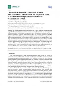
Figure 3. Horizontal and vertical Gray-coded binary patterns
a sensor board, which then relays the data to a host PC. Because each fiber is only 1mm in diameter, they minimize the physical presence of the sensor at the projection surface. Additionally, the fibers allow us to use a small electronics package placed in a convenient location regardless of screen geometry. The tip of each fiber lies just beneath the white front surface of the screen. This hides any visual evidence of the fiber, as seen in Figure 1, and provides a light diffuser that helps bounce light into the fiber even at very shallow projection angles. CALIBRATION PATTERNS
The structured light patterns we project are a series of Gray-coded binary patterns. Each pattern consists of blackand-white stripes that divide the projection area more finely with each successive step, as seen in Figure 3. When projected as a sequence, these images uniquely identify every pixel location. The optical sensors detect the presence or absence of projected light at each step and generate bit sequences that, when decoded, yield the x and y pixel coordinates corresponding to each sensor location. Gray-coded binary patterns have frequently been used in range-finding systems [Sal04] due to their robust spatial encoding properties and short minimum-sequence lengths [Tro95]. Unlike traditional binary division, the stripe boundaries in Gray-code patterns never occur at the same location. This prevents the catastrophic failures that would otherwise occur if a sensor were to straddle a division boundary. In fact, Gray-code patterns limit the error
resulting from boundary events to +/- 1 pixel. Gray-codes also have a O(log2(n)) relationship between the necessary number of patterns and the number of pixels, n. Every pixel in an XGA resolution projector (1024x768) can be uniquely identified with only 20 binary patterns, scaling nicely for future technologies with vastly higher resolutions (e.g., only 60 binary images are necessary to resolve the entire continental United States to millimeter accuracy). These patterns also allow calibration quality to degrade very gracefully under defocused conditions, since only the least significant bits of the calibration patterns are affected. This is an important characteristic that prevents failure when the target plane differs dramatically from the focusing plane. Since the number of encoding patterns is determined by the resolution of the projector, it is worth noting that the calibration time remains constant with respect to the number of optical sensors being located. Though only four are necessary for the current application, additional sensors provide redundancy that makes the system robust against sensor occlusion. Having more than the minimum number of sensors also permits best-fit solutions to be found yielding subpixel calibration accuracy. The current implementation thresholds optical readings to generate each bit sequence. The threshold value for each sensor is determined by averaging the readings from an initial black-screen level and an initial white-screen level. We have found this approach to be sufficient for a variety of indoor lighting conditions and projection distances. However, this can be improved upon by projecting each calibration pattern followed by its inverse and then differencing the two readings to determine the appropriate binary value. Differencing cancels out the effects of ambient lighting, but requires projecting twice as many patterns.
APPLICAT IONS
Automatic ally calibrating projectors have the potential to substantial Figure 4. From left to right: 8-sensor serial board, 4ly improve sensor USB board, 1-sensor RF wireless board. the quality of service and ease of configurati on of many existing projection systems. Projected images can be reliably, quickly, and accurately Figure 5. Top: Shader Lamps demo of decorating aligned to physical objects. Bottom: multi-projector stitching registratio n points at the push of a button, eliminating labor costs and the hassles of manual calibration. This loosens the physical constraints on the projector pose, permitting the shallow projection angles desired for front-projection installations.
Once the corner locations of the target surface have been discovered, a homography matrix can be computed to warp the source image to fit onto the projection surface. If the projector is flipped upside down, rotated, or even if the optical path is folded with mirrors, the homography will automatically flip and rotate the image to maintain proper orientation with the target surface [Wei99].
A wireless version of our optical sensors, shown in Figure 4, allows the projection screen to be completely untethered. As a result, light, hangable, bright, high-resolution displays can be made from simple pieces of stretched canvas. A single projector can also be calibrated onto multiple small screens simultaneously, thereby simulating several “picture-frame”-like displays haphazardly scattered on a bookshelf, mantle, or desk. Projectors with pan-tilt-zoom capabilities can locate target displays and zoom in to increase pixel density. Basic environment geometry can also be captured by temporarily placing calibration screens on desks, floors, and walls for multi-surface projection applications such as [Pin01].
Using a 3D programming environment such as OpenGL or DirectX, we can achieve real-time image warping on lowcost commodity hardware. It is worth noting that the computational resources necessary to perform this warping operation are similar to that of digital keystone correction, a feature already available in most modern projectors. We also have a software implementation that warps the active Microsoft Windows desktop, providing a fully functional calibrated projected computer display.
Retail-environment applications are an emerging area for experimental use of projection technology to dynamically highlight products, decorate physical display hardware, and dynamically present co-located product information. Our calibration technique makes it practical to deploy these otherwise “one-off” design explorations en masse by eliminating the need to have skilled labor on-site to maintain the installation. Recalibration can occur at the push of a button at the beginning of each business day.
USING THE HOMOGRAPHY
Shader Lamps [Ras01] is a method for using projected light
to decorate ordinary physical objects. Surface textures, illusion of movement, and different lighting conditions can all be simulated with projected light. However, these systems require extremely accurate calibrations to maintain the illusion. This is achieved through a tedious manual process lasting 15-20 minutes and must be entirely redone if either the model or projector is moved or adjusted even slightly. We have reconstructed a demo from the Shader Lamps work using our automatic calibration system, shown in Figure 5. Within 3 seconds, the gray model car is given a new paint job, a sunroof, and hubcaps. Eight optical fibers are embedded at key registration points around the model, connected to an 8-sensor board shown in Figure 4. These registration points are used to discover the projector pose with respect to the physical model, given knowledge of the model geometry and sensor locations. By making this illusion easier to achieve, the realm of appearance customization and dynamically decorative objects takes a step closer to becoming a practical reality. Setting up multi-projector systems is also substantially simplified through the use of embedded optical sensors. Projector stitching is a simple extension of single-display calibration. In Figure 5, two projectors are stitched together using a board containing six sensors (one in each corner and a shared pair at the midpoints of the top and bottom edges). Each projector is calibrated sequentially, warped, and then blended. This stitching technique easily scales to larger numbers of projectors and can also be applied to non-planar surfaces such as a planetarium. Additionally, we have found that the accuracy of our system is sufficient for calibrating multiple projectors onto the same display area without causing any noticeable multiimage artifacts. Projector overlap can be used for increasing image intensity, stereoscopic projection, and reducing the visual impact of shadows resulting from occlusion (useful when projecting onto interactive touch surfaces). DISCUSSION AND FUTURE WORK
Our current prototype successfully calibrates with projection angles less than two degrees from the target surface plane. Often, the expansion of the projection frustum is sufficient for the calibration to succeed even when the target surface is parallel to the optical axis of the projector. However, because the image warping is done digitally, pixels are sacrificed for the sake of proper alignment. This has the disadvantage of reducing image quality as the magnitude of warping increases. This degradation mostly impacts the readability of small text and the appearance of fine lines, but larger text and images maintain a reasonable appearance even under substantial warping. However, extreme calibration angles will result in unusable images. Image filtering does help in the appearance of down-sampled video, but we are ultimately
subject to the physical limitations of the projector. This calibration technique can be combined with higher resolution projectors or pan-tilt-zoom optics to help offset this limitation. Unlike vision-based techniques, our system does require an augmented projection surface. Though the total cost of instrumentation, in volume, may be as little as $5 per screen, the details of some applications may make advanced augmentation of the projection surfaces impractical. However, many of these can be accommodated by temporarily placing wireless "sticker" tags on the surfaces for calibration. Our fastest implementation is currently capable of calibrating an XGA resolution projector with a 60Hz refresh rate in 367 milliseconds. There are several simple techniques for increasing the speed of calibration including refresh synchronization, RGB separation, and n-ary Graycode patterns. Combined, these techniques may yield an order of magnitude in speed improvement. However, our current work is focused on Digital Light Processing (DLP) technology, which is capable of projecting 9700 binary images per second and can operate in the infrared spectrum. We hope to eventually achieve rates fast enough to calibrate onto moving or dynamic surfaces. This ability will unlock several novel interaction techniques, concepts, and new applications in HCI and computer graphics. REFERENCES [Pin01] Pinhanez, C. “The Everywhere Displays Projector: A Device to Create Ubiquitous Graphical Interfaces.” Proceedings of Ubiquitous Computing 2001. [Ras98] Ramesh Raskar, Greg Welch, Matthew Cutts, Adam Lake, Lev Stesin, and Henry Fuchs. “The office of the future: A unified approach to image-based modeling and spatially immersive displays.” In Proceedings of SIGGRAPH '98. ACM Press, 1998. [Ras01a] R. Raskar, G. Welch, and K.-L. Low. “Shader Lamps: Animating real objects with image-based illumination.” In Proceedings of Eurographics Workshop on Rendering, 2001. [Ras01b] Raskar, R., Beardsley, P.A., "A Self-Correcting Projector", IEEE Computer Society Conference on Computer Vision and Pattern Recognition (CVPR), December 2001. [Suk01] R. Sukthankar, R. Stockton, and M. Mullin., “Smarter presentations: Exploiting homography in camera-projector systems,” In Proceedings of International Conference on Computer Vision, 2001. [Tro95] M. Trobina, “Error model of a code-light range sensor,” Tech report, Communication Technology Laboratory, ETH Zentrum, Zurich, 1995. [Sal04] J. Salvi, J. Pagés, J. Batlle. Pattern Codification Strategies in Structured Light Systems. Pattern Recognition 37(4), pp. 827-849, April 2004. [Wei99] Eric W. Weisstein. "Homography." From MathWorld--A Wolfram Web Resource. http://mathworld.wolfram.com/ Homography.html.