Synthesis of Concurrent Asynchronous State Machines Using Extended Multi-Burst Graph Specification Duarte Lopes de Oliveira1 Marius Strum2 Fabio Durante Pereira Alves1 Jéfferson Perez R. Costa3 Wang Jiang Chau2
1
Divisão de Engenharia Eletrônica do Instituto Tecnológico de Aeronáutica – IEEA – ITA
[email protected] [email protected] Praça Marechal Eduardo Gomes, 50 – CEP 12228-900 – São José dos Campos – SP – Brazil 2 Laboratório de Microeletrônica da Escola Politécnica da USP
[email protected] [email protected] Av. Prof. Luciano Gualberto, Trav 3, 158 – CEP 05508-900 – São Paulo – SP – Brazil 3 Departamento de Engenharia de Computação e Telecomunicações da Universidade Católica de Santos
[email protected] Av. Conselheiro Nébias, 300 – CEP 11015-002 – Santos – SP – Brazil
Abstract Extended Huffman machines implemented with basic gates present an optimum latency time and only use the standard-cell technology. Due to the limitations of the existent synthesis methods for asynchronous controllers, these machines are only used for applications where there is limited concurrence between inputs and outputs (I/O concurrence). In these cases, the interaction with the environment happens in the generalized fundamental mode (GFM). This limitation degrades the performance. In this paper we propose an extension of the multi-burst graph specification (MBG) called of extended multi-burst graph (XMBG) that describes asynchronous finite state machines that present a limited amount of I/O concurrence. We also propose a method that synthesizes such controllers as hazard-free extended Huffman machines. Our results show that the XMBG specification was able to describe a few known benchmarks used in interface controller. The experimental results show that there is an area and a latency time improvement for our solution compared to the solutions coming from the Petrify synthesis tool when synthesizing the SoP+latchC architecture. Both solutions require only a standard cell library for their physical implementation.
1 - INTRODUCTION The modern digital systems complexity and the necessity of performance improvement has been driven considerable interest in asynchronous design [1]. One promising application area is in Heterogeneous Systems (synchronous and asynchronous mixed modules) [7,8,9]. The behavior of such circuits can be represented as a Signal Transition Graph (STG) [4]. STG is a Petri-net description. Signal transitions describe events. The strength of STG is to describe concurrence between inputs and outputs (I/O concurrence) that occur in heterogeneous systems. However, the larger the number of signals or if there are decisions involving level sensitive signals – (LSS signals) the description becomes very confusing.
Furthermore, this type of description may explode in the size [2,3,10]. Petrify1 [10] is a known synthesis tool that starts from an STG and implements timed controllers2 using two types of architecture: sum-of-products + latch C (SoP+latchC) or complex gates [10]. The resulting circuits obey the bounded gate and wire delay model and operate according to the generalized fundamental mode (GFM). Complex gates present optimal area and latency time at the expense of a full custom design. SoP+latchC present lower latency time and larger area but require only a standard cell solution [5,6,10]. On the other hand, burst mode specification (BM, XBM) solves the problems related to the STG description but is very limited to describe I/O concurrency [5,6]. It is the natural description of finite state machines3. One type of burst mode specification is the multi-burst graph (MBG). It accepts all signals types of the XBM specification and introduces burst operators that allow the description a limited amount of I/O concurrency. There are three types of operators: input burst OR, transition concurrence (CO) and transition sequence (SEQ) [5,6]. We propose an extended version of the MBG (XMBG) that further increases the I/O concurrency allowing the combination of the CO and the SEQ operators. In this work we explain the XMBG specification and show that it may be used to synthesize hazard-free asynchronous controllers as an extended Huffman machine composed exclusively on basic gates [1,7,8]. Such a solution present nice area and latency time properties when compared to the SOP+latchC solution 1
This tool also implements SI controllers. These controllers operate in the I/O mode and they obey the model bounded gate and wire delay. 3 The tools 3D and Minimalist starts this of specification [7,8,9]. 2
from Petrify while keeping the nice properties of a standard cell design methodology. This paper is structured as follows: section 2 presents formally the XMBG specification; section 3 describes concisely the synthesis procedure; section 4 shows our experimental results. Finally section 5 brings the conclusions and future works.
2- XMBG SPECIFICATION The burst-mode specification (BM) belongs to the class of specifications that allow multiple-input change. It is represented by a graph in which nodes represent stable states while arcs represent state transitions [9]. Yun [7,8] proposed the extended burst-mode specification (XBM) adding two features: directed don’t care signals (which allow an input signal to change concurrently with an output signal) and level sensitive signals (LSS) with non-monotonic behavior, that may be used with conditionals signals. In order to describe a limited concurrent behavior between input signals and output signals, Oliveira [5], created a new specification called Multi-Burst Graph specification, MBG as an expansion of the XBM specification. Like in the XBM, a MBG represents a state graph in which each node represents a state and each arc represents a transition. Each transition in the MBG can be activated by: 1) an input burst; or 2) a burst expression. We introduce the input burst OR4, the transition concurrence (CO) and the transition sequence (SEQ) operators. The use of burst expressions based on these operators increase the possibility to describe I/O concurrence.
2.1- I/O Concurrence behavior using burst operators Situation 1: Consider the timing diagram shown in figure 2a. a 0
b
0
1a
c
1
1
c+ / y+
y 1b
d
0
a+ b+c+ / x+ y+
a+ b+ / x+
x
2
2
a- d+ / x- y-
2
a+ b+ / x+ CO b+ c+ / y+ a- d+ / x- y-
a-d+ /x-y-
(a)
(b)
(c)
(d)
Figure 2 - Specification types: a) timing diagram; b) XBM_1; c) XBM_2; d) MBG (CO operator).
This behavior can be naturally captured by a STG. However the same behavior can be captured in the form of bursts. This behavior can be described in XBM defining two sequential state transitions activated by the input bursts (a+b+ / x+) and (c+/y+) (figure 2b). This solution creates a dependency between this pair of bursts that does not exist in the application. Another solution would be to define a unique state transition activated by the burst (a+b+c+/x+y+) (figure 2c). This solution creates a dependency between a+ and y+ and between c+ and x+ 4
The OR operator don’t part in this work.
that also does not exist in the application. These dependencies preserve the inputÆoutput sequence, but increase the latency time of the transition. A more efficient solution consists in describing this behavior through two concurrent but independent bursts (a+ b+/ x+) CO (b+ c+/ y+) (exactly as the timing diagram). This description creates a degree of concurrency between inputs and outputs (figure 2d). The state transition 0Æ1 of the figure 2d is of the type TCO. Situation 2: Consider the timing diagram shown in figure 3a. a 0
0
b
a+b+/ x+
x
> 1
1a
c
c+/ y+
y 1b
d
2
a+b+/ x+ c+/ y+ a- d+/ x- y-
2
a-d+/x-y-
(a) (b) (c) Figure 3 - Specification types: a) timing diagram; b) XBM; c) MBG (SEQ operator Æ symbol >). This behavior can be naturally captured by a STG. However the same behavior can be captured in the form of bursts. This behavior may be described in XBM defining two sequential state transitions activated by the inputs bursts (a+b+/ x+) and (c+/ y+) (figure 3b). Let’s suppose that the input burst c+ is activated immediately after the activation of the output signal x+, but not obeying the GFM. If the tools 3D and Minimalist synthesize this behavior in the architecture of Huffman, elements of delay should be inserted in the line of the signal c, to satisfy the GFM. This procedure however degrades the performance and reliability of the controller. A more efficient solution consists of describing this behavior through two sequential bursts but activated immediately (a+ b+/ x+) SEQ (c+/ y+) (exactly as the timing diagram). This description creates a limited degree of concurrency between an input c and the output x (figure 3c), therefore, eliminates the need to satisfy the GFM. The state transition 0Æ1 of the figure 3c is of the type TSEQ.
2.2- I/O Concurrence behavior using combination of burst operators An extended burst expression is characterized by inputs burst related by the SEQ and CO operators. Let T1, T2 and T3 be three state transitions. There are two valid options to combine operators: 1. 2.
(T1 CO T2) SEQ T3 (T1 SEQ T2) CO T3
The timing diagram shown in figure 4a illustrates option 2.
a 0
x b
0
a+ c+ / x+ z+
1a
1a
c
0
a+ b*/ x+ b+ c+ / z+ y+
b+ / y+
y 1b
d
2
a-d+ /x-y-
1b
2
1
0
Ao+Ri+ /L+
a+/ x+ > b+/y+ CO c+ / z+
3
a- d+ / x- y-
1
Ao-Ri- / L+
D-/ (RoCO L->Ai-)
2
a-d+ /x-y-
D+/ (Ro+ CO L->Ai+)
2
z
(a)
(b)
(c)
(d)
Figure 4 - Specification types: a) timing diagram; b) XBM_1; c) XBM_2; d) XMBG (SEQ/CO operators).
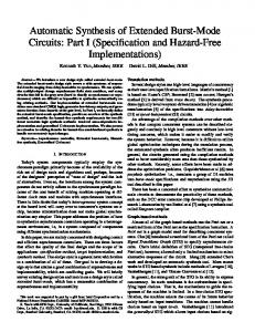
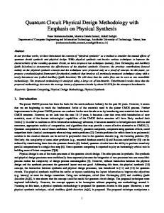
This behavior can be naturally captured by a STG. The same behavior can be captured in the form of bursts. Figure 4b shows this behavior described in XBM. Two sequential state transitions are activated by the inputs bursts (a+c+ / x+ z+) and (b+/y+). This solution may violate the fundamental operation mode in fast environments, because b+ can only be activated after the output burst x+ and z+ is stable. It also creates the inexistent dependence between the signals c+ and z+. Another solution for fast environments is shown in figure 4c. The signal b* (directed don't-care) eliminates the fundamental mode violation problem, but creates two inexistent dependences: 1) c+ can only be activated after the x+ activation; 2) y+ will only be activated after the c+ and b+ activations. A more efficient solution shown in figure 4d consists in describing this behavior exactly as is in the timing diagram, through two concurrent but independent bursts (a+/ x+ SEQ b+/ y+) CO (c+/ z+). The state transition of the figure 4d is of the type TS-C. The FIFO interface controller benchmark (see figure 5 – FIFO cell) has 3 inputs (Ao,Ri,D) and 3 outputs (Ai,Ro,L) [4,10]. Figure 6 shows the STG description of the FIFO controller. Figure 7 shows how we described the same behavior in XMBG using the CO/SEQ burst expression. The state transitions 0Æ1 and 2Æ3 are of the type TS-C depend on the CO/SEQ burst expressions. The state transitions 1Æ2 and 3Æ0 are of the type TS (simple transition – without operator). Ri
Ro
FIFO CELL
Ai
A0
L D REGISTER
DATA
DATA
Ri-
D+
RoL+
L-
Ai+
Ao-
2.3 – Restrictions in XMBG In order to guarantee the implementability of an XMBG specification, it must be obey five restrictions [5,6]: 1. Signal polarity; 2. State conflict condition; 3. Distinguishability condition; 4. Unique entry condition; 5. Valid burst expression. Conditions 1 and 2 are inherited from the MBG description while conditions 3, 4 and 5 are extended from the MBG [6].
3 – SYNTHESIS METHODOLOGY The synthesis methodology performs the following tasks: 1. Behavioral capture using the extended multi-burst graph (XMBG) specification. 2. Transformation of the XMBG into a table of signals transition cubes, STC [5,6] . 3. State variable insertion: compatible classes minimization and assignment (adapted algorithms ─ [8,9]). 4. Logic minimization for each non-input signal of the extended Huffman machine [6].
3.1 SEQ-CO transition cover All of the types of state transition of XMBG are functional hazard-free [6]. Each type is cover by a signals transition cube (STC) and cells are reserved to allow hazard-free logic minimization in the EHM architecture using basic gates. Figure 8 shows the corresponding state flow table of the TS-C transition of the figure 4d (0Æ1). The cells of the table with the content R are reserved for the cover. The STC cube is formed as: cube A is abcdxyz=2220000; cube B is abcdxyz=1220222; cube C is abcdxyz=1220122; cube D is abcdxyz=2210222 (where 2 is don’t-care). abc
Figure 5 – Block diagram of the FIFO cell.
Ro+
Figure 7 − FIFO interface controller in XMBG.
xyz
Ri+ L+
D-
000 010 000 ooo 0
100 100
101 101
010
R
R
R
R R
110
110
R
R
111
R
100
110
100
111
R
101
R
R
101 101
111
111
R
R
R
111
R R
011
R R
R
R
R
R
R
101
R
001
001
L-
Ai-
Ao+
Figure 6 – FIFO interface controller in STG
d=0 110 R
111
011
001 001 R
1
Figure 8 – State Flow Table: covering of the transition of the type TS-C.
3.2 Logic hazard-free conditions The following lemmas (without proof) present the necessary and sufficient conditions to ensure that the AND-OR implementation (extended Huffman machine) of f has no logic hazards for the given specified multi-burst transitions types {TS, TSEQ, TCO, TS-C}5. Cov is a cover of f implemented in AND-OR logic (EHM architecture).
SIGNAL
CONVERTA
The exact logic minimization task can be performed using different algorithms like: Quine-McCluskey [9] or even Karnaugh maps provided that the selected prime implicants for the Cov cover satisfy the lemmas. The figure 9 show the hazard-free logic circuit of the FIFO interface controller synthesized by our method. Ao Ri
D
R0 L
Ai
Figure 9 – Logic Circuit: FIFO controller
4 – RESULTS and DISCUSSION Table 1 shows the 5 known benchmarks used in our experimental study. All of them present at least one transition based on a CO/SEQ expression. Petrify produced SoP+latchC solutions while our method produced only SoP extended Huffman machines. All of them operate in the GFM and obey the bounded gate and wire delay model. There are two results columns for each case: area measured as the # of transistors and latency time. It can be seen that our method leads to a smaller area in 3 (out of 5) benchmarks6 and to a smaller latency time7 in 4 cases. It can be also seen that the overall area reduction for our method is 14% and 16% for latency time.
5
Logic hazard for the state transitions types TS TSEQ and TCO were already discussed in [5,6]. 6 The latchC area was estimated as twice the area of a NOT gate. 7 Based on the IMEC-96 0.7um standard cell library.
OUR METHOD Number Time of of Latency (ns ) Transistors
2/3
80
1,41
86
1,06
4/1
18
1,00
20
0,93
FIFO
3/3
68
1,41
42
0,93
MENG7
2/2
16
0,48
14
0,80
36
1,00
18
0,69
218
5,3
180
4,41
EBERGEN -C
PAR TOTAL
Lemma 3.1: If f has a 1Æ1 transition in cube (STC-SC[A,B,C,D]), then the implementation is free of logic hazards if and only if the cubes A, B, C and (D) are within some cube of the Cov cover. The conditions for the 0Æ1 and 1Æ0 cases are symmetric (see [6,9]) Lemma 3.2: If f has a 0Æ1 transition in cube (STC-SC[A,B,C,D]), then the implementation is free of logic hazards if and only if the cubes f(B)=1, f(C)=1 and (f(D)=1) are within some cube of the Cov cover, and if there is a cube E of Cov that intersects either cube B or C or D, then E should cover the final state of the transition.
PETRIFY Number Time of of Latency (ns ) Transistors
3/3
---
Table 1: Benchmarks
5 – CONCLUSION In this paper we presented XMBG, an extension of the MBG specification that allows to describe asynchronous finite state machines that present a limited degree of I/O concurrence. A synthesis method was also proposed that targets the extended Huffman machines exclusively composed of basic gates (standard cells). Our results were compared to those produced by the Petrify synthesis tool targeting the SoP+latchC architecture. Both solutions require only standard cell libraries. We showed that in many cases we obtained better area and latency time results while keeping the benefits of the standard cell design methodology. We are now working on a CAD tool that has been implemented will allow the automation of the design methodology in order to synthesize large examples.
References [1] RENAUDIN, M. Asynchronous circuits and systems: a promising design alternative. Microelectronic Engineering, vol.54, pp.133-149, 2000. [2] YAKOVLEV, A. V. On limitations and extensions of STG model for designing asynchronous control circuits. Proc. Int. Conf. Computer design, pp.396-400, October 1992. [3] VANBEKBERGEN, P. et al. A generalized signal transition graph model for specification of complex interfaces. European Design and Test Conference, EDAC, pp.378-384, March 1994. [4] CHU, T. -A. Synthesis of self-timed VLSI circuits from graph-theoretic specifications. PhD thesis, Dept. of EECS, MIT, June, 1987. [5] OLIVEIRA, D. L. Miriã: Uma Ferramenta para Síntese de Controladores Assíncronos Multi-rajada. Tese de Doutorado, EPUSP, 2004. [6] OLIVEIRA, D. L. Synthesis Extended Multi-Burst Controllers using XMBG, Technical Report, Number. 2/2005 - Instituto Tecnológico de Aeronáutica - Brazil. [7] YUN, K. Y.; DILL, D. L. Automatic synthesis of extended burst-mode circuits: part I (specification and hazard-free implementation). IEEE Trans. on CAD of Integrated of Circuit and Systems, vol. 18:2, pp.101-117, February 1999. [8] YUN, K. Y.; DILL, D. L. Automatic synthesis of extended burst-mode circuits: part II (automatic synthesis). IEEE Trans. on CAD of Integrated of Circuit and Systems, vol. 18:2, pp.118-32, February 1999. [9] NOWICK, S. M., Automatic Synthesis of Burst-Mode Asynchronous Controllers. PhD thesis, Stanford University, 1993. [10] CORTADELLA, J. et al. Petrify: a tool for manipulating concurrent specifications and synthesis of asynchronous controllers. IEICE Trans. on Information and Systems, E80-D(3), pp.315-325, March 1999.