Available online at www.sciencedirect.com
ScienceDirect Procedia CIRP 29 (2015) 62 – 67
The 22nd CIRP conference on Life Cycle Engineering
Automatic Variant Configuration and Generation of Simulation Models for Comparison of Plant and Machinery Variants Adrian Neyrincka*, Armin Lechlera, Alexander Verla a ISW University of Stuttgart, Seidenstr. 36, 70174 Stuttgart, Germany * Corresponding author. Tel.: +49-711-685-84530; fax: +49-711-685-74530. E-mail address:
[email protected]
Abstract Manufacturers of machines and plants are faced with the challenge to quickly find, compare and evaluate solutions for their customers during the tendering phase. Besides acquisition costs, figures about life cycle costs and energy efficiency are claimed by sustainability-aware customers when making a choice between different possible solution variants. In this paper an approach for automatic variant compilation and simulation model generation, based on mechatronic modules, is introduced. The results, validated using an example application of a modular transfer system, show that using the proposed method can significantly speed up the process of finding the appropriate module configuration based on reliable simulation models even for non-simulation-experts. © © 2015 2015 The The Authors. Authors. Published Published by by Elsevier Elsevier B.V. B.V. This is an open access article under the CC BY-NC-ND license Peer-review under responsibility of the International Scientific Committee of the Conference “22nd CIRP conference on Life Cycle (http://creativecommons.org/licenses/by-nc-nd/4.0/). Engineering. Peer-review under responsibility of the scientific committee of The 22nd CIRP conference on Life Cycle Engineering Keywords: Variant Management; Simulation; Mechatronic Engineering; Life Cycle Costs
1. Introduction Manufacturers of machines and plants are faced with the challenge to find, compare and evaluate solutions for their customers during the tendering phase. Besides the acquisition costs the total investment costs over the complete life cycle (Total Cost of Ownership TCO) and the energy efficiency play more and more a major role. In addition, the European Union public procurement directives meanwhile require information on energy consumption of technical devices and equipment or a minimized life cycle cost analysis [1]. This paper presents research results from the project „Simulation-based consideration of variants during the conception of machines and plants – SimVar” funded by the Ministry of Economy and Finance Baden-Wuerttemberg, in which methods and tools for the automatic generation of variants and the simulation-based comparison of the variants have been developed. 2. Requirements and related work For the customer-specific production of machine variants it is necessary to handle and cope with the resulting multitude of
variants. A pure price comparison of the needed components is counterproductive because always the interplay in the overall system is what counts in the application. Consequently, a general statement about which components are most suitable for a particular application and provide the best priceperformance ratio (e.g. a drive system – electric/pneumatic) is not possible. For the design of simulations during the tendering phase it must be ensured that also users without expert knowledge of simulations can compare variants. Thus, the challenges arise to automatically generate the simulation models, to create the control of the simulated facility and to execute a simulation run and the evaluation automatically. With modular mechatronic engineering systems, today it is possible to create individual solutions based on proven-in-use components used in a company, like for example linear axes, drives, transmissions, etc. [2, 3]. Thereby, the objective to make the engineering faster and less prone to errors is pursued by the systematic reuse of components [4, 5]. In the modular system, fragments of the production data and documentation of each engineering discipline, e.g. bills of materials, wiring diagrams and PLC programs as well as CAD data, are stored for each component. These are automatically
2212-8271 © 2015 The Authors. Published by Elsevier B.V. This is an open access article under the CC BY-NC-ND license (http://creativecommons.org/licenses/by-nc-nd/4.0/). Peer-review under responsibility of the scientific committee of The 22nd CIRP conference on Life Cycle Engineering doi:10.1016/j.procir.2015.02.069
63
Adrian Neyrinck et al. / Procedia CIRP 29 (2015) 62 – 67
compiled into the full data and documents according to the previously defined rules during the projecting phase [6]. Simulation models can also be added to the components so that a simulation can be generated for the projected solution [7], for example, kinematic and dynamic simulations with associated 3D simulation models. One such approach uses company-neutral simplified and parameterizable basic components (pneumatic cylinders, motors, transmissions, etc.) that can be combined and allow for the analysis of alternative solutions [8]. However, modular systems with concrete components are not apt for the concept exploration phase because it has not yet been defined with which components or with which solution principle the later solution will be realized. In order to find a conception within the tendering phase it is necessary to determine the features „from gross to subtle”. If, for example, a linear motion is to be generated, it should not happen that one of the suitable components (cylinder, linear motor) is taken over immediately from the modular system into the project, but the linear motion should be instead stored as a problem description. Therefore, modular mechatronic systems that allow for a problem description and not a solution description are required. Consequently, the user must not model with basic components like pneumatic cylinders, motors and transmissions, but he should describe the task to be realized by means of a suitable specification technique. Based on this problem description such a tool can propose component combinations as adequate solution variants and compare them. In the field of mechatronic modular engineering, there are still no approaches for problem description libraries. For the reconfiguration of machines and the planning of logistics facilities, methods for a skill-based selection of the components to be implemented were analyzed with knowledge-based systems or ontologies [9-11]. These methods that have their origin in the Semantic Web area and served in the present research as basis for an adaption to use for problem description libraries in the area of mechatronic modular engineering. For the automatic generation of simulation models from mechatronic module systems various concepts and solutions exist [5, 12, 13]. In the project aquimo solutions have been developed in which the XML- and VRML-based descriptions of the simulation models are generated fully automatic [8]. Here the entire model description is stored in the modules. Since this affects the performance during generation considerably, methods are examined in the SimVar project that allow for a more efficient model generation with referenced models.
Module Repository Standardmodules
Skills
Variantassistant
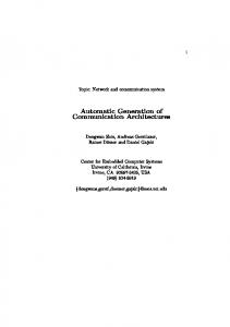
2.1. Requirements and Solution approaches for a Method to Generate and Simulate Variants In order to support the users of the method usefully, the following requirements have been identified and related solutions determined (in brackets): x The input of requirements and not solutions has to be possible. (Usage of problem description libraries) x The effort for variant generation must be kept low. (Automatic generation of variants with formalized knowledge) x The number of variants to be simulated must be reduced by adequate criteria. (Limitation of the acquisition costs, restriction to certain component producers and more) x The effort for simulation must be low. (Usage of premade simulation model fragments) x For the creation of the simulation model, expertise must not be necessary. (Usage of premade simulation fragments, generation of models) x It should be possible to generate the model control without programming skills. (Table-based workflow description as sequence description, generation of control prototypes) 3. Research approach 3.1. Method for the Generation and Simulation of Variants In this contribution a method is proposed that extends the available standard components of modular mechatronic engineering systems by problem description. These contain modules for the abstract description of the desired capabilities (skills) of the machines and plants independent of standard components. These capabilities are assigned to each available standard component. One example: A belt conveyor module is assigned the capability “convey” from the problem description library. If the conveyor has lateral guides the capability “guide” is also assigned to it. In order to generate variants of a machine or plant, first the problem description is compiled using the problem description library. This is done in a problem description configurator with graphical support and wizards in a variant assistant (Figure 1). Based on the abstract description of the capabilities the variant assistant generates automatically variants with concrete standard components by selecting those components from the modular system that contain the capabilities required in the abstract description.
Variant 1..n
Generate
Behaviour Model 3D Model M d l Control C t l Prototype
Fig. 1. Customer order workflow with the SimVar software tool
Inquiry Inqu In quiririryy 2 qu Inquiry1 Best Variant Simulation & Evaluation
Generate
Customer Offer Wi i Wiring Diagram Control software …
64
Adrian Neyrinck et al. / Procedia CIRP 29 (2015) 62 – 67
Since most of the time there are different suitable components for a required capability, more than one variant results during the automatic generation of a solution by means of a problem description. For selected variants a simulation model is generated automatically from model fragments of the individual components, so that a simulation run can provide information about the energy efficiency, cycle times etc. In the following chapters the different parts of the approach are described. 3.2. Skill-based problem description The approach is based on the object-oriented model element of the directed association. Fig. 2 shows the resulting class structure for mapping skills of the individual components. This structure uses only a generalization ("a concrete component is an abstract component"). The assignment of skills to the specific components takes place via the directed association "has". In addition, each skill can have none, one, or more constraints.
assistant offers the possibility in a path editor to store required skills, their constraints and geometric specifications for the problem description. For the description of non-geometrical problems the system editor is used. 3.3. Variant instantiation User inputs into the editors cause an instantiation and parameterization of the components in the problem description part of a project (Fig. 4). By means of a variant generator, the concrete standard modules, corresponding to the skills of the problem description, are instantiated. Subsequently, the parameters of the Modules are calculated from the constraint values of the problem description.
Project Root Node -
Problem Description -
Skill 1 -
has Abstract m Component n
Skill
has n
m
Constraint 1 Constraint Value
Constraint
Constraint n Skill n
Concrete Component
-
Variant 1 -
Fig. 2. Class structure of the skill model in the realized approach
Module 1 Parameter 1 Parameter n
Fig. 3 illustrates an example of how a deflection module of a chain conveyor can be described with the selected data model. Its associated skill is “deflect”. However, the module cannot deflect arbitrarily. Therefore, the skill "deflect" in this case, is subject to the constraint "deflection angle 90°".
Module n Variant n
Fig. 4. Instantiation and parameterization of Variants
3.4. Generation of Simulation Models
Skill: deflect
Constraint: deflection angle 90°
Fig. 3.Example of a skill/constraint model of a transfer system module
In order to create a problem description and to generate a variety of solutions, editors and generators are needed. These are contained in the variant assistant (Fig. 1). The variant
Simulation tools use different data formats to store their models and offer different import and programming interfaces. The simulation models consist of large model descriptions, e.g. an XML format for the behavioral description and a VRML description for the description of 3D geometries. If the formats are text-based or disclosed binary formats, they can be automatically generated by the rules of common modular mechatronic engineering systems. In the simplest case, the model description is text-based, for example, an XML format. In the case of text-based documents, generators are controlled by means of so-called body and fragment files. Body files contain the body of the text file to be created and refer to the fragments to be inserted by the means of control structures. Generation of the whole VRML or XML description containing every bit of geometry or behavior models have proven to take too much CPU and memory resources resulting in a slow generation process even with few machine modules. Therefore, a new description was specified where only references to models parameter values and interconnection information are generated. Thus, the full description is stored
Adrian Neyrinck et al. / Procedia CIRP 29 (2015) 62 – 67
in a separate repository and does not affect the generation process. The example of a 3D geometry description in the XML format specified in the course of the SimVar project (Fig. 5) is suitable to explain the principle. The LOOP statement serves as a control structure for the generator to insert all Visualization fragments of the discipline objects (“dos”) in the correct place for all modules contained in the mechatronic project. (*{LOOP:dos('ecf_Architecture.ecf_VisualizationObject')} *)(*{Content}*)(*{END_LOOP}*) Fig. 5. Body file for the generation of 3D geometry files
Included in special bracketing syntax are generating commands for inserting parameter values: #{Parametername} and strings to be evaluated by the rule of the modular mechatronic system: engine (*{=Formula}*). (*{=mc.$transX}*),(*{=mc.$transY}*),(*{=mc.$transZ}*) (*{=mc.$rotX}*),(*{=mc.$rotY}*), (*{=mc.$rotZ}*) (*{=mc.$angle}*)
Fig. 6. Machine object fragment for the generation of 3D geometry files
For the simulation of energy consumption, the previously modeled simulation model of each energy-consuming module in the repository has to include an energy-consumption model. For electric drives, e.g. synchronous and asynchronous motors, a detailed motor model is used that is parametrized using the motors data sheet. For pneumatic actuators, the consumption of compressed air is calculated according to the actual performed movements and is charged with an air-compressor cost constant.
the description of sequences and logic relations between sensors and actors as well as the description of operator actions and sequences, e.g. loading and unloading of Parts at a transfer system. 4. Implementation & Evaluation 4.1. Example Scenario & Software Demonstrator The following scenario was worked out together with experienced employees from the technical sales department of the project partner Schnaithmann GmbH as an example application for validating the method: The customer of a supplier for transfer systems will acquire two machine tools that need to be linked together by a transfer system. He has a certain installation surface and so he would like to get a proposal from the supplier for the appropriate installation and a transfer system. Two different types of work pieces will be machined in both machines one after the other. Therefore, in front of each machine the type of work piece has to be recorded by a sensor system. The parts are to be loaded and unloaded at manual places. Further criteria are: work piece geometries, work piece masses, work piece sensitivity, environmental conditions (oil, chippings). For the creation of the necessary mechatronic modular system as well as for the problem description configurator, the editors and generators, “EPLAN Engineering Center” has been used and extended [6]. For the simulation the simulation suite “ISG-virtuos” has been used and enhanced [15]. The skill model has been implemented using a relational database which was connected to the Engineering Center. By now it contains nine Skills, twelve constraints and 21 Components. Fig. 7 shows the variant assistant; Fig. 8 shows the path editor; Fig. 9 shows the editor for the table based sequence description; Fig. 10 shows an automatically generated state graph running in the simulation system; Fig. 11 shows an automatically generated 3D Simulation model; Fig. 12 shows simulation results (energy consumption) of the variants of the example application; Fig. 13 shows an automatically generated customer offer with variant comparison.
3.5. Model Control For the implementation of the simulation sequences in the future plant the module-spanning control functionalities not contained in the modules control fragments have to be reproduced. For this purpose a description form needs to be found that enables the specification of the control functions without programming skills. Approaches for this have already been proposed in the aquimo project. A simulation-integrated state graph model based on graphically configured Gantt and function block diagrams is generated automatically. A survey of designated SimVar users showed that the functions of the plants in practice rarely are generated with Gantt and function block diagrams but in tabular form as textual sequence description with involved sensor and actuator signals as well as operation times. Thus a method has been developed for the SimVar tool which allows such a description and also generates simulation-model-integrated state graphs. The method allows
Fig. 7. Variant assistant of the SimVar-tool
65
Adrian Neyrinck et al. / Procedia CIRP 29 (2015) 62 – 67
E nergy consumption [W s]
66
Fig. 8. Path editor of the SimVar-tool
Variants 1 to 6 Fig. 12. simulation results (energy consumption) of the variants of the example application
Fig. 9. Editor for the table based sequence description
Fig. 10. Automatically generated state graph
Fig. 13. Automatically generated customer offer with variant comparison
4.2. Evaluation
Fig. 11. Automatically generated 3D Simulation model
The software demonstrator has been evaluated by the technical sales department of the project partner. The problem description, control sequence configuration, simulation generation, simulation run and customer offer generation have been finished after less than twenty minutes.
5. Conclusion In the sales and design phase of machines and systems it has been hardly possible to compare different variants based on
Adrian Neyrinck et al. / Procedia CIRP 29 (2015) 62 – 67
simulations with each other. Engineers in sales areas shall neither apply the necessary technical expertise for the creation of simulations and control prototypes, nor the expenses required for conventional variant elaboration and development of simulation models. In the research project SimVar, suitable approaches for the three areas creation of variants, generation of control prototypes and generation of simulation models that allow the sales engineers an effort-poor and simple comparison of alternatives. For the variant creation a concept has been created, which, through the use of a formal description of component capabilities, allows an automatic variant formation. For this purpose, a data model for skills and associated constraints has been created and stored in a database structure with userfriendly input user interface. Furthermore, a variant assistant was created for the component neutral skill-based problem description with the necessary rules for instantiation and configuration of variants and their real components in the SimVar tool. Creating control prototypes is necessary to provide the plant variants with control data according to their applicationspecific control logic and to process sensor data during the simulation as well as to specify operator actions. Hereby the Sales Engineer should not require knowledge of a PLC or CNC programmer; but nevertheless should be able to specify processes and sensor / actuator connections. To find a suitable description and a suitable execution environment for this purpose, different options were considered. The interview of the project partner Schnaithmann GmbH showed that the internal form of documentation for processes, a table-based process description, is a useful means of description. For the adaptation of such a table-based process description, a concept was created and integrated into the variant assistant of the SimVar tool. The concept implies that from the table-based process description, a state graph is generated, which enables an execution during the simulation within the same solver. The comprehensive framework for the automatic generation of the state graph has also been integrated into the variant wizard. To enable the simulation of production for sales engineers, a suitable library mechanism for storage and management of 3D geometry, behavioral, and life cycle costing models was created, first, on the other hand, a new interface for automatic model generation was designed and implemented. In addition, the necessary mechatronic modules and rule sets for automatic generation have been created. Finally, the concepts in the described the three areas were implemented in the software demonstrator "SimVar tool", which extends existing software systems of the project partners: on the one hand the EPLAN Engineering Center was expanded and on the other hand the simulation environment ISG-virtuos was extended with new features. To evaluate the concepts and the resulting demonstrator, a criteria catalog was created by the company Schnaithmann. The prototype was evaluated by both experienced sales engineers, as well as modular mechatronic engineers using the criteria catalog. They come to the overall rating that the use of the tool is very
67
promising and that they envision a wider use in application practice. According to them, on the one hand the effort for the rules and simulation models creation has to be reduced further, on the other hand they see a clear competitive advantage. Acknowledgements The research leading to these results was conducted at the Institute for Control Engineering of Machine Tools and Manufacturing Units, based at Stuttgart University, Germany within the SimVar project, which has received funding from the Baden-Württemberg Ministry of Finance and Economy. References [1] Official Journal of the European Union, L 094, 28 March 2014. Directive 2014/24/EU of the European Parliament and of the Council of 26 February 2014 on public procurement and repealing Directive 2004/18/EC [2] Storr, A.; Lewek, J.; Lutz, R.: Modeling and reuse of object-oriented machine software. In: Fichtner, D.; Mackay, R. (Hrsg.): Proceedings of the European Conference on Integration in Manufacturing. Dresden 1997. [3] Litto, M.; Korajda, I.; Mangold, C.; Angerbauer, R. H. W.; Lerche, M.: Baukastenbasiertes Engineering mit Föderal. Ein Leitfaden für Maschinenund Anlagenbauer: VDMA Verlag. Frankfurt am Main 2004. [4] Klemm, P.; Rüdele, H.; Weimer, T.: Durchgängiges Engineering von mechatronischen Systemen: Fertigungstechnisches Kolloquium Stuttgart (FTK 2006). Stuttgart 2006. [5] Verl, A.; Haubelt, A.: Der Weg zur automatischen Generierung von Simulationsmodellen aus mechatronischen Baukästen. In: Brecher, C. (Hrsg.): Neue Anwendungsbereiche adaptronischer Systeme, ABS-Treffen 2008. Aachen, 19. - 20. Juni 2008. Düsseldorf 2008. [6] EPLAN Engineering Center https://www.eplan.de/en/solutions/ mechatronic /eplan-engineering-center. [7] Verl, A.; Müller, V.; Haubelt, A.: Baukastenbasiertes simulationsgestütztes Engineering. In: A&D Kompendium (2009/2010), S. 32–34. [8] Angerbauer, R.; Buck, R.; Doll, U.; Hackel, M.; Eberhardinger, S.; Kayser, K.-H.; Klebl, M.; Mack, H.; Siegler, R.; Wascher, F.; Würslin, R.: Aquimo. Adaptierbares Moldellierungswerkzeug und Qualifizierungsprogramm für den Aufbau firmenspezifischer mechatronischer Engineeringprozesse ; ein Leitfaden für Maschinen- und Anlagenbauer: VDMA-Verlag. Frankfurt, M 2010. [9] Bengel, M.: Modelling objects for skill-based reconfigurable machines. In: Pham, D. T.; Eldukhri, E. E.; Soroka, A. J. (Hrsg.): Innovative production machines and systems. Third I*PROMS Virtual Conference. Dunbeath 2008. [10] Naumann, M.; Bengel, M.; Verl, A.: Automatic Generation of Robot Applications Using a Knowledge Integration Framework: Proceedings for the joint conference of ISR 2010, 41st International Symposium on Robotics, ROBOTIK 2010, 6th German Conference on Robotics. [11] Sommer, T.: Schlussbericht RefPlan Logistik - Entwicklung einer prozessorientierten Planungsmethodik für referenzbasierten, Logistiksysteme am Beispiel der Paket- und Palettenlogistik. URL: http://www.bvl.de/files/441/481/522/578/02_Sachbericht_RefPlan_Endve rsion.pdf. [12] Dammasch, K.; Kaupp, H.; Rabuser, M.: Eine Automatische Modellgenerierung zur simulationsgestützten Planung und Optimierung von robotergesteuerten Fertigungsprozessen. In: Zülch, G.; Stock, P. (Hrsg.): Integrationsaspekte der Simulation: Technik, Organisation und Personal. Karlsruhe, 7. und 8. Oktober 2010. Karlsruhe 2010. [13] Reuter, A.; Müller, V.; Verl, A.: Disziplinübergreifendes Engineering. von Simulationsdaten in mechatronische Integration Komponentenmodelle. In: wt Werkstattstechnik online 100 (2010) 5, S. 399–406. [14]www.isg-stuttgart.de/virtuos.html.