machine has multiple functional units, a customised processor is equipped with ... combine a complete instruction set definition or instruction selection process, ...
Automatically Customising VLIW Architectures with Coarse Grained Application-specific Functional Units Diviya Jain1 , Anshul Kumar1, Laura Pozzi2 , and Paolo Ienne2 1
Department of Computer Science and Engineering Indian Institute of Technology Delhi, India csa01022, anshul @cse.iitd.ernet.in 2 Processor Architecture Laboratory Swiss Federal Institute of Technology Lausanne (EPFL), Switzerland laura.pozzi, paolo.ienne @epfl.ch �
�
Abstract. Instruction Level Parallelism (ILP) machines, such as Very Long Instruction Word (VLIW) architectures, and customised architectures are two paradigms that are used to increase the performance of processors. While a VLIW machine has multiple functional units, a customised processor is equipped with Application-specific Functional Units (AFUs). Customisation has been proved beneficial on single issue machines, but its effect on multiple issue machines remains unanswered. Is a VLIW machine powerful enough to nullify the benefit of customisation? Or are the two benefits orthogonal and can be exploited together? In this paper, we answer positively to the latter question. We experimentally prove that insertion of automatically identified AFUs can improve performance of a VLIW architecture, and allow the designer of ILP processor to trade-off either issue-width or register file size. We have customised the Trimaran architecture and toolchain framework to model AFUs accurately and discuss the challenges of adding instruction-set extension support to a legacy toolchain.
1 Introduction Two popular paradigms that have been employed in the past decades for the design of fast processors are ILP and customisation. The former allows issue and execution of multiple instructions in the same cycle, while the latter relies on customised functional units, designed specifically for an application to speed up execution. While the benefit of Instruction Set (IS) customisation has been studied and shown on simple RISC machines ([1], [2]), a detailed and comprehensive study of how customisation affects multiple issues machines, such as VLIWs, still needs to be done (see related work for simple exceptions). The obvious questions that arise are: Is a parametric VLIW processor already powerful enough so that the benefits of IS customisation are nullified? Or does automatic IS customisation provide an advantage that is not already exploited by parallel execution of standard instructions, as it happens in VLIWs? Furthermore, does the answer to the previous questions vary depending on the power of the unextended VLIW machine, in terms of number of registers, number of Functional Units (FUs), issue width etc? These are the precise questions that this paper wants to answer. It does so by presenting a completely automatic framework comprising (1) the choice
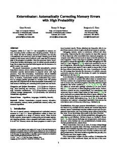
of IS customisation, i.e., of the Application-specific Functional Units (AFUs), for each application studied and (2) extension of the standard Trimaran framework [17] for compiling and simulating the resulting IS-extended VLIW machine. The target architecture REGFILE(Single/Clustered)
INTERCONNECTION NETWORK CORE SET OF FUs FU1
FU2
....
LD/ST
AFU
AFU
APPLICATION SPECIFIC FU
Memory Unit
Fig. 1. VLIW architecture augmented with application-specific AFUs
for this study is shown in Figure 1. A parametric VLIW is depicted, where the number of registers, the issue-width, and the number of Functional Units are variable. In addition, the VLIW is extended with AFUs, automatically selected within the framework. The rest of this paper is organised as follows: Section 2 compares the present study with previous contributions; Section 3 presents the overall methodology followed and the framework built. It also illustrates the various problems incurred in introducing efficient support for IS extensions in a legacy toolchain. Section 4 shows and discusses experimental results, and Section 5 will summarise our claims.
2 Related Work This work presents a detailed study of IS extended VLIW machines, and as such it will be first compared with efforts that attempt such study to some extent. An important attempt to study IS customisation for VLIW has been made in [7]. There, the authors investigate especially scalability, i.e., the varying of processor power such as number of registers and number of functional units, of a parameterized VLIW machine, and in part IS customisation. Only two simple and manual design examples are given for studying IS customisation, by adding special instructions in the same way as we add AFUs. However, the present paper gives a comprehensive study of the effect of IS customisation on VLIW, it shows benefits on a large set of benchmarks, and contains combined simulations of IS customisation and scalability. Finally, it uses automatically selected instructions, therefore showing benefits that do not require any manual intervention and detailed application study. All of the above differences also apply to two other previous studies [16, 18]. The second contribution of this paper is that of presenting a completely automatic framework, that spans from identification of IS customisation to extension of an architecture and toolchain for validation of results. Unlike the previous studies it enabled us to carry out the study of the effect of IS customisation on VLIW machines in a completely automatic way, without any designer intervention. Most previous work in customised architectures is restricted to approaches which combine a complete instruction set definition or instruction selection process, archi-
tecture creation and instruction mapping onto a newly created architecture. These approaches [20, 11] primarily create from scratch a new instruction set and a new architecture which are tuned for a set of applications. Unfortunately, the design of complete ASIPs incurs the complexity and risks of a complete processor and tool set development. A similar approach outlined in [13] describes an automated system for designing architecture and microarchitecture of a customised VLIW processor and non-programmable, systolic array co-processors. Source code (in a subset of C) for a performance-critical loop nest is used as a behavioral specification of a coprocessor. However the system lacks the ability of analyzing and evaluating the application to map portions of it onto hardware, and requires user intervention. Another tool [5] generates an HDL netlist of a VLIW architecture for a customised algorithm and allows for some design space exploration. However the tool disregards the process of evaluating the application and automatic extraction of the performance critical sections of code. The philosophy undertaken instead in our approach is that of extending an available and proven processor design (possibly including its implementation as a hard-macro in a System-on-Chip design flow) and tool set after automatic extraction of subgraphs of application, so that design efforts must focus exclusively on the special instructions and the corresponding datapath. Many readily extensible processors exist today both in academia (e.g., [14, 3]) and industry (e.g., [10, 21, 6, 8, 7]), but very limited automatic methodologies to generate the extensions are generally available. Recent works [1, 19, 2] have made some steps toward an automatic methodology for the selection of custom instructions to augment the instruction set of an extensible processor and thus maximise its efficiency for a given application program. Yet, the results of these authors are limited by one or more of the following: they use unsophisticated speedup models [1], their results are only applicable to single-issue models, and/or their instruction selection methodology is too simple [19, 2]. The approach described in [4] is an attempt to automate the process of extraction of AFUs and the implementation of a complete system. The work describes a completely automatic methodology, and shows AFU benefits for a simple VLIW architecture. Our study, in addition, tries to answer further important questions like (1) Can clusters of only dataflow operations form potentially good AFUs? (2) Is a rich VLIW architecture already powerful enough to gain anything substantial from AFUs? (3) Are ILP and Instruction set customisation complimentary?. Our work tries to prove that use of AFUs can outperform a very rich VLIW architecture at a very low cost by doing away with expensive high issue-width and large register files. We use the algorithm depicted in [1] for our automatic IS extension, but in contrast with the original results of that work, we are here able to evaluate precise speedup measurements thanks to the presence of our automatically extended compilation and simulation framework.
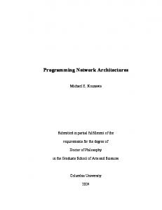
3 Overview of the Methodology and of the Validation Framework Our customised architecture synthesis methodology is composed of the following steps as shown in Figure 2: First, beneficial IS extensions are extracted from the application source code. The next step involves customisation of the processor architecture and
synthesis of the new instruction set. Finally, code is generated and simulated for the extended architecture built, and statistics are collected in order to evaluate the performance gain achieved.
Application Code Automatic Identification Of Coarse Grained Functional Units
Modification Of Application Code
Customisation Of Machine Architecture
Instruction Set Specialisation
Code Generation &
Simulation
Execution Statistics
Synthesis
Fig. 2. Customised architecture synthesis methodology
3.1 Automatic AFU Extraction The complete process of automatic extraction of coarse grained AFUs is illustrated in Figure 3. Three separate phases can be distinguished: identification of potential AFUs, based on the algorithm published in [1] and applied to the application source code; evaluation of identified AFUs, based on profiling figures and on a speedup estimation model [12]; and selection of the final best promising AFUs. The identification algorithm
Application Code Automatic Identification Of Coarse Grained AFUs HW Model SW Model Selection Criteria
Evaluation of AFUs Identified
Selection Of AFUs
Fig. 3. Automatic AFU selection
extracts promising sections of code from the basic blocks of the embedded application under study, after an if-conversion pass has been applied in order to raise the identification potential and span beyond the basic block limit to some extent. The analysis starts from the Directed Acyclic Graph (DAG) representation of the enlarged basic blocks obtained after if-conversion. Nodes of the DAG are assembler-like instructions, while edges represent data dependency among instructions. The algorithm extracts instructions satisfying user-given register-file input/output constraints that result in maximal speedup using an approximate speedup metric. It analyses the dataflow graphs and considers all possible subgraphs. The input and output
Table 1. Hardware delay and area of some operators. TSMC 0.18 um CMOS Technology and standard cells from Artisan were used. Operator Precision Relative Delay Relative Area Multiply-Accumulator 32 bits x 32 bits + 64 bits 3.00 1.000 Adder 4 bits + 4 bits 0.33 0.001 Adder 8 bits + 8 bits 0.36 0.002 Adder 16 bits + 16 bits 0.60 0.003 Adder 24 bits + 24 bits 0.72 0.005 Adder 32 bits + 32 bits 0.75 0.007 Barrel shifter 8 bits 0.24 0.002 Barrel shifter 16 bits 0.33 0.004 Barrel shifter 32 bits 0.48 0.008 Barrel shifter (by constant amount) any 0.00 0.000 Bitwise multiplexer any 0.06 0.001
requirements of the subgraphs are calculated and only those satisfying all constraints are selected for further consideration. The number of subgraphs being exponential in the number of nodes of the graph, the algorithm has an exponential worst case complexity; yet, it exploits some graph characteristics which allow significant pruning of the search space and, in practice, it exhibits a subexponential complexity. Graphs with up to a couple of hundreds of nodes can be processed in a matter of minutes. An approximate speedup estimation is then performed for the potential instructions extracted, in order to select the most promising candidates. The estimation consists in comparing the approximate subgraph execution time in software, as a sequence of instructions, with the accurate time the subgraph takes if implemented in hardware, as a single special instruction. The former number, software latency, is estimated using the baseline architecture opcode latencies, while for the hardware latencies, datapaths for all possible opcodes were synthesised and simulated in ASIC technology, and their area and delay were measured. Table 1 shows the measured hardware latency and area requirements for some operators. All delays have been expressed relatively to a multiply-accumulate, by considering that the baseline architecture can execute a multiply instruction in 3 cycles. Areas are also expressed relatively to the area of a multiply-accumulate. The total hardware latency for an AFU is calculated by summing the latency of all nodes in the critical path, and then the ceiling function is applied to it. This is also the number that is automatically passed to the machine description to define the latency of the newly introduced instructions. Note that while the hardware latency model is rather accurate, the software model does not capture possible pipeline stalls, scheduling constraints etc. However, its simplicity is due to its use in the evaluation of millions of candidate AFUs. The software model is used for the choice of AFU candidates, and not for results evaluation. Section 4 provides speedup numbers which are the result of compilation and simulation and therefore are very accurate. The last phase, selection of final AFUs, simply consists in choosing the best promising AFUs, according to the gain calculated in the previous phase (which is of course multiplied by frequency of execution, as obtained by profiling). These selected AFUs
represent the IS extension of the VLIW machine, and they are passed on to the extended Trimaran framework, with their latency and area. 3.2 Validation Framework The validation framework built is an extension of the Trimaran toolchain, which comprises a retargetable compiler and configurable simulator. The original framework provides for a parameterized VLIW architecture called HPL-PlayDoh. The HPL-PD opcode repertoire, at its core, is similar to that of a RISC-like load/store architecture, with standard integer, floating point (including fused multiply-add type of operations) and memory operations. Hence we consider the problem of extending the Trimaran infrastructure through the IS extension and the introduction of coarse-grain AFUs in the compiler infrastructure. The Trimaran framework provides IMPACT (Illinois Microarchitecture Project utilizing Advanced Compiler Technology) which serves as a compiler front end for C. It is divided into three distinct sections each based upon a different IR. Elcor forms the compiler back-end, parameterized by a machine description, performing instruction scheduling, register allocation, and machine-dependent optimizations. A cycle-level simulator of the HPL-PD architecture which is configurable by a machine description in the HMDES (High level Machine Description) format, provides run-time information on execution time, branch frequencies, and resource utilization. The first step involves defining a new machine operation and a new resource in the system. The operation will be performed by the resource which corresponds to a coarsegrain AFU in the architecture. The operation will be defined in terms of the operation format, the operation latency and the resource usage. After this, the compiler needs to be modified so that it is able to generate code for this new operation. To accomplish this, one requires a retargetable compiler parameterized with the machine description. The application code is modified so that the desired computation (to be carried out by the coarse-grain AFU) is replaced by an external function call. The Intermediate Representation (IR) of the compiler will consist of nodes corresponding to this function call. The IR is modified to replace these nodes by a new node corresponding to the operation. The compiler back-end will then treat this node as any other standard machine operation (e.g., ADD) but will generate code for it without trying to perform instruction selection. Finally, the operation semantics are defined inside the retargetable simulator so that various statistics can be generated. The diagram in Figure 4 represents the modified Trimaran framework, to incorporate the identified AFUs. The shaded portions represent the components of the framework which were modified to extend the Trimaran infrastructure. Modification of Application Code The application program in C is modified, to replace the various operations intended to be performed by AFUs with an external function call. Depending on the type of AFU required, different approaches are taken. Presently AFUs are identified as clusters of dataflow operations excluding loads and stores. Hence, the AFUs identified do not require access to memory, nor do they contain control flow operations. Note that the suitably modified application code is generated automatically.
IMPACT Modified Application Code
Pcode
Hcode
Lcode
ELCOR
Bridge Code
Recognises New Instruction
HMDES
With New Instruction
ELCOR IR
With AFU
Simulator Generator With Semantics of New Instr
Simulator
Execution Statistics
Fig. 4. Extension of the Trimaran infrastructure
Modelling of Single Output AFUs. In order to model the call to an AFU which provides a single computed value, a single function call is used; note that the overhead of a function call compared to that of a simple opcode execution is removed, as explained later. Consider the following piece of application code: main() { int a = 2, b = 3, c = 4; while (a < 100) { a = a * b + b * c;}} // Identified AFU
To model the identified AFU the application code is instrumented and the identified AFU is replaced with a corresponding function call. The function representing the AFU is automatically defined in an external library to provide the correct semantics. main() { int a = 2, b = 3, c = 4; while (a < 100) { a = fun_AFU(a, b, c); }}
int fun_AFU(int a, int b, int c) { return a * b + b * c; } // Model AFU
Once the code is instrumented this way, it can be linked with the external library containing the definitions of the function calls for the AFUs identified. It can then be compiled and executed like the original application code, and verified to produce exactly the same output. Modelling of Multiple Output AFUs. A different approach is required for modelling multiple output AFUs. Consider the following application code with the identified AFU: main() { int a = 2, b = 3, c = 4, i, d = 1; for (i = 0; i < 5; i++) { a = a * b + b * c; // Identified AFU with d = d * c - c * b; }} // 2 outputs (a and d)
The identified multiple output AFU is modelled as a combination of two single output ones; therefore, the instrumented code for the above example is: main() { int a = 2, b = 3, c = 4, i; for (i = 0; i < 5; i++) { a = fun_AFU_one(a, b, c);
int { int {
fun_AFU_one(int a, return a * b + b * fun_AFU_two(int b, return d * c - c *
int b, int c) c; } int c, int d) b; }
d = fun_AFU_two(b, c, d); fun_AFU(a, b, c, d); }}
void fun_AFU(int a, int b, int c, int d) {}
The destination registers reserved for returning the computed values of fun_AFU_one and fun_AFU_two are used as the destination registers for the final computed values. An important point to note here is that the instructions introduced for the single output component are understood only by the Trimaran front-end compiler and used only to reserve destination registers. These are dummy instructions with no actual hardware defined to execute them; the only real instruction which is bound to an AFU is the instruction represented through a function call with an empty body; in the example, it is the function call fun_AFU. Instruction Set Specialisation Once the instrumented application code is ready, the next stage involves replacing the function call with the special machine instruction to invoke the customised AFU specially designed for it. The instruction-set extension is done at the IMPACT the front-end stage of the Trimaran compiler. Among the many compilation phases of IMPACT, Hcode-level is best suited for the introduction of the new machine opcode, since function calls are easy to trap and replace, and no extra data-movement instructions (e.g., preparing the function arguments onto the stack) have been inserted till this phase. The new machine instruction introduced is recognised at the Hcode-level and at all the subsequent compilation phases of the Trimaran front-end. The interface between the Trimaran front-end compiler and the back-end compiler is modified, so that the back-end compiler can recognise the new machine instruction in the IR it receives and can schedule it accordingly. Note that the scheduler correctly accounts for the limited availability of read ports when using AFUs. The simulator too requires modifications to recognise the new machine instruction and to define the semantics of the coarse grained AFU. Modelling Register File Ports The register file design is one of the most critical design parts of a microarchitecture. The Trimaran infrastructure assumes that each functional unit has dedicated read and write ports and hence does not explicitly model them. As we introduce AFUs in the machine architecture, we assume sharing by the AFU(s) of the otherwise dedicated ports of the FUs, and hence implicitly assume that the AFUs inputs have a crossbar or multiplexers to connect them to the register file. FUs reserve a random read or write port. AFUs get also a random read or write port, and in practice will have to use exactly those private ports that the FUs are not using at that very moment. The scheduler has to guarantee that the total number of used read ports or write ports at each cycle does not exceed some bound. Any scheduled operation will require, an issue slot of the resource corresponding to the appropriate FU (e.g., an ALU for an ADD), a number of read ports at issue cycle equal to the number of operands coming from the register file and a number of write ports at completion time (e.g., on the next cycle) equal to the number of values produced. To model the above assumed architecture read ports and write ports are considered as resources in the HMDES machine description, and are required to be reserved for every operation.
Extending the Machine Architecture The machine architecture is automatically modified to introduce the new FU using HMDES machine description language which involves defining its operation format, number and type of resources (FUs and AFUs), operation latency (calculated as shown in Section 3.1), resource usage and reservation table. Finally the semantics of the new operation are defined in the simulator which involves defining the value of the destination as a function of the values of the sources. Challenges of Adding ISE Support to a Legacy Toolchain Addition of Instruction Set Extensions to a compiler toolchain framework cannot be considered to be trivial. We present here some of the issues faced during the tool chain extension. Representation of AFUs in the application code and its subsequent replacement with a machine operation forms an important part of the framework. In the present framework, if the function calls representing AFUs are allowed to propagate through various stages of compilation phases and replaced before the code scheduling, a large number of instructions are introduced to prepare the data for the function call(e.g, moving the various arguments to registers and/or stack). This forms an expensive overhead, and the simulation results fail to show any performance gain for the customised processor. However the replacement should be done after the profiling phase, as the intermediate representation is converted to code in high level language for profiling. The extended tool chain should allow aggressive ILP optimizations like loop unrolling, predication, speculative execution, modulo scheduling, formation of hyperblocks etc to be applied to the extended opcode repertoire. Performance gain should be quoted after applying such optimizations during code generation for various architectures under consideration.There could be a loss of some of the optimizations due to introduction of new machine operations. This can be traced back to the stage at which AFU identification takes place. If the identification is performed before the various compiler optimizations are done, many operations which govern optimizations like common sub-expression elimination, loop invariant code motion, dead code elimination end up in an AFU, leading to generation of sub-optimal code. Hence it is important to ensure proper phase ordering among various stages of the framework. Estimation techniques used during calculation of Speedup for the identified subgraphs, should be modified according to the base architecture. Calculation of hardware/software latencies using all the operations in the subgraph, which may be applicable to RISC cannot be applied to VLIW architecture, and may lead to poor selection of AFUs and a bad estimation of the expected speedup.The retargetable tool chain framework should accurately represent the machine architecture including the interconnection network between register files and AFUs, pipelining of customised functional units, etc. If these parameters are overlooked, the simulation results cannot be considered to be accurate. In the current framework, Trimaran was extended to support register ports to model the sharing of interconnection network between conventional FUs and AFUs.
4 Experimental Results Our complete toolchain was applied to some of the standard benchmarks of the MediaBench [15] and EEMBC [9] suite.
Table 2. Different baseline architectures with varying number of FUs and register file ports Name Integer FUs Float FUs Memory Units Branch Units Read ports Write ports 2/1/1/1 2 1 1 1 7 4 4/2/2/1 4 2 2 1 14 8 i/i/2/i infinite infinite 2 infinite infinite infinite 4/2/i/1 4 2 infinite 1 infinite infinite Table 3. Number of AFUs per benchmark, and total area occupied relative to area of a MAC Benchmark adpcmdecode MD5 g721encode autcor fft bezier AFU count 5 3 15 3 8 6 Total AFU area 1.80 0.90 3.10 1.35 5.80 10.90
The entire process consists of the following stages: (1) A first pass of compilation into the MachSUIF intermediate representation is applied, which parses the C-code into a Data/Control Flow Graph (DFG/CFG) representation. (2) Profiling is then performed and results annotated in the representation. (3) AFU identification and selection is performed by the algorithm described in Section 3.1. (4) The application code automatically annotated with the selected candidates forms an input to the next stage where the modified application code is automatically generated. (5) Finally, the automatically modified application code is fed to the extended Trimaran infrastructure for final compilation and cycle-exact simulation; the speedup obtained is thus calculated. The entire process of analyzing the application and preparing the Trimaran Infrastructure for it, is completely automatic and requires a few minutes to complete. However the time taken for cycle-exact simulation, depends on the application and its inputs and can vary between few seconds to about an hour. Experiments were carried out on different baseline architectures, equipped with a varying number of FUs and register file ports. The various architectures considered are summed up in the Table 2. AFU identification was run for a limit of 7 inputs and 4 outputs in all cases. Some typical AFUs extracted from the benchmarks are depicted in Figure 5. The AFUs of type as shown in Figure 5(b) are extracted quite frequently and used to compute addresses for memory accesses. 4.1 Impact of AFUs on the Area The benchmarks used and the number and total area of AFUs selected for each of them are described in Table 3. The area of an Integer ALU unit in HPL-PD architecture can be calculated to be 1, relative to the area of the MAC instruction. Hence it can be noted that the total area added for customisation (calculated as described in Section 3.1) is in most cases very limited. It is worth noting that the use of AFUs reduces the length of the application program, since an AFU is a single instruction replacing a number of operations. Figure 6 quantifies the decrease in the size of the program (shown as number of total operations) when AFUs are employed, for two different baseline architectures. Note that some of
s1
s2
+
0