Automatically Generating Custom Instruction Set Extensions Nathan Clark
[email protected]
Wilkin Tang
[email protected]
Scott Mahlke
[email protected]
Advanced Computer Architecture Lab Department of Electrical Engineering and Computer Science University of Michigan Ann Arbor, MI 48109-2122
ABSTRACT General-purpose processors that are utilized as cores are often incapable of achieving the challenging cost, performance, and power demands of high-performance audio, video, and networking applications. To meet these demands, most systems employ a number of hardware accelerators to off-load the computationally demanding portions of the application. As an alternative to this strategy, we examine customizing the computation capabilities of a core processor for a particular application. Our goal is to enable some or all of the computation that is off-loaded to the accelerators to be taken over by the customized core. The computation capabilities of the core processor are extended with hardware in the form of a set custom function units and new instructions. The compiler is responsible for analyzing the target application and identifying a set of cost-effective custom function units. In this paper, we provide an overview of the system that we are developing to automatically identify instruction set extensions and report some preliminary analysis of four media benchmarks.
1. INTRODUCTION In recent years, the markets for PDAs, cellular phones, digital cameras, network routers and other high-performance but special-purpose devices has grown explosively. Many of these devices perform computationally demanding processing of images, sound, video, or packet streams. In these systems, application specific hardware design is used to meet the challenging cost, performance, and power demands. The most popular design strategy is to build a system consisting of a number of special-purpose ASICs coupled with a low cost core processor, such as an ARM. The ASICs are specially designed hardware accelerators to execute the computationally demanding portions of the application that would run too slowly if implemented on the core processor. While this approach is effective, ASICs are costly to design and offer only a hardwired solution that permits almost no postprogrammibility. An alternative design strategy is to augment the core processor with special-purpose hardware to increase its computational capabilities in a cost effective manner. The instruction set of the core processor is extended to feature an additional set of operations. Hardware support is added to execute these operations in the form of new function units or co-processor sub-
systems. There are a couple of benefits to this approach. First, the system is postprogrammable and can tolerate changes to the application. Though the degree of application change is not arbitrary, the intent is the customized processor should achieve similar performance levels with modest changes to the application, such as bug fixes or incremental modifications to a standard. Second, some or all of the ASICs become unnecessary if the augmented core can achieve the desired level of performance. This lowers the cost of the system and the overall design time. The key questions with this approach are whether the augmented core can achieve the desired level of performance and how to design an efficient set of extensions for the processor core. For this paper, we focus on the latter question wherein the goal is to define a set of instruction set extensions to accelerate a target application in a cost-effective manner. This process can be as time consuming and expensive as designing an ASIC if done manually, thus we believe automation is a key to making this strategy successful. Our approach is to use the compiler to identify the critical computation subgraphs in the application. The subgraphs are analyzed to determine the desirability of using specialized hardware to accelerate them. A number of issues must be considered to determine desirability, including estimated performance gain, estimated cost of the custom hardware, encoding of the new operation in the core processors instruction format, and expected usability of the custom hardware. With this data in place, a set of hardware extensions to processor are selected and the compiler generates code with the selected subgraphs replaced by new instructions. This paper presents a work-in-progress of the customized processor design system that is being developed at the University of Michigan. We focus on the issues associated with designing application-specific instruction set extensions and give an overview of our current system. We also present several case studies of embedded applications to illustrate the cost / performance tradeoffs of augmenting a core processor.
1.1 Related Work A large body of research has gone into the automatic design of instruction sets. The earliest work focused on generating CISC-like instructions to more effectively support high-level languages and increase code density [1] [2]. Efficient algorithms for instruction selection for processors with CISC instructions have also been proposed [3] [4]. High-level synthe-
sis systems address the issue of automatically designing specialized datapaths to suit an application [5]. Instruction set synthesis identifies the best instruction set for a fixed datapath [6]. The ASIA system extends the previous work to integrate instruction set synthesis and code generation [7]. The use of custom instructions is common in reconfigurable computing. Large functional blocks are identified and mapped to reconfigurable hardware in the PRISM and GARP systems [8] [9]. A more fine-grained approach is taken in the PRISC and DISC projects wherein smaller units of work are identified and the reconfigurable hardware is utilized as specialized function units [10] [11]. Some recent systems propose the automated design of application-specific VLIW processors. These systems focus on customizing the function unit mixture, cache subsystem, instruction format, and fetch / decode path [12] [13]. Cryptomaniac is one specific example of a VLIW application specific processor targeted to the security domain that achieves around a 30% performance gain utilizing specialized instructions [14]. Previous work in the area of compiler identification of custom instructions looked for sequences of operations that were suitable for chaining [15]. In [16], a large set of potential chainable operations are identified during compiler analysis. Then, the instruction scheduler makes the final chaining decisions. Our work is probably most similar to Arnold who investigated application-specific instruction set extensions for the MOVE architecture [17]. He identified commonly occurring operation patterns, created specialized function units, and generated code to make use of the new function units. Our work differs from Arnold’s in that we consider more generalized subgraphs, use a compiler-driven approach rather than a trace-driven approach, and examine more cost/performance tradeoffs involved with selecting custom instructions.
2. CUSTOMIZATION ISSUES We loosely define a custom function unit (CFU) to be the hardware implementation of a set of primitive operations that are connected in a dataflow graph. Primitive operations are assembly operations for a generic RISC architecture, such as Add, Or, Load. No assumptions are made regarding the connection of the graph nodes, so linear, tree shaped, or even cyclic graphs can be implemented as custom function units. Disconnected graphs are not considered, however. Each primitive operation has three values associated with it (delay, cost, and IO format) that are used to identify candidate CFUs. The delay is propagation time through the longest path in the preferred hardware realization of the opcode. Operation delays are summed and combined with the clock frequency to determine an estimate of the latency of a CFU in terms of clock cycles. Cost is an area estimate for the hardware cell that implements the opcode. Lastly, IO format are the input/output requirements and restrictions for the source and destination operands of the opcode. In selecting a set of CFUs for an application, as with any engineering problem, it is important to balance several trade-offs. We characterize the trade-offs associated with CFUs in four categories: performance, cost, IO requirements, and usability. In this section, we discuss these trade-offs and illustrate each
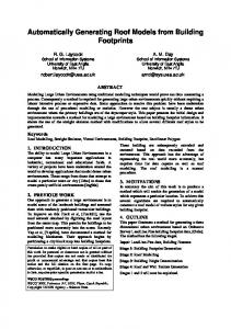
with an example from the dataflow graph (DFG) in Figure 1. While this example is contrived, it is similar to dataflow graphs we saw in several encryption benchmarks. Performance: The most compelling reason for adding CFUs to a processor is the potential for increased performance. The realization of performance gain is determined by two factors. First, the implementation of the DFG as a CFU must require fewer cycles than if the primitive operations are executed individually. This is not a problem for many operations as their hardware implementation is simple. For instance, logical operations are one level of logic, thus it is trivial to chain several of them into one cycle and still meet timing constraints. Many arithmetic operations are also strong candidates for chaining as processor cycle times are not often constrained by the ALU speed. The second factor that must occur to achieve performance gain is that the critical dependence path(s) of the target code block must be reduced with the introduction of CFUs. CFUs that reduce non-critical portions of the code will have little effect on overall performance. This is a more important consideration for processors that exploit instruction-level parallelism. Assuming each node in Figure 1 has a latency of one cycle, the DFG takes a minimum of eight cycles to execute (i.e., the critical dependence path is nodes 1, 2, 3, 4, 7, 8, 9, 10). Consider creating a CFU for nodes 5 and 6. This is a poor choice because this graph would still take at least 8 cycles to execute as nodes 5 and 6 are not on the critical path. Further, variable bit shifts (node 6) typically have a large delays as barrel shifters are complicated hardware cells. As a result, it is likely that the CFU for nodes 5 and 6 would not reduce the two-cycle latency required to just execute the primitive operations. A better CFU choice is nodes 1, 2, 3, 4. This subgraph is ideal from the performance perspective because it occurs on the critical path and all its constituent operations are relatively simple (subtract, shift by constant, and logical). Thus, its highly likely to reduce this four cycle subgraph into a one cycle CFU. An important is issue to consider during the CFU selection process is that once a CFU is selected, the critical path could potentially change. For example, if we instantiated CFUs 1 and 2 from Figure 1 and were able to execute them in one cycle each, the critical path would change to go through nodes 5 and 6. Any attempt to create new CFUs for patterns along the old critical path would be fruitless and it would still take four cycles to execute the code. Cost: We consider cost to be the die area impact on the processor from adding the CFU. This metric should be the sum of the area of the CFU, the additional inter-connect and control logic, the impact on decode logic, and the change in register file area to support the CFU. Register file cost increases can be amortized across multiple CFUs, though, and it is difficult to measure the impact on decode and control logic. Because of this, we make the simplifying assumption that CFU area is the dominant term of the equation. Further, the estimated code of the CFU is the sum of the hardware implementation costs of each primitive operation that comprises the CFU. The goal with respect to cost is to maximize the other design constraints for a given cost. Therefore, when selecting CFUs, pat-
Reg 1
Reg 2
Custom Opcode 1
SUB : 1 16 LSL : 2
Reg 3 AND : 3
XOR : 4
Reg 4
ADD : 5
Custom Opcode 3 LSL : 6
SUB : 7 Output 1
16 LSL : 8
Output 2
Output 3
AND : 9
XOR : 10 Output 4
Custom Opcode 2
Figure 1: Example dataflow graph.
terns that contain mostly inexpensive operations are the ideal candidates. Custom Opcodes 1 and 2 in Figure 1 are a good example of this: there are two logical operations, a subtracter, and one shift by a constant, none of which require very much area. Compare this with the cost of implementing Custom Opcode 3, with its expensive barrel shifter in node 6, and it is easy to pick which CFU is better to implement assuming they both give you the same speedup and you are optimizing for performance. IO requirements: The IO requirement for a CFU is the number of inputs and outputs needed for the CFU. This property has ramifications in three areas. First, instructions with large number of inputs and/or outputs are difficult to represent in a conventional instruction set, because the number of bits necessary to encode a large number of sources and destinations. The processor fetch and decode paths may not be capable of handling a new instruction format that differs greatly from its baseline instruction formats. Large numbers of inputs and outputs may also require an increased number of ports on the register file. The cost of register files increase with the square of the number of ports, so this can have a major impact on the cost of the overall processor. Lastly, if you have two operation graphs you want to generate CFUs for that are identical except for the number of inputs or outputs, it is necessary to decide whether you want to create two separate CFUs, or one CFU that has the maximum inputs and maximum outputs over the two instances. As an example, if we pick Custom Opcode 1 and Custom Op-
code 2 from Figure 1, Custom Opcode 1 will have two inputs and two outputs, whereas Custom Opcode 2 will have two inputs and one output. A decision has to be made whether to implement both of these on a single CFU with two inputs and two outputs, or implement them separately. In this case, it would probably make more sense to create one CFU, but what if Custom Opcode 2 had three inputs? If we were implement Custom Opcode 3 instead of 1 and 2, the number of inputs and outputs will increase to four each, and we would probably have to add ports to the register file to support the custom opcode. The encoding four sources and four destinations in an instruction may be prohibitive in cost or not even possible and thus must be considered. Usability: The most abstract and difficult of the issues to quantify is the usability of the CFU. Usability refers to the degree to which the compiler can recognize candidate subgraphs to execute on the CFU. This issue is important because we are striving for a postprogrammable system in which the CFU can be utilized by either similar applications or future generations of the analyzed application. Usability generally has an inverse relationship to the size and regularity of the DFG. Thus, larger and more irregular CFUs are more difficult to make use of by the compiler. Usability concerns must counterbalance performance concerns. From the performance angle, large subgraphs are the most desirable as they offer the best potential for speedup. The ability to collapse many nodes onto a single CFU leads to the largest reductions in the critical path length. In Figure 1, this code
segment would execute most efficiently if the entire subgraph was converted into a CFU, thereby selecting Custom Opcode 3 as a CFU. However, finding repeated occurrences of this subgraph is a difficult task for the compiler due to its complexity. Further, larger subgraphs are more susceptible to small source code changes that could obsolete a carefully designed CFU. For example if node 5 is converted from an Add to a Multiply with a new version of the algorithm, a CFU for Custom Opcode 3 would be worthless. In our current system, we have empirically seen that a good indication of usability is CFU utilization. A CFU that is not used effectively within the target application is often a poor choice for a CFU. Obviously, it is easy to find exceptions to this behavior and we are investigating more precise ways to quantify usability.
3. CASE STUDIES We ran four benchmarks through our automated CFU generation system to demonstrate the potential performance gains an application specific processor can achieve with CFUs. The first three benchmarks we used are all part of the MediaBench [18] program suite. G721encode is an implementation of the CCITT (International Telegraph and Telephone Consultative Committee) G.711, G.721, and G.723 voice compression algorithms. Rawdaudio is an audio decompresser and part of the ADPCM family of speech compression algorithms. The ADPCM algorithms are more complicated than the G721 ones, and convert 16-bit linear PCM samples to 4-bit samples. The djpeg benchmark is a utility for jpeg format image decompression. Our final benchmark is an encryption algorithm that is part of the MiBench [19] suite. Blowfish is a symmetric block cipher that is meant as an alternative to DES or IDEA. All of these benchmarks are computationally intense and spend most of their execution time in a small number (usually one to three) of functions, which make them prime candidates for CFUs. Since our CFU generation system is still in its infancy, the focus of this section will not be on what types of CFUs are being generated or how they are selected, so much as it will deal with the potential of CFUs in application specific processors. Despite this, we should address this point briefly. As one might expect, ADD-LOAD and ADD-STORE were commonly generated CFUs, because of the prominence of base plus displacement memory accesses. ADD followed by a COMPARE instruction was also fairly common. Many of the CFUs generated were not so obvious, however. For example, the one CFU generated for blowfish was a chain of the following ten operations: ADD-XOR-ADD-AND-XOR-SHIFT (by a constant)AND-ADD-SHIFT (by a constant)-ADD. This chain only had six inputs and two outputs, and occurred in 35 unique locations in blowfish’s DFG. This accounted for almost seven million cycles of the critical path. These operations can be compressed from ten down to two cycles according to our timing models, which could potentially yield a tremendous speedup. Clearly, even with our naive pattern recognition system, CFUs could yield major performance benefits. In each of our experiments, we show speedup of a baseline machine plus CFUs compared with the baseline machine alone. Our baseline machine is a four-wide, pipelined VLIW, machine with predication support, single cycle L1 cache latency, and a 300 MHz clock. It is necessary to assume some clock
speed in order to determine how many cycles a CFU will need to execute. The baseline machine can issue at most one integer, one floating point, one memory, and one branch instruction per cycle, but since all of our benchmarks are integer based this is essentially a three issue machine. We make the assumption that CFUs do not add parallelism to the baseline machine; that is CFUs use an integer execution slot, and compete for the same register ports as all the other instructions in the machine. A convincing argument could be made that by using an integer execution slot for CFUs such as ADD-LOAD, we are actually increasing the parallelism of the machine by using a second memory unit through the integer issue slot. The benchmarks we experimented on tended to be computationally bound (not memory bound), though, so using a memory issue slot for this type of CFU made a negligable difference in our measured speedups. When there was a difference, using the memory issue slot, actually tended to improve our measured speedup slightly. Performance of the benchmarks is measured by multiplying the profile weights of each basic block by the number of cycles it takes to execute the block and summing the number of cycles over the entire program. Figure 2 shows the results for our set of benchmarks. The left four graphs in the figure vary the maximum number of operations allowed in the CFU, while allowing generation of an unlimited number of unique CFUs. The right four graphs vary the number of CFU generated, while allowing them to be any number of operations in length. Cost of the CFUs and the speedup of the program are represented as the two curves each graph. The idea to take away from the left four graphs is that as we increase the maximum number of operations allowed in a CFU, the speedup generally increases. This occurs because we have more opportunities to combine operations into a single cycle. After a certain point however, there is a diminishing return on our cost (and even some decrease in speedup such as in g721encode) when the number of operations becomes large. This results because once we combine an instance of an operation into a particular CFU, we can no longer execute that operation it in a different one. In other words, if you select a large CFU, you are taking away the opportunity to group its constituent operations with operations that are not part of the CFU. This is the tradeoff of generating one large CFU versus several smaller ones. Speedup decreases when our CFU selection algorithm (described in Section 4) incorrectly chooses a large CFU, when several smaller CFUs would have been the better choice. The right four graphs in Figure 2 demonstrate the obvious fact, that as we increase the number of CFUs in the system, performance increases. The more important point from these graphs to note is how performance increases. This is a direct measure of the quality of our CFU selection algorithm. Ideally if we could only select N CFUs, we would want to select the set that gave us the best speedup. Since the biggest leaps in performance speedup do not always occur in the first few CFUs selected, we see that our selection algorithm needs some work. Another interesting fact to note from the right set of graphs is that djpeg did not see a incredibly large speedup until we went
Figure 2: Relative speedup and cost when varying the maximum operations allowed in a CFU, and the number of CFUs allowed in an application. Cost is measured relative to the area of one 32-bit ripple-carry adder.
to a very large number of CFUs. This occurred because djpeg made use of several smaller CFUs while the other benchmarks got their greatest speedups from a few large CFUs.
4. OUR SYSTEM The goal of our system is to automate the process of selecting and synthesizing CFUs for an application specific processor. This is accomplished in six stages, which are diagrammed in Figure 3. This section of the paper describes both the current functionality of the CFU discovery and selection process (steps two - five), as well as where we envision this system going in the future. The compilation and synthesis steps of the process are beyond the scope of this paper. Step1: The initial step of CFU generation is custom opcode pattern recognition, to get an idea of what CFUs are potentially useful. For all of our experiments, we take a profiled, assembly language program (in the HPL-PD instruction set [20]) as input. Given this program, we construct a dataflow graph, and initialize the set of custom opcode patterns to be each individual operation. Other pattern recognition techniques, such as [7], further broke down the assembly code into what they termed ‘micro-ops’ and did pattern recognition on those, but this is unnecessary in our situation as each of the HPL-PD primitives are sufficiently simple to build in hardware. If we were using a more complex instruction set (e.g. x86), this would not be the case. After initialization, we then recursively expand the custom opcode patterns along dataflow edges in a depth first manner. For example, in Figure 1, if we were to start at node 7, we would add a new pattern for nodes 7-8, nodes 7-8-9, nodes 78-9-10, and nodes 7-10. Currently, we do not track data flow through memory, as pointer chasing in C code is very difficult, but this is certainly possible when memory accesses are all done through arrays. This optimization is left as a potential improvement for the future. Our depth first expansion terminates when there are no more data flow edges from the operation (e.g. we reach a store instruction), the destination of the data flow edge is a branch, the destination is a load, or there is a branch between the dataflow edge’s source and destination operations. Terminating at load instructions is done because the non-deterministic latency of the memory system makes it impossible to determine what other operations can be done to the result of the load while still meeting cycle time limitations. Branch instructions cause termination of the expansion because after the branch the intermediate operands are only conditionally used. That is, if we have an instruction whose result feeds a second instruction on the other side of a branch, we may need to write the result of the first instruction to the register file, because the second instruction will not always be executed. Exposing these intermediate results as outputs from our CFU could potentially cause the register porting requirements to become unwieldy, and would nullify the reduction in register pressure we gained from not having to write intermediate results to the register file. Regardless of this fact, if we had operations in a CFU that spanned branches, it would be necessary to add control to the CFU to conditionally execute operations that happened on the other side of the branch. Terminating custom opcodes at
branch boundaries differentiates us from [6] and [17], as both of these approaches do pattern matching on an execution trace, instead of a control flow graph. One limitation of our current pattern recognition algorithm is that currently, we are only looking at straight-line chains of operations; that is, an intermediate result is only forwarded to one other operation within the CFU we generate. This restriction is completely artificial, and we plan to remove it in the future. A more concrete restriction of our system is that we only recognize patterns that start with a single node. This restriction is an artifact from starting our pattern with a single node and only growing with a depth first search. We do not see this as a weakness in our algorithm, though. As discussed in Section 2, ideally the CFUs we generate would have few inputs; requiring a single starting operation is one way to artificially push our solutions in that direction. Step2: After pattern recognition comes the CFU characterization phase, where we get a general idea of each CFU’s potential utilization in the application, register port requirements, cost (measured as die area), timing, and power characteristics. A rough idea of CFU utilization can be garnered from the execution profile weights of the operations that form the custom opcode pattern in the control flow graph. To determine the other characteristics, we need to actually generate the hardware. Cost, timing, and power characteristics of most primitive operations in the HPL-PD instruction set are stored in an external macrocell library and fed into our system. The macrocells were synthesized using Synopsis Design Compiler and an Artisan component library for a “typical 0.18 micron TSMC process.” Currently, the characteristics of the CFU are defined as the sum of the characteristics of its constituents (i.e. an ADD-NOT custom would have the latency of an ADD primitive followed by a NOT primitive), even though empirical evidence shows this to be overly pessimistic. Because of this, our performance results are definitely understated. Step3: Once the characteristics of the CFUs are generated, we send them to a filter function that removes any bad candidates. A candidate could be considered bad for many potential reasons, including but not limited to unreasonable register port requirements, combining the operations did not yield any cycle time decrease, potential utilization of the CFU would be too low, or encoding the instruction in the ISA would require too many bits. In the present implementation, we only filter CFUs if there were no occurrences of them on the critical path in the initial control flow graph. This restriction also potentially understates our results, because implementing one CFU might cause another path to become critical. We could have potentially reduced the length of this new critical path, too, if we had not filtered out its CFUs. Step4: After filtering is performed we select which CFUs to implement. Selection is fairly straight forward and can be a function of any of the characteristics we have mentioned. For example we could potentially select the CFUs that give us the biggest speedup for a given cost, or the ones that improve our energy-delay product most. In all our experiments we used a greedy algorithm to select the CFUs with the greatest potential speedup (measured as the product of the number of in-
Figure 3: The design flow of our CFU generation system.
stances of the custom opcode pattern on the critical path and the number of cycles gained by combining the primitive operations into one CFU) for a given die area. In other words the best performance improvement for the least cost. Output: Next, the functionality of the selected CFUs is translated into both a hardware intermediate language and a C-level description of each CFU’s functionality. Our simulator uses the C-level descriptions to model how the CFU will functionally behave when we execute it. The hardware intermediate language is used by the synthesizer to create hardware description language (HDL) code for a processor with these CFUs. In addition to the HDL, the synthesizer also generates a machine description of the processor that is fed back to the retargetable compiler. Whenever we compile for this customized machine, the same graph matching algorithm described above is used to construct potential candidates. These candidates are then compared to the graphs specified in the machine description, and any matches are replaced by custom opcodes in the final program. This technique allows us to take advantage of the CFUs with no intrusion into the compiler’s code generation algorithm.
5. CONCLUSION AND FUTURE WORK Currently our CFU generation system recognizes and generates CFUs for linear acyclic graphs. Our vision is to extend the system to recognize general acyclic graphs with more exotic structures, and simple cyclic subgraphs. For example, one application we looked at spent a considerable amount of time in a loop that was simply counting the number of bits set in an integer. This loop would be a prime candidate for replacement with a single CFU, as we could easily implement this functionality with simple combinational logic. Adding residual state to CFUs is also something we plan to investigate. Many CFUs are utilized in loop bodies where their result is fed back into them as an input for the next loop iteration. If the CFU were
to remember the last result it computed, we would not need to communicate that value through the register file. A final improvement we are looking into is better selection algorithms. From the graphs in Section 3, it is clear that our current greedy selection method leaves something to be desired. We have shown in this paper that even with naive graph recognition techniques, large speedups (as high as 2.2) are possible by using automatically designed custom function units. This technology provides engineers with a quick, cost effective way to meet the ever increasing demand on computational resources in embedded spaces.
6. REFERENCES [1] P. Bose and E. S. Davidson, “Design of instruction set architctures for support of high-level languages,” in Proceedings of the 11th Annual International Symposium on Computer Architecture, June 5–7, 1984. [2] J. P. Bennett, A Methodology for Automated Design of Computer Instruction Sets. PhD thesis, University of Cambridge, 1988. [3] S. Liao, S. Devadas, K. Keutzer, and S. Tjiang, “Instruction selection using binate covering for code size optimization,” in International Conference on Computer-Aided Design, pp. 393–399, 1995. [4] R. Leupers and P. Marwedel, “Instruction selection for embedded DSPs with complex instructions,” in Eurpoean Design Automation Conference, Sept. 1996. [5] W. Geurts, F. Catthoor, S. Vernalde, and H. D. Man, Accelerator Data-Path Synthesis for High-Throughput Signal Processing Applications. Boston, MA: Kluwer Academic Publishers, 1996. [6] B. Holmer, Automatic Design of Computer Instruction Sets. PhD thesis, University of California, Berkeley, 1993. [7] I. Huang, Co-Synthesis of Instruction Sets and Microarchitectures. PhD thesis, University of Southern California, 1994. [8] P. M. Athanas and H. S. Silverman, “Processor reconfiguration through instruction set metamorphosis,” IEEE Computer, vol. 11, no. 18, 1993.
[9] J. R. Hauser and J. Wawrzynek, “GARP: A MIPS processor with a reconfigurable coprocessor,” in Symposium on FPGAs for Custom Computing Machines, Apr. 1997. [10] R. Razdan and M. D. Smith, “A high-performance microarchitecture with hardware-programmable function units,” in Proceedings of the 27th Annual International Symposium on Microarchitecture, pp. 172–180, Nov. 30–Dec. 2, 1994. [11] M. J. Wirthlin and B. L. Hutchings, “DISC: The dynamic instruction set computer,” in Field Programmable Gate Arrays for Fast Board Development and Reconfigurable Computing, pp. 92–103, 1995. [12] J. A. Fisher, P. Faraboschi, and G. Desoli, “Custom-fit processors: Letting applications define architectures,” in Proceedings of the 29th Annual International Symposium on Microarchitecture, pp. 324–335, Dec. 2–4, 1996. [13] S. Aditya and B. R. Rau, “Automatic architecture synthesis and compiler retargeting for VLIW and EPIC processors,” Tech. Rep. HPL-1999-93, HP Laboratories, 1999. [14] L. Wu, C. Weaver, and T. Austin, “Cryptomaniac: A fast flexible architecture for secure communication,” in Proceedings of the 28th Annual International Symposium on Computer Architecture, pp. 110–119, June 2001. [15] F. Onion, A. Nicolau, and N. Dutt, “Compiler feedback in ASIP design,” tech. rep., University of California, Irvine, Sept. 1994. [16] M. Sivaraman and S. Aditya, “Cycle-time aware architecture synthesis of custom hardware accelerators,” in Proceedings of the 2002 International Conference on Compilers, Architecture, and Synthesis for Embedded Systems, Oct. 2002. [17] M. Arnold, Instruction Set Extensions for Embedded Processors. PhD thesis, Delft University of Technology, 2001. [18] C. Lee, M. Potkonjak, and W. Mangione-Smith, “MediaBench: A tool for evaluating and synthesizing multimedia and communications systems,” in Proceedings of the 30th Annual International Symposium on Microarchitecture, Dec. 1997. [19] M. R. Guthaus, J. S. Ringenberg, D. Ernst, T. M. Austin, T. Mudge, and R. B. Brown, “MiBench: A free, commercially representative embedded benchmark suite,” in IEEE 4th Annual Workshop on Workload Characterization, Dec. 2001. [20] V. Kathail, M. Schlansker, and B. Rau, “HPL PlayDoh architecture specification: Version 1.0,” Tech. Rep. HPL-93-80, Hewlett-Packard Laboratories, Feb. 1993.