This paper introduces Simulink Code InspectorTM, a novel tool to automate manual ..... comprising of 37 pages of diagrams against 1200 lines of ADA code.
Automating Code Reviews with Simulink Code Inspector Mirko Conrad, Matt Englehart, Tom Erkkinen, Xiaocang Lin, Appa Rao Nirakh, Bill Potter, Jaya Shankar, Pete Szpak, Jun Yan, Jay Clark The MathWorks, Inc., Natick, MA, USA Abstract: Safety standards such as DO-178B require source code reviews. Given the maturity of today‟s code generators, the effectiveness of manual reviews of automatically generated code is rather limited. This results in a strong desire to automate reviews of automatically generated code. This paper introduces Simulink Code InspectorTM, a novel tool to automate manual code reviews of C source code generated from Simulink® models.
1 Code Reviews according to DO-178B DO-178B [DO-178B] is a certification standard for civil aviation published in 1992. It provides “guidelines for the production of software for airborne systems and equipment that performs its intended function with a level of confidence in safety that complies with airworthiness requirements”. To detect and report errors that might have been introduced during the software coding process, DO178B requires reviews and analyses to “confirm that the outputs of the software coding process are accurate, complete and can be verified” (cf. DO-178B, section 6.3.4). The objectives of software code reviews are detailed in DO-178B, table A-5. A common approach to satisfy these objectives is to carry out manual reviews of the source code. Manual code reviews are labor intensive and in case of automatically generated code typically not very effective. Practitioners estimate that about 50 lines of source code (LoC) can be reviewed in a one hour period, resulting in engineering costs of $150. Projected onto a 100.000 LoC project, the source code review would last 2000 hours and cost $ 0.3 million. Given the maturity of today‟s code generators, the efficacy of manual review of automatically generated code is quite limited. [Pot04] e.g. reports about the certification of DO-178B flight code at Honeywell. The amount of code certified exceeded 1.000.000 LoC per year. The study reports that only one code generation error was found in a one year time period. Using the above cost estimates, this would translate to a cost of $ 3million to find one bug. These numbers speak for themselves. The low efficacy of manual reviews of generated code creates a high demand for automating the code review process.
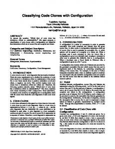
2 Simulink Code Inspector Overview To automate reviews for source code developed from Simulink models, the authors developed Simulink Code Inspector [SLCI] a novel tool to automate code reviews required by DO-178B and other functional safety standards. Simulink Code Inspector carries out a translation validation of C code generated from a Simulink [Simulink] model using the Embedded CoderTM [ECoder] code generator. In particular, SLCI systematically examines blocks, parameters, and settings in a Simulink model to determine whether they are structurally equivalent to operations, operators, and data in the C source code generated from the model (Fig. 1). Inputs to Simulink Code Inspector are a Simulink model and the C source code generated by the Embedded Coder code generator for this model. SLCI processes these two inputs into internal representations (IRs), called model IR and code IR. These IRs are transformed into normalized representations to facilitate further analysis. In this process, the model IR represents the expected pattern, whereas the code IR constitutes the actual pattern to be verified. To verify the generated code, SLCI attempts to match the normalized model IR with the normalized code IR. In this process SLCI examines aspects such as model interface, block behavior, block connectivity, execution order, data / file packaging, and usage of local variables.
Simulink model
C source code
Embedded Coder
Code IR
Model IR
IR transformations Normalized Model IR
Normalized Code IR
Matching
Code inspection report
?
Traceability report
Figure 1. Code Inspection Approach
The utilization of normalization techniques allows to inspect code generated by an highlyoptimizing code generator. The results of this matching process are reported to the user by means of a verification report and a traceability report. In case of a completed code inspection, the verification report documents the translation validation process whereas the traceability report maps the model elements onto their counterparts in the generated code and vice versa. The reports generated by Simulink Code Inspector are used as evidence to document the automated code review process. Upon DO-178B verification tool qualification, SLCI significantly reduces time and cost associated with verifying code against requirements. Instead of completing manual line-by-line code reviews with a project checklist, which is time intensive and error prone, users can run the Code Inspector and review a detailed inspection report.
3 Example: Roll Axis Autopilot Model In this section we illustrate the usage of Code Inspector by using the example of a Roll Axis Autopilot model and the C code generated from this model. Simulink Code Inspector can be invoked from a graphical user interface or via a MATLAB command line API. To kick-off the code inspection, the user can launch a compatibility checker that helps to identify modeling constructs and tool settings that are not supported by the Code Inspector. The compatibility checker leverages the Model Advisor infrastructure [MdlAdv] to statically analyze the model. If applicable, the compatibility checker also provides suggestions on how to replace incompatible modeling constructs with ones supported by the tool. After passing the compatibility check, the user can initiate the actual code inspection process. The tool can be configured to check an individual model or an entire hierarchy of referenced models. Fig. 2 (left) shows the top level of the Simulink model of a roll axis auto pilot representing the low-level requirements for the auto pilot functionality. In this example, the auto pilot functionality is represented by three different models, the top level model and separate referenced models for the HeadingMode and BasicRollMode calculations.
Figure 2. Roll Axis Autopilot Model – Top Level (Left) and Code Inspection Overview (Right)
If the code has been generated previously, it can be retrieved from the configuration management system. Alternatively it can be generated on-the-fly prior to the actual code inspection process. The code inspection results are presented in a hierarchical manner. An overview report provides aggregated status information and links to the detailed results for each model in the hierarchy (Fig. 2, right). The detailed results are divided into two parts, verification report (Fig. 3) and traceability report (Fig. 4). Verification report
Figure 3. Code Inspection Report – Verification Report for the Top-level System
Traceability report
Figure 4. Code Inspection Report – Traceability Report for the Top-level System
The verification report features information about verification of the interfaces of generated code functions, verification of structural equivalence between model and code, and usage of temporary variables. The example in Fig. 3 shows a result for generated code that is structurally equivalent to its corresponding model. Model elements that are outside of the supported language subset and corresponding code fragments would be indicated as „not processed‟ in the verification report. The traceability report documents the code lines that implement a particular model element and the model elements that contributed to the generation of a line of code. The lower part of Fig. 4 shows parts of code-to-model traceability information provided by SLCI.
To illustrate the error detection capabilities of Simulink Code Inspector, we‟ll intentionally modify the generated code (i.e. carry out a code mutation) to simulate a bug in the generated code. Then we‟ll carry out a code inspection of the original model against the modified code. This process is illustrated in Fig. 5. The upper left part of the figure shows a lower level of the RollAngleReference subsystem model. The algorithm contains an OR block indicated using red color. The upper right part of Fig. 5 shows the line of code implementing the OR block. To simulate a code generation bug, we create a code mutation that replaces the „||‟ operator with the „&&‟ operator. The lower parts of the figure show a section of the model-to-code verification results for the corresponding model. The report indicates that the matching process was not successful, i.e. Simulink Code Inspector did not find an expected code pattern for the OR block. Code mutation if ((U_Phi >= 6.0) || (U_Phi = 6.0) && (U_Phi