Geoderma 262 (2016) 133–139
Contents lists available at ScienceDirect
Geoderma journal homepage: www.elsevier.com/locate/geoderma
Automating double ring infiltrometer with an Arduino microcontroller M. Fatehnia a,⁎, S. Paran b, S. Kish c, K. Tawfiq a a b c
Department of Civil and Environmental Engineering, FAMU-FSU College of Engineering, 2525 Pottsdamer Street, Tallahassee, FL 32310, USA Department of Electrical & Computer Engineering, FAMU-FSU College of Engineering, 2525 Pottsdamer Street, Tallahassee, FL 32310, USA Department of Earth, Ocean and Atmospheric Science, Florida State University, 1017 Academic Way, Tallahassee, FL 32306, USA
a r t i c l e
i n f o
Article history: Received 12 March 2015 Received in revised form 10 August 2015 Accepted 13 August 2015 Available online xxxx Keywords: Double ring infiltrometer Arduino microcontroller eTape™ MOSFET switch Hall effect sensor Peristaltic pump
a b s t r a c t In this paper, we describe the designed and tested system of automated double ring infiltrometer (DRI) that we have developed using an Arduino microcontroller, a Hall effect sensor, a peristaltic pump, a water level sensor, and a constant-level float valve. The system can be used for infiltration measurements in both single ring falling head and double ring constant head methods. The precise measurements of the current method compared to previous designed systems are not affected by sunlight, and due to the method of flow measurement, remain accurate even for low infiltration values. The set-up has an easy real-time data storage on a micro-SD card without a need of a portable computer in the field. It only requires a single reservoir for both inner and outer rings to which, water can be added anytime needed without affecting the measurements. The system automatically detects when the steady state infiltration rate is reached and concludes the testing and stops measurements. The system is mounted in a portable and weather resistant box and is applied to run DRI testing in the field to check the applicability and accuracy of the portable set-up in field measurements. Manual testing was also performed in the field for comparison with the automated system measurements. Overall system architecture, and the design of hardware and software components are presented in details. The system configuration is illustrated for better understanding of the set-up. Published by Elsevier B.V.
1. Introduction Double ring infiltrometers are among the common test methods for in-situ measurement of the soil infiltration rate. DRI test described by ASTM D3385 consists of open inner and outer cylinders that should be manually inserted into the ground and be partially filled with a constant head of water. The infiltration rate is calculated by measuring the volume of liquid added to the inner ring to keep the liquid level constant (ASTM, 2009). The size dependency of saturated hydraulic conductivity measurements in porous media has been studied by several researchers and there have been several proposed dimensions as the minimum required diameter of test cylinders. Swartzendruber and Olsen (1961) reported that the setup with 60 and 50 cm for the outer and inner ring radius respectively was the most satisfactory throughout all the various conditions studied in a sandy soil. Ahuja (1976) reported that when an outer ring of 90 cm diameter was employed for an inner ring of 30 cm diameter, the lateral flow was practically eliminated. Bouwer (1986) suggested that a diameter of at least 100 cm should be used for accurate saturated hydraulic conductivity measurements. Youngs (1987) concluded that the results were consistent from site to site
⁎ Corresponding author. E-mail addresses:
[email protected] (M. Fatehnia),
[email protected] (S. Paran),
[email protected] (S. Kish), tawfi
[email protected] (K. Tawfiq).
http://dx.doi.org/10.1016/j.geoderma.2015.08.022 0016-7061/Published by Elsevier B.V.
when the ring size was at least 15 cm. Gregory et al. (2005) concluded that the test employing a constant head with a double-ring infiltrometer of 15 cm inner and 30 cm outer diameters would be suitable for sandy soils generally found in North and Central Florida. Lai et al. (2010) conducted a total of 7224 numerical simulations, which resulted in a conclusion that inner ring diameters greater than 80 cm are needed to obtain reliable in situ measurement of saturated hydraulic conductivity. Fatehnia and Tawfiq (2014) by simulating 864 Double Ring Infiltrometer tests and applying M5′ model tree algorithm offered an equation for hydraulic conductivity estimation from the steady infiltration rate measurements that can be used for any ring size. They also considered the effects of head of ponding, depth of the rings in the soil, initial effective saturation of the soil, and soil type on steady infiltration rate. Depending on the soil texture and the initial soil water condition, the necessary measurement time of the test may be undesirably long. In order to reduce the time consuming and tedious procedure of the measurement, continuous efforts have been previously done to automate the test process. One of the earliest works was done by Constantz and Murphy (1987). They utilized a single pressure transducer to develop an automated Mariotte reservoir that enabled automatic recording of water flow for constant head DRI test. Their infiltrometer was far from being automated as their method required manual water level control in both inner and outer rings. Their set-up was later modified by Ankeny et al. (1988) for use as a “tension infiltrometer.” Tension
134
M. Fatehnia et al. / Geoderma 262 (2016) 133–139
infiltrometers, can be used to measure the unsaturated hydraulic conductivity of the soils (Fatehnia et al., 2014). Matula and Dirksen (1989) developed a semi-automatic system for constant head DRI test that regulated water applications to ring infiltrometers within ±1 ml. Their double ring was composed of a water level sensing device, a water supply device, and a time registration with an electronic stopwatch. The water level in the outer ring was regulated adequately with a carburetor float and the water level in the inner ring was controlled through an arrangement of a float and photosensitive transistor working with a LED. The automated constant head and self-regulating single ring infiltrometer set-up described by Prieksat et al. (1992) was based on the work of Constantz and Murphy (1987) and Ankeny et al. (1988). Their set-up used pressure transducers for determining water flow out of Mariotte reservoir, adopted data-logger for recording the data, and used a bubble tube to regulate the height of water ponded above the soil to ±1 mm. To improve the precision of water flow measurement, flow rates were calculated from changes in water height in a Mariotte reservoir with time using the difference in pressure between two pressure transducers, one at the top of the Mariotte reservoir and one at the base (Ankeny et al., 1988). The infrared water level distance measurement sensor system utilized by Milla and Kish (2006) could be used for both falling and constant head DRI tests by mounting on either the rings or the Mariotte reservoir, respectively. Their system included an infrared distance-measuring sensor and microcontroller that was programmed to collect water level measurements at various time intervals. Sensor measurements and a time stamp were stored to EEPROM and transferred to a desk or a laptop computer following fieldwork. In semiautomatic constant head single ring infiltrometer set-up of Lazarovitch et al. (2007), flow through low-pressure two-way electric solenoid was measured via continuous weighing of a water reservoir using a suspended s-type load cell. The flow information was also monitored and controlled by a laptop computer, which also automatically calculated the soil hydraulic properties from collected data. When the flow reached a steady state, measurements were terminated. Arriaga et al. (2010) developed a simple DRI for automated data collection under falling head conditions by utilizing a small pressure transducer that was connected to the data-logger via a terminal board. Their system was not fully automated and the operator had to concentrate on maintaining the water levels similar in both inner and outer rings and refill them as necessary. Ong et al. (2012), revised the work of Maheshwari (1996) by using a combination of pressure transducers, microcontroller, and open-source electronics. They created a system that could be used for both constant and falling head systems. Their system removed the need for Mariotte tubes, automated the water delivery and data recording, and gave the user the option of choosing DRI water supply system to be either pressurized, pump, or gravity fed. An LCD screen enabled user interface and observation of data for quality analysis while doing the test.
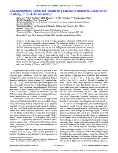
2. Description of apparatus In this research, we developed a low cost fully automated DRI using an Arduino microcontroller, a Hall effect sensor, a peristaltic pump, a water level sensor, and a constant-level float valve that can be used for both constant and falling head systems in both double and single ring infiltrometers. Arduino is a widely used open-source single-board microcontroller development platform that has flexible, easy-to-use hardware and software components (Ferdoush and Li, 2014). In the current set-up, an Arduino is used for interfacing with sensors and as a data-logger. Although Arduino has been applied several times by hydrologists and environmentalists for interfacing with sensors (Hicks et al., 2012; Kruger et al., 2011; Queloz et al., 2013), its application in DRI automation is totally new (Ong et al., 2012; Fatehnia, 2015). Various electrical and mechanical equipment applied in the current design, as depicted in Fig. 1, are explained in this following section.
2.1. Arduino In this set-up, interfacing with the water level sensor, Hall effect sensor, peristaltic pump, and also storing the water flow data in real-time on a micro-SD card was done via the Arduino microcontroller. The Arduino is an open-source hardware platform designed around an 8bit Atmel AVR microcontroller, or a 32-bit Atmel ARM with a clock speed of 16 MHz. Arduino has a USB interface, 14 digital I/O pins (of which 6 can be used as PWM outputs), 6 analog inputs, a 16 MHz ceramic resonator, a power jack, an ICSP header, and a reset button. It contains everything needed to support the microcontroller. The microcontroller can be powered by a laptop with a USB cable or by an AC-toDC adapter or 6–20 V battery. Arduino-compatible custom sensor expansion boards, known as shields, can be developed to directly plug into the standardized pin-headers of the Arduino board. They enable Arduino to connect to several sensors (Ferdoush and Li, 2014; Hut, 2013). The Arduino motor shield was stacked to the Arduino board in order to communicate with the peristaltic pump. The Adafruit motor shield has the TB6612 MOSFET driver with a current capacity of 1.2 A per channel and 3 A peak current. The motor shield was used to drive the peristaltic pump system. It has a fully-dedicated PWM driver chip onboard that handles all the motor and speed controls over I2C. An Arduino data-logging shield was also used to have a real time record of the water flow on a micro-SD card. This eliminated the need for using a laptop computer in the field while the data could be used later for retrieval and could be easily imported into conventional processing and plotting software like Excel. The applied Adafruit data-logging shield has a real time clock (RTC) with a battery backup that keeps the time even when the Arduino is not being supplied with power. It also has an on-board 3.3 v regulator that works as a reference voltage for the microcontroller and AD converters and at the same time, supplies power to activate the SD memory card. 2.2. Peristaltic pump To pump water from the reservoir into the inner ring, a peristaltic pump was used. Peristaltic pumps are a type of positive displacement pumps. They move fluid by using a set of rollers fixed to a motor shaft to force fluids through a flexible tube. This procedure allows precise “metering” of fluid flow through the pump (Hamidi et al., 2013). By counting the number of rotations of the pump roller system it is possible to precisely determine the volume of water passing through the pump. In these pumps, the fluid is contained within a flexible tube fitted inside a circular pump casing. In the casing, a rotor with a number of rollers and shoes attached to the external circumference of the rotor compresses the flexible tube. By each turn of the rotor, the part of the tube under compression is pinched thus forces the fluid to be pumped to move through the tube (Latham, 1966). The pump provides highly accurate, metered volumes of fluid per cycle that is independent of the water supply hydraulic head. 2.3. Hall effect sensor Hall effect sensors can be used for proximity switching, positioning, speed detection, and current sensing applications. To measure the sequential pumped volume of the water that supplied the inner ring and represented the infiltration rate of the soil material, a Hall effect sensor was utilized. A Hall effect sensor is a transducer whose output voltage varies in response to a magnetic field (Ramsden, 2006). Fig. 2 shows the Hall effect sensor used for flow measurement in series with a resistor and attached to the backside of the peristaltic pump. In order to provide the magnetic field variations for sensor performance, two small rare earth magnets were attached to the pump rotor with opposite poles. Readings of the sensor was calibrated in the laboratory by
M. Fatehnia et al. / Geoderma 262 (2016) 133–139
135
Fig. 1. Automated system electronics.
measuring the corresponding volume of the water for each rotation of the pump rotor. 2.4. Water level detector Water level detector was placed in the inner ring to detect the drop of water below a reference level resulting from the infiltration of water
into the soil. Two different methods were employed for detecting the water level of the inner ring. The first method was to use a MOSFET transistor water level sensor as a switch to detect when to turn the pump on and off. The alternative method was to use eTape™ continuous water level sensor (MILONE Technologies). The MOSFET transistor water level sensor sent a high voltage to the Arduino whenever the end electrodes shown in Fig. 3a were in contact with the water. Voltage sending was a low signal whenever the electrodes lost the conductivity of the water due to the water level drop. The eTape™ sensor shown in Fig. 3b was a solid state, continuous (multi-level) fluid level detector that could be applied for level measurement of water or any other non-corrosive water based liquids. Compression of the sensor's envelope due to hydrostatic pressure of the fluid caused a resistance change proportional to the distance from the top of the sensor to the fluid surface which let the sensor to provide a resistive output inversely proportional to the liquid level. 2.5. Constant level float valve The water level in the outer ring, as shown in Fig. 3, was controlled mechanically by using a constant level float valve. Since, during the experiment, there was no need to measure flow of water into the outer ring, the water needed for the outer ring could be supplied using the same elevated water container as the inner ring. 3. System construction and calibration
Fig. 2. Hall effect sensor attached to the peristaltic pump.
The designed automated DRI set-up had a 20 cm diameter inner ring and a 40 cm diameter outer ring with 50 cm heights. An elevated water container supplied the required water for both rings. Since the outer ring water was gravitationally supplied using a float valve, the container needed to be elevated. In the case of using the automated system to run single ring infiltrometer, the peristaltic pump would function even when the water in the container was below the pump level. A constant level float valve was placed at the height of 15 cm above the soil surface within the outer ring. This was used to keep the outer ring water level constant throughout the test. The water level sensor placed in the
136
M. Fatehnia et al. / Geoderma 262 (2016) 133–139
Fig. 3. (a) Water level electrodes for MOSFET transistor & (b) eTape sensor placed in the inner ring.
inner ring was connected to the Arduino Uno. In the case of continuous water level sensor, whenever the inner ring's water level dropped below 9 cm, via Arduino message, the peristaltic pump that supplied water to the inner ring turned on. The pump continued working until the water level reached to 10 cm height. In the MOSFET switch, the pump continued working until the water level electrodes were in contact with the water. The applied RF-100 peristaltic pump had a maximum flow rate of 1000 ml/min and worked with primary power source of 12 V or 24 V brushless DC motor. Since the applied inner ring diameter was 20 cm, the system could be used to run an automated DRI test in soils with maximum infiltration rate values up to 0.05 cm/s. In the case of running the test in granular material with higher infiltration rate values, two peristaltic pumps should be used. The maximum flow rate of the system can be increased to 2000 ml/min by using two similar pumps working in parallel. This can be easily done since the Arduino motor shield can run up to 4 DC motors simultaneously with maximum total power voltage of 24 V. The only changes needed to make while applying two pumps were to replace the motor shield battery with the one that supported the required new voltage and current values. An Arduino code also needed to be updated to handle all connected pumps. Since the three test fields used for analyzing the set-up performance in the current research had maximum infiltration values lower than 0.05 cm/s, the automated set-up with only one peristaltic pump was tested in the field. Communicating of the Arduino with the pump was done via Adafruit motor shield that was stacked to the Arduino Uno. Two 12 V, 5 AH, rechargeable sealed lead acid batteries supplied the power needed for Arduino and the motor shield. The power required for the pump and water level sensor was supplied via the motor shield and Arduino, respectively. More batteries were needed to run the test with 2 pumps. Quantities of the electronic components needed to build the automated system are itemized in Table 1. The diagram in Fig. 4 illustrates the connection arrangement of the pump, sensors, Arduino, and the batteries. In the continuous water level system, a 30 cm eTape™ sensor with a thickness of 0.381 mm and width of 25.4 mm was placed in the inner ring. The sensor had an output range of 400–2000 Ω and resistance gradient of 60 Ω/cm. The sensor resolution was 0.25 mm which resulted an accurate reading of water level changes. However, the readings of the
sensor can be affected by temperature changes. A simple voltage divider with a 6800 Ω reference resistor seated on a prototyping breadboard was used to convert the output of the sensor into voltage, see Fig. 5. Compared to the eTape™ sensor, the MOSFET transistor sensor performance is not prone to drift due to temperature. For this reason, it could provide a more accurate measurement of a specific water level and since it was built by the authors, it had a cheaper final price. On the other hand, unlike the eTape™ continuous water level sensor, it could be only applied to run constant head DRI since it could only detect whether the electrode was in contact with water or not. The circuit applied to run the second system is depicted in Fig. 6.
Table 1 Electronic components used in the design of the automated system. Required equipment
Specifications
Quantity
Arduino Uno Microcontroller
• • • • • •
1
Adafruit motor shield Adafruit data-logging shield
eTape™ continuous fluid level sensor MOSFET transistor circuit Carbon film resistors Metal film resistors RadioShack RS 276–150 Perfboard RF-100 peristaltic pump SP12-5 Sigmas Tek sealed lead–acid battery US1881 Hall effect sensor
Rare earth disk magnets
a
5 V operating voltage 7–12 V recommended input voltage 40 mA DC current per I/O pin Max 25 V DC 0.6 A per bridge (1.2 A peak) Compatible with FAT16 or FAT32 formatted cards • Onboard real time clock (RTC) • 12 in. length
1
• • • •
1 1 1 1
• • • • •
1 KΩ parallel & 1 MΩ series resistors 6800 Ω 220 Ω 2.88 by 1.88 in.
1000 ml/min flow capacity 12 V 1.5 A 3.5 V to 24 V DC operation voltage 50 mA maximum sinking output current • 0.125″ diameter • 0.03125″ ± 0.005″ thickness • 0.954 lbs optimal pull
1 1
1 or 2a 2 or 3a 1 or 2a
2 or 4a
Quantities needed if 2 pumps are used when higher water flow is needed.
M. Fatehnia et al. / Geoderma 262 (2016) 133–139
137
Fig. 4. Connection arrangement of the equipment.
To measure the number of rotations of the peristaltic pump through digital pin of the Arduino using the Hall effect sensor, two small rare earth magnets were attached to the pump rotor with opposite pole directions. The Hall effect sensor was attached to the backside of the Peristaltic pump at 5 mm distance from the magnets. The Hall effect sensor readings were calibrated in the laboratory to detect accurate cumulative volume of water correspond to each number of pump rotor rotations. The Adafruit Data-logging shield, which stacked to Arduino, enabled storing of the flow data on a micro-SD card. The information of the cumulative water flow and time was stored in real-time on a micro-SD card in standard column format.
In the designed system, the test and flow measurements continued until the steady state infiltration rate was reached. This usually happens after 1 to 2 h in most soils (Maheshwari, 1996). The system stops working whenever the infiltration rate changes are less than 10% for an interval of 30 min (Amer, 2011). This is done by comparing the maximum and minimum values of the infiltration rates recorded every second in the last 30 min of the test. The test is terminated whenever the difference is not exceeding 10%. The Arduino code loaded to the Arduino board from computer and stored on it for later use of the system. The set-up with continuous water level sensor could be also applied to run a single ring infiltrometer with falling head method (using only the inner ring). This could be done by simply adopting the code to turn on the pump after full seepage of water and turn it off when the required height was reached. Besides the cost effective final price of the proposed system, it has the following advantages compared to previous proposed automating systems: • Unlike some of the proposed systems, the current system does not require using a laptop computer in the field. In the current set-up, the digital data of the water flow are stored in a real-time on a micro-SD
Fig. 5. Voltage divider of the eTape sensor.
Fig. 6. MOSFET transistor circuit.
138
•
•
•
•
•
•
•
• •
M. Fatehnia et al. / Geoderma 262 (2016) 133–139
card in standard column format and can be used later for retrieval and easy import into conventional processing and plotting software like Excel. The designed set-up can be used for both single ring falling head and double ring constant head DRI by simply adopting the Arduino coding for each method. Since we measure the flow of water that passes through the pump, unlike other methods, a single reservoir can supply the water for both inner and outer rings. Automated pump shut downs when no water needs to be added to the inner ring extend battery life well enough to survive for the test duration. Compared to the complication of adding additional water to Mariotte systems due to their requirement of being “sealed”, water can be easily added to the current system. As the measurements of flow are done using the Hall effect sensor attached to the pump, adding water to the reservoir does not affect the calculations. To provide continuous supply of water to both rings, water can be added to the reservoir, whenever its level drops, without a need of correcting the measurements. Using the Hall effect sensor and counting the number of pump rotations to measure the flow of water also has the benefit of constant measurements in different temperatures. Unlike some other methods that require precautions and calibrations for temperature or sunlight effect, measurements of this set-up is not a factor of temperature or barometric pressure. Using the Hall effect sensor also enables precise measurements of low infiltration values. Since any rotation of pump corresponds to specific volume of water, even small volumes can be detected and measured at high precision by the sensors. The system can detect when the steady state infiltration has happened. This way, the test automatically stops and concludes data recording. This system can easily be stored in a waterproof, ruggedized storage container. This is very desirable for remote data logging in an outdoor environment.
4. System testing and results In order to check the accuracy of the automated system, three sets of tests were conducted at different locations with different soil materials. For comparison purposes, at each test location, a manual and an automated DRI test were performed. In each location, we ran the automated and manual tests with enough of a separation distance to avoid interference of the wet fronts. The DRI field experiments, as shown in Fig. 7, had 20 cm inner and 40 cm outer ring diameters with ring depths of 10 cm. The measured steady state infiltration rates and initial infiltration values for both methods were measured afterwards using the recorded results of the flow. The values were compared for each set of tests. These data are plotted in Table 2. The automatic test results showed no irregularity in the infiltration from the pump response. After each experiment, granulometric analyses were performed on the field soil samples according to ASTM D 422-02 (ASTM, 2007). The first testing location was the FSU Reservation area in Tallahassee, Florida. The light brown sand of the test site could be described as well-sorted, fine to coarse sand. It was categorized as SW based on Unified, and A-3 in AASHTO soil classification systems. The test site had a gently sloping surface (2–4°). A nearly constant infiltration rate over the 40–60 minute test run was produced by relatively high permeability of this soil. Graphs of cumulative infiltration rate versus time for automated and manual tests performed in this location are provided in Fig. 8. The second test location was in the vicinity of Tallahassee regional airport area. The surface soil material included mottled dark and light brown medium to fine sand that was classified as SP-SM based on Unified and A-3 in AASHTO soil classification systems. The test site
Fig. 7. Field DRI test applying the automated system.
had a gentle slope of 3–5°. The last set of tests were conducted in Greenway, Tallahassee area. The surface material was mottled light brown and reddish brown or light gray clayey fine sand that classified as SC in unified and A-2-4 in AASHTO soil classification systems. Soil surface had a 2–4° slope. By comparing the information of the manual and automatic DRI experiments provided in Table 2, acceptable performance of the automated system is revealed. The obvious advantage of the system is that it can accurately detect when the steady state infiltration rate has reached. 5. Conclusion The double-ring infiltrometers are widely used for in situ measurement of field saturated hydraulic conductivity. In this paper, an automated double ring infiltrometer was developed by using a peristaltic pump, a water level sensor and a microcontroller. The system automatically runs the test, concludes the process when steady state is reached, and records the infiltration data on a micro-SD card. The system was mounted in a portable and weather resistant box that can be easily used in the field. The overall system architecture, and the design of Table 2 Comparison of the automated and manual DRI experiments. Test location
Test format
Maximum infiltration rate (cm/s)
Steady infiltration rate (cm/s)
Florida State University Reservation Tallahassee regional airport Greenway, Tallahassee
Automated system Manual testing Automated system Manual testing Automated system Manual testing
3.35 × 10⁻² 3.50 × 10⁻² 6.63 × 10⁻³ 6.50 × 10⁻³ 1.93 × 10⁻³ 1.70 × 10⁻³
1.93 × 10⁻² 1.85 × 10⁻² 4.33 × 10⁻³ 4.60 × 10⁻³ 1.42 × 10⁻³ 1.20 × 10⁻³
M. Fatehnia et al. / Geoderma 262 (2016) 133–139
139
Fig. 8. Location 1 Automated and Manual DRI test results.
hardware and software components were presented in detail and the advantages of the developed system compared to the other methods were described. To check the workability of the proposed system, three field DRI tests with automated system together with manual experiments were conducted. By comparing the results of the field DRI testing using the automated set-up with the manual experiments in all three test sites, an acceptable precision of the automated system in infiltration measurement was revealed. Appendix A. Supplementary data Supplementary data to this article can be found online at http://dx. doi.org/10.1016/j.geoderma.2015.08.022. References Ahuja, L.R., 1976. Measuring hydrologic properties of soil with a double ring infiltrometer and multiple depth tensiometers. Soil Sci. Soc. Am. J. 40, 494–499. Amer, A.M., 2011. Prediction of hydraulic conductivity and sorptivity in soils at steady state infiltration. Arch. Agron. Soil Sci. 58, 1179–1194. http://dx.doi.org/10.1080/ 03650340.2011.572877. Ankeny, M.D., Kaspar, T.C., Horton, R., 1988. Design for an automated tension infiltrometer. Soil Sci. Soc. Am. J. 52, 893–896. Arriaga, F.J., Kornecki, T.S., Balkcom, K.S., Raper, R.L., 2010. A method for automating data collection from a double-ring infiltrometer under falling head conditions. Soil Use Manag. 61–67 (March 26). ASTM Standard D3385-09, 2009. Standard Test Method for Infiltration Rate of Soils in Field Using Double-ring Infiltrometer West Conshohocken, PA, http://dx.doi.org/10. 1520/D3385-09 (www.astm.org). ASTM Standard D422-63(2007)e2, 2007. Standard Test Method for Particle-size Analysis of Soils West Conshohocken, PA, http://dx.doi.org/10.1520/D0422-63R07E02 (www. astm.org). Bouwer, H., 1986. Intake rate: cylinder infiltrometer. In: Klute, A. (Ed.), Methods of Soil Analysis. Part 1, 2nd ed. Agron. Monogr. 9. ASA. and SSSA, Madison, WI, pp. 825–844. Constantz, J., Murphy, F., 1987. An automated technique for flow measurements from a Mariotte reservoirs. Soil Sci. Soc. Am. J. 51, 252–254. Fatehnia, M., 2015. Automated Method for Determining Infiltration Rate in Soils (Electronic Theses, Treatises and Dissertations, Paper 9327) . Fatehnia, M., Tawfiq, K., 2014. Deriving vertical saturated hydraulic conductivity of soil using double ring infiltrometer infiltration information. 7th International Conference on Environmental Science and Technology, Houston, Texas, June 9–13 vol. 2, pp. 224–230. Fatehnia, M., Tawfiq, K., Abichou, T., 2014. Comparison of the methods of hydraulic conductivity estimation from mini disk infiltrometer. Electron. J. Geotech. Eng. 19 (E), 1047–1063.
Ferdoush, S., Li, X., 2014. Wireless sensor network system design using raspberry Pi and Arduino for environmental monitoring applications. The 9th International Conference on Future Networks and Communications (FNC'2014)/The 11th International Conference on Mobile Systems and Pervasive Computing (MobiSPC'14), Ontario, Canada, August 17–20 vol. 34, pp. 103–110. Gregory, J.H., Dukes, M.D., Miller, G.L., Jones, P.H., 2005. Analysis of double-ring infiltration techniques and development of a simple automatic water delivery system. Appl. Turfgrass Sci. 2 (1), 1–7. Hamidi, A., Habibagahi, G., Ajdari, M., 2013. A modified osmotic direct shear apparatus for testing unsaturated soils. Geotech. Test. J. 36 (1), 1–10. Hicks, S., Aufdenkampe, A.K., Montgomery, D.S., 2012. Creative uses of custom electronics for environmental monitoring. American Geophysical Union Annual Fall Meeting, San Francisco, California, December 3–7. Hut, R., 2013. New Observational Tools and Data Sources for Hydrology: Hydrological Data Unlocked by Tinkering (Master thesis) Delft University of Technology, Amsterdam, Netherlands. Kruger, A., Niemeier, J.J., Ceynar, D.L., 2011. The drifter platform for measurements in small rivers. American Geophysical Union Annual Fall Meeting, San Francisco, California, December 5–9. Lai, J., Luo, Y., Ren, L., 2010. Buffer index effects on hydraulic conductivity measurements using numerical simulations of double-ring infiltration. Soil Sci. Soc. Am. J. 74 (5), 1526–1536. Latham, T.W., 1966. Fluid Motion in a Peristaltic Pump (M.Sc. Thesis) MIT, Cambridge, Massachusetts. Lazarovitch, N., Ben-Gal, A., Šimůnek, J., Shani, U., 2007. Uniqueness of soil hydraulic parameters determined by a combined wooding inverse approach. Soil Sci. Soc. Am. J. 71, 860–865. http://dx.doi.org/10.2136/sssaj2005.0420. Maheshwari, B.L., 1996. Development of an automated double-ring infiltrometers. Aust. J. Soil Res. 34, 709–714. Matula, S., Dirksen, C., 1989. Automated regulating and recording system for cylinder infiltrometer. Soil Sci. Soc. Am. J. 53, 299–302. Milla, K., Kish, S., 2006. A low-cost microprocessor and infrared sensor system for automating water infiltration measurements. Comput. Electron. Agric. 53, 122–129. Ong, J., Werkema, D., Lane, J.J.W., 2012. Revisiting the fully automated double ring infiltrometer using open-source electronics. AGU Fall Meeting Abstracts. Prieksat, M.A., Ankeny, M.D., Kaspar, T.C., 1992. Design for an automated, self-regulating, single-ring infiltrometer. Soil Sci. Soc. Am. J. 56, 1409–1411. Queloz, P., Besuchet, J., Rao, P.S.C., Rinaldo, A., 2013. Development of a low-cost wireless controller for flexible sampling strategies based on real-time flow monitoring. EGU General Assembly Conference, Vienna, Austria, April 7–12. Ramsden, E., 2006. Hall-effect Sensors: Theory and Applications. 2 ed. Elsevier, Burlington, MA 0-7506-7934-4. Swartzendruber, D., Olsen, T.C., 1961. Model study of the double ring infiltrometers as affected by depth of wetting and particle size. J. Soil Sci. 92 (4), 219–255. Youngs, E.G., 1987. Estimating hydraulic conductivity values from ring infiltrometer measurements. J. Soil Sci. 38 (4), 623–632.