Automating Integration of Heterogeneous COTS Components Wenpin Jiao, Hong Mei Institute of Software, School of Electronics Engineering and Computer Science Peking University, Beijing 100871, China
[email protected],
[email protected]
Abstract. Mismatches make COTS components difficult to be incorporated. In this paper, an approach is presented to eliminate mismatches among COTS components, which can truly consider COTS components as black boxes. In the approach, only the assembly description of components is required, based on which adaptors for resolving mismatches can be generated automatically. This paper also described an agent-based GUI implementation of the approach.
1 Introduction Appropriate use of commercial-off-the-shelf products (i.e., COTS) is one of the remedies that might enable developers to acquire needed capabilities in a cost effective manner, and easy usage of COTS to interoperate properly within applications is crucial for component-based software systems. Currently, many existing commercial component-oriented platforms address the interoperability of component-based software by using Interface Description Languages (IDL). However, in component composition using a specific configuration, mismatches may occur when the assumptions that a component makes about other components, or the rest of the system, do not match [16]. Even if the functionalities of components are matched and signature problems are overcome, the components are not assured of interoperating suitably. First, at the component level, because of the ordering of exchanged messages and of blocking conditions [19], the mismatching interaction protocols may result in different behaviors of components. For instance, the order of messages exchanged and the sizes of data blocks transmitted between components may be different. Second, at the architecture level, components at hand are usually supposed to support specified architectural styles and they may not interoperate properly in software systems with constraints of other architectural styles [8][15]. For example, components to be integrated based on method invocation may not be suitable to be directly integrated into software systems using the event-based architectural style. Third, at the application domain level, COTS components are often involved in different naming spaces and the names for the same data entities may be discrepant. Ideally, for integrating heterogeneous COTS components, approaches should at least satisfy the following requirements.
•
Resolve naming and structuring discrepancies among interoperating components due to different ontologies of application domains; • Enable components specific to different architectural styles to interact; and • Incorporate components with mismatching interaction protocols. In this paper, we adopt an agent-based approach to integrating heterogeneous COTS components. The main contributions of the paper are as follows. We put forward an approach to incorporating COTS components with mismatches at different levels. Our approach neither limits the number of incorporating COTS components nor requires knowing any detailed information about what interaction protocols COTS components are supposed to support so that COTS components can truly be considered as black boxes in integrations. Second, we describe an automated way to generate adaptors for resolving mismatches at interaction protocol level. By using the generated adaptors, data block mismatches and message-ordering mismatches can be eliminated automatically if components are incorporable. Third, we present an agent-based implementation of the approach, in which agents can resolve the architectural style mismatches via transforming style specific interactions into uniform ACL (agent communication language) based communications and can automatically remove deadlocks potentially occurring in the interactions of COTS components even if components are not incorporable. In the following context, Section 2 discusses the incorporability of COTS components and describes methods for eliminating mismatches involved in different levels. Section 3 and 4 describes the agent-based approach and its implementation, respectively. Section 5 discusses some related work and concludes our work.
2 Elimination of Mismatches In our opinions, the premise that components can interact is that names can properly be mapped between input data and output data and interactions can be transformed from one architectural style specific to another style specific. Definition 1. Incorporability. Components are incorporable if they satisfy the following conditions. 1. There is a name mapping, in which all input data entities (including their internal ingredient) imported by components are imaged (mapped) to output data entities exported by other components. 2. All style specific interactions can be transformed between different styles. 3. After names are properly translated and style specific interactions are well transformed, the components are compatible at the protocol level. Nevertheless, it is very difficult to obtain the semantics of names and infer the mapping between names automatically even though there have been some ontology tools to specify names formally (e.g., [17]). In addition, COTS components are usually only documented with the usage syntax of their interfaces when they are released, whereas architectural styles that COTS components are supposed to support are generally not specified explicitly.
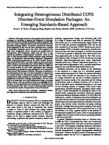
Therefore, in this paper, we put forward the notation of assembly for specifying the interconnections of components, which describes the name mapping that components use to transmit data along interconnection links, the architectural styles that components support, and the intentions that components set up the interconnections. By using the specifications of assemblies among components, we can implement an automated approach to resolving name conflicts and transforming mismatching architectural interactions. 2.1 Assembly Description of Components In general, people know little about the interaction protocols of COTS components. To provide a generic solution for incorporating COTS components, we will not make additional assumptions about the information exposed by COTS components. To describe the assembly of COTS components, we should first know what COTS components participate in the assembly. For example, an assembly involving a component playing the role of user and another component implementing the server can be described as follows. Then we need (and just need) know how COTS components are interconnected. In our opinions, connections among components are links for transporting data for different purposes, for instance, requesting services or calling methods. We assume that each connection is only used for unilateral data transportation. For each connection, there involve at least one source component and just one destination component and there is an intention (or purpose) of establishing the connection. In the establishment of a connection, the architectural style to which the source component is specific may be different from that of the destination component. For example, the user sends a message containing “username”, “email” and “password” to authenticate itself to the server. Meanwhile, the server calls procedure “authUsr(usr, pwd)” to authenticate the legality of the user and returns “yes” for successful authentication or else the reason for failed authentication (fig. 1). username, email, password usr, pwd User
yes | reason
Server
result
Fig. 1. Assembly of Components
In the assembly, there are two connections, one transports {“username”, “email”, “password”} for calling “authUsr(usr, pwd)” and the other returns the authentication result. In the figure, arrows represent data links through which upside data block is sent from the end to the head whilst the underside is being expected at the head. The
connections between the two components can be described in the XML as follows. C_ID1 C1 message-based C2 procedure-call authUsr(usr, pwd) Each connection has a unique identity. Within a connection, there is more than one source section. Each source section is related to a component and describes the data block(s) exported by the component. Differently, there is only one destination section that specifies the data block(s) imported to a destination component. In each source or destination section, the architectural style used to export or import the data block(s) is also required to be specified. The intention section specifies what action the destination component will take after it receives the data exported by the source component(s). The intention can be specified via directly referencing a signature defined in the component’s interface, for instance, “authUsr(usr, pwd)”. The mapping section specifies how exported data items will be used as imported data items. In principle, for all expected (i.e., imported) data, there should exist the corresponding data exported from the sources (or else default values should be offered). Contrarily, for an exported data, it may not be expected by the destination so there may not exist a corresponding imported data. 2.2 Compatibility of Components As mentioned above, two components are considered to be interoperable if they are compatible after naming discrepancies and architectural style mismatches have been resolved. Furthermore, we say components are compatible if the executions of all
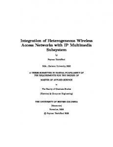
input actions occurring in the interactions are guaranteed, i.e., components can obtain all of the required data (or arguments) before they provide services and can gain the results after they request services. We can specify the interactions among components by using directed graphs, in which actions are nodes and arcs represent orders of actions. For any action, arcs fanning out from it will fan into other actions that should (or will) take place after it. According to the graph theory, we can prove that components are compatible if there is at least one action without fan-in arcs whenever actions happen in the interactions among the components. In our definition, we do not restrict the incorporability to be related to only two components. In addition, we assume that components are distributed on different sites and there are no troubles with sharing resources. Therefore, the occurrences of deadlocks are merely due to interactions instead of resource contention. Theorem 1. If components are incorporable, there must exist an additional component (e.g., adaptor) that can incorporate the components together, i.e., the adaptor can eliminate the data block mismatches and interaction protocol mismatches occurring in the interactions of the components. We will not prove the theorem due to the space limitation. Anywhere, adaptors can automatically be generated for incorporating components. Assume that naming conflicts and architectural style mismatches have been resolved by using the assembly specifications. Then the main tasks of the adaptor for incorporating two components include 1) resolving data block mismatches and 2) removing deadlocks occurring in the interactions. To resolve the data block mismatches, we adopts a strategy by which the adaptor disassembles intercepted data blocks exported from source components into atomic data items (i.e., the atomic ingredients of the data block) and re-assembles related atomic data items into expected data blocks imported by destination components. To remove the deadlocks caused by synchronizations, we adopt a strategy using the message buffer that can be accessed randomly and concurrently. Suppose the name mapping among components P1, …, Pn, is M. Then, the adaptor can be divided into three parts. 1. Disassembler. Intercept data exported by components, disassemble it into atomic ingredients, and then rename them, for instance, d to M(d). 2. Buffer. Buffer the intercepted and disassembled data on one hand and then wait for the Assembler to take away the data. 3. Assembler. Transfer the buffered data to components that are importing data. To meet a component’s expectation for data, the adaptor first obtains data ingredients from the buffer, then assembles them into the expected data block and at last transmits the block to the component. The adaptor is actually defined as a composition of parallel finite automatons (FA). Corresponding to every export action occurring in the assembly, there is an FA generated, in which steps are states and actions are labels causing the interaction transiting from one step to another step. For example, there are two components P={-(a), +(b), -(c)} and Q={-(b), +(a, c)}, in which +/- represents data input/output (fig. 2a). Obviously, there is a data block
mismatch and a deadlock between P and Q if the collaborative input/output actions should be synchronized. The adaptor will be generated for incorporating the two components as shown in fig. 2b. P
Q Step 1
P
-(a) Step 2 +(b) Step 3 -(c) Step 4
Step 1
Step 3
-(a) -(b) Step 2
Step 2 +(b)
+(a, c) Step 3
Order relation of steps within components
+(a) Step 2
Step 3 -(c)
-(a)
+(c) Step 4 -(c)
Step 5 +(a) Step 6 +(c) Step 7
Step 8 +(b) Step 9 -(b)
Step 1 -(b) Step 2 +(a, c)
-(a, c)
Step 4
2.a. Interaction with mismatches Legend:
Q
Adaptor Step 1
Step 1
Step 1
Step 3
Step 5
Step 8
Step 3
2.b. Adaptor for resolving interaction mismatches Synchronization relation of steps between components
Fig. 2. Resolving Protocol Mismatches
According to the above description, for any export action occurring in the assembly, there must be a collaborative import action in the adaptor to accept the data coming from the source component and transmit the data into the buffer implemented in the adaptor. On the other hand, for any imported data block, if its ingredients have been buffered in the adaptor when the corresponding import action is going to fetch the data block, the import action will not be blocked. Therefore, if components involved in the assembly are incorporable they will be able to be incorporated properly via the adaptor. As shown in the above example, because there is always at least one export action taking place during the interactions between P and Q, the deadlock is removable by using the adaptor (fig. 2b). However, when components are not incorporable, deadlocks will be irremovable by just using the generated adaptors. For example, suppose P={+(a), -(b)} and Q={+(b), -(a)}, there is a deadlock between P and Q and the adaptor cannot remove it because all finite automatons in the adaptor begin with import actions, too. To remedy this limitation, we will discuss how to implement agents to discover and remove deadlocks in the next section besides describing how to use agents to incorporate components.
3 Incorporation Using Agents To resolve the mismatches between COTS components, we need adequate semantic information about components and their interactions so that we could transform style specific interactions (SSI) into homogeneous communications and could use name mappings for generating adaptors automatically. Therefore, we adopt an agent-based approach to implementing adaptors to incorporate COTS components. In a distributed computing environment, it will be unacceptable to implement centralized adaptors to incorporate COTS components. A reasonable way is to resolve the mismatches locally and then interconnect COTS components together.
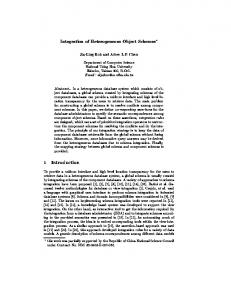
In our approach, the adaptor to incorporate components is partitioned into parts and each part is locally attached to a component and takes charge of the component’s interactions. The responsibilities of the part at component P’s side include: 1. Disassemble data blocks coming from P and send them out. 2. Buffer data received from other components. 3. Assemble data ingredients into expected blocks and forward them to P. The architecture by using agents to implement adaptors and incorporate distributed COTS components can be depicted as follows (fig. 3), in which agents are locally attached to the COTSs at the same sides. Agent
Agent
Interceptor
Interceptor Adaptor
COTS
SSI Assembly Spec
Legend:
Adaptor
Xformer
ACL
Style-specific Interaction
Xformer Disassembler Assembler
Buffer Buffer
ACL-based Communication
Assembler Disassembler
Specification Information
COTS
SSI ACL
Assembly Spec
Bidirectional Transformation
Fig. 3. Architecture for Incorporation of COTS
The interceptors are responsible for 1) intercepting style specific interactions of components, transforming into ACL messages and forwarding to the adaptors, and inversely 2) receiving ACL messages from other agents, transforming into style specific interactions and interacting with the components. In addition, the interceptors are also in charge of 3) obtaining the specifications of the assembly, including the architectural styles and name mappings, and providing the agents for generating the adaptors automatically. The adaptors take charges of taking actions specified in the finite automatons, which has been transformed into ACL-based communications. As most agents do, our agents also use the FIPA ACL [14] as the agent communication language. In general, most of interactions among COTS components are to transport the values of variables. “inform-ref” and “forward” are two of the most frequently used performatives. “inform-ref” indicates a macro-action for the sender to inform the receiver the value that corresponds to a referential expression; whilst “forward” is used for the sender to ask the receiver to forward a message to another agent. For example, an action involved in a connection is to send data block d from P to Q, then the ACL message corresponding to the action can be expressed as follows. (inform-ref :sender P :receiver Q :content (Connection-Identity, d, value of d)) For convenience, we name the interceptor and the adaptor at P’s side as interceptorP and adaptorP, respectively. For transforming architectural style-specific interactions and executing the adaptors, the agents will generate and trigger corresponding rules according to the specification of the assembly.
3.1 Transforming Style-specific Interaction To guarantee the transformation automated, we assume that any exported data is sent out for a unique intention. Thus, whenever an interceptor captures data out from a source component according to the architectural style supported by the source component, it can definitely make out where the data will be transmitted and what the component intents to do. To transform bi-directionally between style-specific interactions and ACL based communications, interceptors use a group of rules. When an interceptor locating at the source component side captures an exported data block from the component, it will trigger the following transformation rule. Export action perceived → { 1. Extract the data block transported by the export action; 2. Retrieve the data block in the assembly specification and locate the connection in which the export action is involved; 3. Compose an ACL message to forward the data block to the destination component via the adaptor.} For example, suppose interceptorP perceives an export action of P, which is involved in connection C and is sending data D to Q. The corresponding ACL message is constructed as follows. (Forward :sender interceptorP :to adaptorQ :receiver adaptorP :content ) When an interceptor locating at the destination component side receives an ACL message from the adaptor, it will trigger the following transformation rule. ACL message received → { 1. Extract the data block and the connection identity transmitted along with the ACL message; 2. Obtain the intention of the connection via looking up the assembly specification; 3. Take actions to realize the intention by using the received data according to the architectural style supported by the destination component.} For example, suppose the intention is to call a procedure using the received data as arguments. Then the interceptor will make an invocation of the procedure. 3.2 Executing Adaptors Since adaptors are composed of a group of parallel finite automatons, we implement adaptors using multiple threads, in which each FA is executed via a thread and controlled by a group of rules. For an FA disassembling data, the corresponding thread uses the following rule. ACL message from an interceptor received → { 1. Extract the data block transported along with
the message; 2. Disassemble the data block into ingredients and rename them according to the name mapping specified in the connection; 3. Package every ingredient into an ACL messages and send it out sequentially.} For example, when adaptorP receives the above message, it will first disassemble D and then transmit D’s ingredients to adaptorQ sequentially. (Forward :sender adaptorP :to interceptorQ :receiver adaptorQ :content ) For an FA assembling data, the corresponding thread uses the following rules. D’s ingredient is buffered in the adaptor’s buffer → { 1. Extract the ingredient from the ACL message.} All of D’s ingredients are obtained → { 1. Assemble the ingredients; 2. Generate an ACL message containing the data block and send it to the interceptor.} For example, when adaptorQ receives a data block, it will generate the following message. (Inform-ref :sender adaptorQ :receiver interceptorQ :content ) For the FA buffering ingredients, the adaptor will also implement an independent thread to receive ACL messages and store them temporarily in a message buffer. 3.3 Removing Deadlocks As we have mentioned that adaptors cannot remove all kinds of deadlocks. Therefore, we had to seek help from agents. Since all FAs in adaptors begin with import actions, the interactions among components run into deadlocks must be because all actions currently occurring among components are import actions, too. Therefore, once agents find that they do not receive any messages for a while in the following situations, they can assert that there may be deadlocks occurring in the interactions. 1. An adaptor is blocked during accepting data ingredients in an FA assembling data block. 2. For some connection, the adaptors have not ever received any related data. In both cases, the source components may be blocked so it cannot provide data for the destination component smoothly. In principle, a source component is blocked must be because it is also a destination component involved in another connection. Therefore, to break a deadlock (in fact, a waiting cycle), we need only let a component involved in the deadlock obtain what it is waiting for to force the component to get out from the waiting cycle. To achieve this, the agents will simulate source components to generate blank data blocks so that some destination component would not be stalled.
4 Implementation of the Agent-based Approach To make the description of the implementation more easily understandable, we first describe an application system as follows. The system is designated to manage the dormitory information of students. When a new student is enrolled, the system should allot an accommodation to the newcomer, and while a student leaves, the system should de-allot the accommodation. In the system, there are two tables involved: one records the information about students and the other about the dormitories. These two tables are associated as follows (fig. 4). Student Name Student-ID Gender Date of Birth Department Grade
Reside in Resident Student-ID Building Room
Dormitory Building Room Address Postal Code
Fig. 4. Association between Students and Dormitories
There are four distributed COTS components available for constructing the system: • A general-purpose table editor. The editor is an executable program that implements a GUI to edit relational data tables, including inserting new and deleting old records. The usage of the editor is specified as follows. EDITOR •
A general-purpose table manipulator. It is implemented as a procedure and can be called to update relational data tables, including inserting new and deleting old records. The signature of the manipulator is specified as follows: void MANIPULATOR(String table_name, String record_value, Integer operation);
•
record_value contains the values of all fields of a record of the table, in which each field is a fixed length of string. operation indicates what manipulation the procedure will do, for example, updating, inserting, or deleting a record. A domain-specific procedure for allotting the dormitory to a newcome student according to the newcomer’s gender, department, and grade. The dormitory information consists of the building and the room number. void ALLOTTER(String student_id, Integer gender, String department, Integer grade,String *building_no, String *room_no);
•
A domain-specific console. The console browses information about students and their accommodations and calls Editor to edit students’ information. In the system, there are four interconnection links among these components: 1. Console calls Editor to enroll (or de-enroll) students. 2. When Editor inserts a record into Student table (a student is enrolled), Allotter will be triggered to allot an accommodation to the student.
3.
After Allotter finishes the computation of allotting the accommodation, Manipulator will be called to insert a record into Resident table to store the accommodation information. 4. When Editor deletes a record (a student leaves), Manipulator will be triggered to remove the related accommodation from Resident table. Among these connections, interaction 1 and 3 are procedure-call based while connection 2 and 4 are event-based and the architectural styles supported by the interactions are mismatched with the styles supposed by the COTS components. For implementing the system via integrating COTS components, we developed a GUI (fig. 5) in the Java on the Borland JBuildertm platform to draw the assembly and generate the XML-based assembly specification. The GUI will also generate source codes for agent-based adaptors automatically. An adaptor is instantiated from an agent framework conformed to the FIPA specification [14], which integrates a rule engine for Java platform, Drools [9], using the Rete [13] algorithm to process rules.
Fig. 5. GUI of the COTS Integration Environment
After the assembly is specified, the resource codes of agent-based adaptors can be generated automatically. For each connection, two agents are generated and reside separately beside the two connected components. For each agent, it will intercept interactions of its host component and resolve the mismatches of interactions. For example, in the connection between Allotter and Manipulator (i.e., the A-M conn), Allotter will call Manipulator after it finishes the computation of allotting the accommodation. Because Allotter will offer data items such as table name, student id, building number and room number separately, which are different from the parameters required by Manipulator, when it tries to call Manipulator, Manipulator syntactically cannot be called. By using the intentions and the data item mappings specified in the connection specification, the GUI can generate agents for eliminating mismatching interactions between Allotter and Manipulator. For example, the GUI will generate the code segments for the agent locating at the side of Manipulator as follows, in which each segment may correspond to a behavior rule of the agent. 1. Define a collection of Boolean variables corresponding to those expected data
2.
items. For example, if Manipulator is waiting for the table name, define table_name_received to record the state of the receival of the table name. Initialize these Boolean variables. Initially, these variables are assigned with false. However, if an expected data item is provided with a default value in the name mapping section in the assembly specification, assign the corresponding Boolean variable with true. table_name_received = false; student_id_received = false; building_no_received = false; room_no_received = false; operation_received = true;
3.
Wait for data items from Allotter. The agent will frequently poll the buffer to find out whether an expected data item arrives. Once the agent receives a data item, it will mark the data item to indicate that the data item has been received. For example, when the agent finds that an ACL message in the buffer contains the table name, it will execute the following statements. msg = getACLMessage(); if (msg.sender = “allotter”) { item_name = msg.getDataItemName(); if (item_name = “resident_table_name”) { table_name_received=true; resident_table_name=msg.getDataItemValue();}}
4.
Assemble data items into data blocks according to the name mapping if all data items received, and then call Manipulator based on the procedure-call style. In this code segment, operation is assigned with 1 by the GUI automatically though Allotter does not send any value of operation out. if (table_name_received && student_id_received && building_no_received && room_no_received && operation_received) { table_name = resident_table_name; record_value = student_id+building_no+room_no; operation = 1; manipulator(table_name, record_value, operation);}
After the agents are generated, they will behave as follows. 1. When Console tries to call Editor to enroll or de-enroll students, the agent residing beside Editor will capture the calling and fork a new process to execute Editor. 2. When Editor inserts a new student record into Student table, Console will dispatch an event out to notify that a new student is enrolled. When the agent along with Allotter captures the event, it will first call Allotter to allot an accommodation for the student and then call Manipulator to store the accommodation information into Resident table. 3. When Editor deletes a student record from Student table, Console will dispatch an event out to notify that a student leaves. And then, when the agent along with Manipulator captures the event, it will call Manipulator to remove the related accommodation information from Resident table.
5 Related Work and Conclusions To eliminate mismatches among COTS components, people usually implement wrappers or adaptors while integrating them [12]. For instance, [4] and [10] explore means of implementing connectors to wrap and integrate components. [2] defines connectors as glue to connect components. [19] formally introduced the notion of adaptor as a software entity capable of letting two components with mismatching behaviors interoperate. In [5], a methodology is defined for the automatic development of adaptors. In [6], an adapter is presented to isolate, encapsulate, and manage a component's interactions outside the component. Meanwhile, some formal approaches are presented for detecting interaction mismatches [7][15], and some techniques are proposed for dealing with architectural mismatches by means of analysis [8], removal [12] and tolerating [18]. In [3], an architectural approach is described for detection and recovery of incompatible interactions by synthesizing a suitable coordinator. In addition, [11] presents an integration framework for adding notification and data synchronization facilities to COTS tools so that they can be integrated as active software components. However, existing work is usually focused on behavior mismatches at the component level, whilst some coping with architectural level mismatches are mainly concerned with those special architectural constraints, called conceptual features [1]. Moreover, many approaches mainly discussed how two COTS components could be incorporated or one COTS component could be integrated into a system. In this paper, we presented a very simple approach to incorporating COTS components with mismatches at different levels. To incorporate COTS components, we need only ask to provide the assembly description of COTS components, which specifies what interaction connections exist among components and why components build those connections. Based on the assembly specification, adaptors for resolving mismatches among components can be generated automatically. Nevertheless, in our approach there are still limitations to be overcome in our future work. First, we have assumed that every exported data was created for only one intention in an assembly. Second, our approach will generate two agents for each connection. When the number of connections becomes larger, the scalability of the system may be affected because of a large number of agents generated. At the next stage, we will conduct more experiments to examine and improve the scalability of our approach. Third, the transformations between style specific interactions and ACL messages are ad hoc implemented in agents. In the future, we will explore how to build the ontology of software architecture so that agents can make transformations automatically based on the understanding to the ontology.
Acknowledgements This work is partially sponsored by the National Basic Research Program of China
(973) (Grant No. 2002CB312003), the National Natural Science Foundation of China (Grant No. 60233010, 60303004, and 90412011), and the National High-Tech Research and Development Program of China (863) (Grant No.2005AA112030).
References 1. Abd-Allah, A. Composing Heterogeneous Software Architectures, Doctoral Dissertation, Center for Software Engineering, University of Southern California (1996) 2. Allen, R., Douence, R., and Garlan, D. Specifying and Analyzing Dynamic Software Architectures. In Proceedings of 1998 Conference on Fundamental Approach to Software Engineering, LNCS 1382 (1998) 21-37 3. Autili, M., Inverardi, P., Tivoli, M. and Garlan, D. Synthesis of “correct” adaptors for protocol enhancement in component-based systems. Proceedings of SAVCBS’04 Workshop at ESEC/FSE (2004) 4. Balzer, R. and Goldman, N. Mediating Connectors. Proceedings of the 19th IEEE International Conference on Distributed Computing Systems (1999) 73-77 5. Bracciali, A., Brogi, A., and Canal, C. Systematic component adaptation. Electronic Notes in Theoretical Computer Science, 66(4) (2002) 6. Chiang, C.C. The use of adapters to support interoperability of components for reusability. Information and Software Technology, Vol.45, No.3 (2003) 149-156(8) 7. Compare, D., Inverardi, P., and Wolf, A. L. Uncovering architectural mismatch in component behavior. Science of Computer Programming, 33(2) (1999) 101–131 8. Davis, L., Gamble, R.F., Payton, J. The impact of component architectures on interoperability. Journal of Systems and Software 61(11) (2002) 31-45 9. Drools. http://drools.org/. 10. Ducasse, S. and Richner, T. Executable connectors: Towards reusable design elements. In ACM Foundations of Software Engineering, LNCS 1301. Springer (1997) 483–500 11. Egyed, A. and Balzer, R. Integrating COTS Software into Systems through Instrumentation and Reasoning. Automated Software Engineering, Vol.13, No.1 (2006) 41-64 12. Egyed, A., Medvidovic, N., and Gacek, C. Component-based perspective on software mismatch detection and resolution. IEE Proc.-Softw., 147(6) (2000) 225-236 13. Forgy, C.L. Rete: A Fast Algorithm for the Many Pattern/ Many Object Pattern Match Problem, Artificial Intelligence 19 (1982) 17-37 14. Foundation for Intelligent Physical Agents, http://www.fipa.org. 15. Gacek, C. Detecting Architectural Mismatches During Systems Composition---An Extension to the AAA Model. Technical Report USC/CSE-97-TR-502, Center for Software Engineering, University of Southern California (1997) 16. Garlan, D., Allen, R., and Ockerbloom, J. Architectural mismatch: Why reuse is so hard. IEEE Software, 12(6) (1995) 17–26 17. Gruber, T.R. A Translation Approach to Portable Ontologies, Knowledge Acquisition, vol. 5, no. 2 (1993) 199–220 18. de Lemos, R., Gacek, C. and Romanovsky, A. Tolerating Architectural Mismatches. In: de Lemos, R., Gacek, C. and Romanovsky, A. (eds.), Architecting Dependable Systems, LNCS 2677, Springer-Verlag, Berlin (2003) 175-194 19. Yellin, D. M. and Strom, R. E. Protocol specifications and components adaptors. ACM Trans. on Programming Languages and Systems, 19(2) (1997) 292–333