International Journal of Software Engineering and Its Applications Vol.7, No.5 (2013), pp.167-196 http://dx.doi.org/10.14257/ijseia.2013.7.5.17
Automating Software Development Process: Analysis-PIMs to Design-PIM Model Transformation Brahim Bousetta*, Omar El Beggar and Taoufiq Gadi Lab. LAVETE, Faculty of Science and technologies of Settat Hassan 1st University, Morocco *E-mail:
[email protected] Abstract A software development process describes a structured set of activities or tasks that must performed by software stakeholders during the different phases of software manufacturing. These activities can be divided also into smaller portions at time called increments that are produced in a progressive way. Thereby, every change occurring in one increment performs a new iteration and affects absolutely the other increments that depend on it. These changes may cause a waste in modeling time or re-coding programs and make iterations more complex. The aim of this work is to reduce this complexity and economize the modeling time by applying a model-driven approach to automate the generation of some important increments. Therefore, the proposal presents an approach to semi-automate the generation through a model transformation of one among of the most important increment of the design phase, the sequence diagram of system’s internal behavior using the sequence diagram of system’s external behavior. For this and to trace correctly the interactions in the SDSIB we propose a semantic based on the LARMAN operation contract that integrates new details to better describe system’s states and propose an improved and formal syntax to determine operations and their concerned source and responsible objects. Keywords: Model Transformation, automated software process, operation contract, sequence diagram
1. Introduction A software development process is a set of activities and tasks that software developers follow during the different steps of software development. There are several models for such processes like Unified process (UP), Two Track Unified Process (2TUP), Rapid Application Development (RAD) [4] and many others, each describing approaches to a variety of tasks or activities that take place during the process. Commonly, these steps are Business requirements, Analysis, Design, Implementation, Test and these activities consist in producing models or code, called also increment that represents an enriched version of the previous one with low level of abstraction to represent different view of the system. Thereby, every change occurring in one increment performs a new iteration and affects absolutely the other increments resulting from it. These changes may result from new customer requirements or analyst updates and may cause a waste in modeling time or re-coding programs and make iterations more complex. Automated support for object-oriented methods will decrease this complexity, increase reusability, and provide better support for adaptability, customizability and continuous improvement.
ISSN: 1738-9984 IJSEIA Copyright ⓒ 2013 SERSC
International Journal of Software Engineering and Its Applications Vol.7, No.5 (2013)
1.1. Approach Overview Automated software engineering applies computation to software engineering activities. The goal is to partially or fully automate these activities, thereby significantly increasing both quality and productivity. This automation includes the study of techniques for constructing, understanding, adapting and modeling both software artifacts and processes. These automated software engineering approaches have been applied in many areas of software engineering. These include requirements definition, specification, architecture, design and synthesis, implementation, modeling, testing and quality assurance, verification and validation, maintenance and evolution, configuration management, deployment, reengineering, reuse and visualization. Automated software engineering techniques have also been used in a wide range of domains and application areas including industrial software, embedded and real-time systems, aerospace, automotive and medical systems, Web-based systems and computer games. Such process can be improved by the Model Driven Architecture (MDA) [2] approach that offers important opportunities in the automation of software development process and deducting these increments by applying a set of endogenous or exogenous transformations starting from the Computational Independent Model (CIM) – Business requirements – to code implementation in a specific platform. Thus, this paper subscribes in our works that aim to reduce this complexity and economize the modeling time by applying a model-driven approach to semi-automate the entire software development process. Indeed, from each activities or task an increment or model will result and it is generally based on the resulting previous models that are more abstract. For example, a domain class diagram which represents different systems objects can be enriched with methods obtained from different interaction diagram such as the sequence diagram or transition state diagram to obtain the design class diagram that contains classes with complete signatures of their methods. However, if the analyst decides to add a new actor in uses cases diagram, so it implies in consequence that new interactions between system’s objects in the sequence diagram and probably new methods or/and attributes will appear in the “Class Diagram”. This is going to require recoding classes in the chosen platform to include the new methods and attributes and change the schema of the database to consider the change of concerned tables. These changes may cause a waste of modeling time and make iterations more complex especially. The purpose of this paper is to reduce this complexity and economize the modeling time by presenting a model-driven approach to automate even partially the generation of the different increments allowing thus an agile development of the software. This article subscribes in this global objective to semi-automate the whole development process. However, in this paper we focus only on automating the generation of the most important increment of the design phase: the sequence Diagram of system’s internal behavior (SDSIB) which shows the system’s objects interaction needed to accomplish the expected functionality. It is also useful to obtain the final software solution that will be implemented by programmers. This target model, can be obtained automatically through a model transformation approach using as source models: (1) the sequence diagram of system’s external behavior (SDSEB) that represents interactions between actors and system without showing how is it going to response to these received messages; (2) the domain class diagram (DCD) which is an UML class diagram that contains only classes and their attributes without specification of operations; (3) the new semantic for operations contract (SOC) that is based on
168
Copyright ⓒ 2013 SERSC
International Journal of Software Engineering and Its Applications Vol.7, No.5 (2013)
LARMAN operation contract [3], integrates new elements and proposes an improved formal syntax to determine correctly the operations and their concerned objects source and responsible presented in the expected model of the transformation SDSIB. Thus, another scientific contribution of our approach is allowing designers to avoid modeling mistakes in SDSIB and improve the modeling quality. Moreover, the proposed target meta-model SDSIB respects the Model View Controller (MVC) design pattern that allows obtaining an easily scalable and reusable system. Eventually, our approach proposes the meta-models of different diagrams used in the model transformation: The meta-models concerning the sequence diagram of system’s external behavior, sequence diagram of system’s internal behavior, operations contract and the domain class diagram as well as the rules of the transformation. During different sections of this paper and to illustrate our approach, a running example concerns buying items in e-commerce web site will be given. The reminder of this paper is structured as follows: In next section, we present background on Model driven architecture. Section 2 gives a statement of prior works in this topic. The third section is devoted to describe the source and generated models and their meta-models used in the model transformation (SDSEB, DCD and SOC). Section 4 presents the model transformation performed to generate the SDSIB. Finally, we conclude this article by presenting the actual state of our research in this area and the prospects. 1.2. Model Driven Architecture Principles The Model-Driven Architecture (MDA) [2] is a software design approach that was officially launched in 2001 by its sponsor, the Object Management Group (OMG) and which is intended to support model-driven engineering [12] of software systems. MDA encourages efficient use of system models in the software development process and is specification that provides a set of guidelines for structuring specifications expressed as models. It is also a way to organize and manage enterprise architectures supported by automated tools and services for both defining the models and facilitating transformations between different model types. Using the MDA methodology, system functionality may first be defined as a Computation Independent model (CIM) that represents what the system is expected to do. These functionalities can be detailed later with a platform-independent model (PIM) through an appropriate Domain Specific Language (DSL). Given a Platform Definition Model (PDM) corresponding to CORBA, .Net, etc., the PIM may then be translated to one or more platform-specific models (PSMs) for the actual implementation. The translations between the MDA models are normally performed using model transformation tools like OMG’s standard named Query/View/Transformation (QVT) [20] or the Atlas Transformation Language (ATL) [18, 19]. The MDA model is related to multiple standards, such as UML [10, 11, 13] and Meta-Object Facility (MOF) [14]. The main concept of this approach is the model that can be defined as an abstraction of a system that can provide answers to questions on it [25, 26]. The language used to create this model is called meta-model that is also in the form of a model known as modeling language [14]. During processing, the meta-models will validate instances of both source and output models. A meta-meta-model is a model that describes a meta-modeling language, i.e. necessary semantic for defining or profiling modeling languages. It has also the ability to describe itself.
Copyright ⓒ 2013 SERSC
169
International Journal of Software Engineering and Its Applications Vol.7, No.5 (2013)
2. Related Works There are several MDA proposals which deal with in-place transformations of UML models. Among the papers we examined, in [22] an approach was proposed to simplify the specification of conceptual schemas (CSs) by providing a method that automatically generates a set of basic operations that complement the static aspects of the CS and suffice to perform all typical life-cycle create/update/delete changes on the population of the elements of the CS. This method takes as input a CS expressed as a Unified Modeling Language (UML) class diagram and generates an extended version of the CS that includes only necessary data operations. Another work [7] related to this topic has defined a mapping from UML actions to Java and presented a code generator implementing that mapping. It also shows that the defined mapping and its implementation are configurable with respect to extensions of the meta-model and the target platforms. In [8] a related work concerning the first phase of software development process (requirement specification) proposes a MDE approach to improve the quality of requirements specification and the communication between technical experts and functional profiles. This proposition is based on a meta-model to represent the functional requirement, a web modeler tool and a set of interpretations (documentation, risk study). In [9] a method was proposed to demonstrate that a transformation result is correct with respect to the specification of the manually refinement added to a domain classes diagram based on transformation contracts written in OCL. We drew two main conclusions from these comparisons: In the model driven approach related to automating software engineering, there are only works concerning automating a part of the software development process and in any case, to our knowledge there are no approaches applied for automating the entire software development process. We present in this paper our first approach to semi-automate the whole software process based on a set of meta-models and model transformation (Figure 2). Nevertheless, in this paper we focus only on applying an analysis PIM to design PIM model transformation to automate the passage between these phases. The design PIM: sequence diagram of system’s internal behavior was generated from these analyses PIM: sequence diagram of system’s external behavior, domain classes diagram and the operation contract. The present paper completes our previous works that aim automating software development process. The PIM generated in this article is then used in [29] to generate automatically the code for a specific platform by a model to text transformation. In that paper a structured PSM model for the java platform was automatically generated and extended to support EJB capabilities using UML profiles. Finally, an executable implementation of the system for the JAVA platform was generated. Meanwhile, in [30] and [31] we have presented an approach to generate the design class diagram and operations specification that was implemented later in a specific platform (java) [31]. The work presented in [32] concerns the phase of requirement specification. We have proposed an architecture for the CIM and PIM levels that allows describing both dynamic and static view of the system. We have provided a model transformation to generate the PIM models semi-automatically from these of the CIM level.
3. Analysis and Design PIMs used in the Model Transformation In this section we will present the different analysis models and their meta-models necessary to perform the model transformation to obtain the resulting design PIM
170
Copyright ⓒ 2013 SERSC
International Journal of Software Engineering and Its Applications Vol.7, No.5 (2013)
model SDSIB. The three first subsections concerns respectively the SDSEB, DCD and SOC and their metamodels. 3.1. Sequence Diagram of System’s External Behavior A sequence diagram displays an interaction as a two-dimensional chart. The vertical dimension is the time axis; time proceeds down the page. The horizontal dimension shows the classifier roles that represent individual objects in the collaboration. Each classifier role is represented by a vertical column-the lifeline. During the time an object exists, the role is shown by a dashed line. During the time an activation of a procedure on the object is active, the lifeline is drawn as a double line. A message is shown as an arrow from the lifeline of one object to that of another. The arrows are arranged in time sequence down the diagram. The sequence diagram of system’s external behavior (SDSEB) illustrates the normal or successful scenario, alternative scenarios and errors that occur during the execution of a use case. It shows ordered incoming messages from external actors and possible inter-system messages. The Sequence diagrams are useful modeling tools because they provide a dynamic and external view of the system behavior. This diagram should show the following elements: —
Actors: That can be principal which or secondary,
—
Incoming messages from actors,
—
Inter-system messages,
—
Combined Fragments of operands: loop, alt, ref, opt…etc.
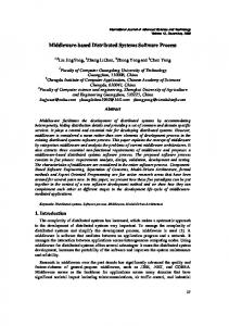
A simple example of sequence diagram of system’s external behavior concerning the use case « buy items » which belongs to the e-commerce web site case study is given in Figure 1. In this sequence diagram, we present the shopper that adds repeatedly several desired items to its cart. Then, the system searches the item information (price, description, quantity in stock…) and it displays the total of the cart for each item added.
: Shopper Loop [More items] Add item to the cart (code item, quantity)
: Web Site E-commerce Shopper choose item present in stock Search Item
Display cart total
Figure 1. Example of Sequence Diagram of System’s External Behavior (buy items) On the other side, The SDSEB meta-model (Figure 2) that we have proposed for our transformation approach as first source model represents a system as set of combined fragments of operands which in turn contains several ordered messages. A message can be internal or external one involved by actors (called also incoming message). A message comes only from one actor and might contain parameters. However, an actor might be principal: the actor responsible for triggering or initiating the use case and
Copyright ⓒ 2013 SERSC
171
International Journal of Software Engineering and Its Applications Vol.7, No.5 (2013)
aspect the observable system result; or secondary actor: the actor solicited for completing the information necessary for the execution of the use case. We can see that the proposal meta-model is slightly different from the standard UML sequence diagram [10, 11, 13] without opposing it or to the MOF [14]. Indeed, the SDSEB is a specific sequence diagram that contains only external system interaction with actors without considering the internal ones. Therefore, its meta-modeling seems to be necessary to automate this model transformation. 3.2. Analysis PIM: Domain Classes Diagram The class diagram is one of the leading diagrams in a UML modeling. It allows dissecting the system by showing its different classes; it provides a static view of the modeled system. The class diagram is also used to represent a domain model by identifying the system’s classes that participate in the execution of any use case. This model explains the structure of the application domain rather than the application structure itself. It focuses on the domain concepts, rather than on the software components. However most of the domain elements will be present in the design model later new ones could even appear. Parameter name : EString
Condition -clause :EString
0..* have 1
guards 0..* 1
InteractionOperand
Message operand
message 0..*
0..1
operands1..*
PrincipalActor
params
Response name : EString
name : EString order : EInt StartTime :EInt
1
E dTi
1
EI
Internal
Loop
Opt
actor
1
SecondaryActor
sent
Incoming
fragmen 0..1 name : EString t CombinedFragment
Alt
receive
Actor name : EString
1..*
Asynchronous
Synchronous
Figure 2. Meta-model of Sequence Diagram of System’s External Behavior A domain model, often referred to an analysis model, belongs to the analysis phase. Therefore, we are just content in this phase of the software process to determine the different classes without bothering to find their operations because we will find them next through the operation contract. So, the domain class diagram (DCD) represents system’s classes, their relationships and only their attributes without representing their operations. The DCD of the proposed example shown in figure 3 presents the system’s classes that participate in the execution of the use case: «buy items». The class Cart contains a set of cart lines. Each cart line concerns an item that can be retrieved from the catalog.
172
Copyright ⓒ 2013 SERSC
International Journal of Software Engineering and Its Applications Vol.7, No.5 (2013)
LineCart
Cart -Idcart : int /total : float
1
0..*
lines
Item
+quantity : int /amount :float
concern
0..*
1..1
-code :int
item +description: String
+Price : float items 0..*
Catalog +idcatalog :int
1
Figure 3. Domain Class Diagram of the Use Case « buy items » In Figure 4, we present a simplified meta-model of DCD [10] that respects the MOF. The DCD’s meta-model shows the classes with their owned attributes and relationships. The operations will not be presented at this level. The class may inherit from other ones and has properties which are typed elements. Each association describes a set of tuples whose values refer to typed instances. An instance of an association is called a link. A link is a tuple with one value for each end of the association, where each value is an instance of the type of the end. Classifier Classifier -name : EString
Association 0..1
-name : EString
classifier
PrimitiveType association 1..1
DataType
2..*
Enumeration 0..1
type
ownedEnds
Propoerty
*
Class -isAbstract : EBoolean -isController :EBoolean
1..1
1..*
-name : EString -isDerived: EBoolean -default: EString
ownedattributes
0..*
superclass
Figure 4. The Simplified Domain Classes Diagram Meta-model [10] 3.3. Sequence Diagram of System’s Internal Behavior 3.3.1. SDSIB Overview: While The SDSEB is a UML sequence diagram that shows only interactions between actors and the whole system as unique entity which is represented by one lifeline without focusing on system objects interactions, the SDSIB shows ordered interactions between objects with their lifeline and the exchange of messages between them. In addition to these elements generally these sequence diagrams represent the object activated by a rectangular lifeline. When an object is not active, just existing, it has a dashed lifeline. Along the time axis, timing notes or marks
Copyright ⓒ 2013 SERSC
173
International Journal of Software Engineering and Its Applications Vol.7, No.5 (2013)
can be added. These timing marks can be used to give constraints, like specifying the maximum time a message exchange may take. This diagram is one of the most relevant interaction diagrams in design phase. Indeed, in the analysis phase we have established the DCD that contains only Classes without methods. To determine these methods we have to study the interaction between the system’s objects while executing each use case, so we can conclude the different methods through the exchanged messages between objects. To obtain software that is easy to change and to maintain it is recommended not to allow the actors to interact directly with the business objects to avoid creating a strong coupling. This can be resolved using the MVC design pattern. In Figure 5 below we present a SDSEB and a SDSIB with the different elements of the MVC design pattern. System
System Actor
: GUI
Actor message
message
: Controller
: Model
Operation1 () Operation2 ()
Operation3 ()
response
Operation4 ()
response Sequence diagram of system’s External behavior
Sequence diagram of system’s internal behavior
Figure 5. Simple SDSEB and SDSIB Sequence Diagram 3.3.2. Meta-model of SDSIB: Figure 6 shows the proposed target meta-model of SDSIB that presents the different messages sent by the actors implied in the uses case. For each incoming message a set of operations that represents the exchanged messages or interactions between objects will result. The operation may have parameters and return a value and it is concerned by two objects: source object that represents the object that will invoke the operation and target object that will contain and release the operation. As it was mentioned above, we specify three types of objects to implement the MVC design pattern: View, controller and model. Each operation belongs to an interaction operand that can be placed in combined fragment (loop, ALT…).
174
Copyright ⓒ 2013 SERSC
International Journal of Software Engineering and Its Applications Vol.7, No.5 (2013)
1..*
InMessage name : EString order : EInt
1..*
sent
PrincipalActor
Actor name : EString
1 actor
SecondaryActor
1..* operations 1
guards 0..*
Operation
1 0..*
0..*
name : EString order :EInt
parameters
Parameter name : EString
1 type
Condition -clause :EString
operations
0..1
InteractionOperand
operand
1
operands 1..*
DataType return name : EString
fragment 0..1
Enumeration
1 target
System 1 name : EString
1..* classes
1
source
CombinedFragment
Class name : EString
TypePrimitive Alt access
Loop
Opt
1 view
View name : EString
Controller name : EString
Model name : EString
Figure 6. Meta-model of The Sequence Diagram of System’s Internal Behavior We can see that the proposed meta-model is slightly different from the standard UML sequence diagram [10, 11, 13] without opposing with it or with the MOF [14]. Indeed, the SDSIB is a particular sequence diagram that contains whole interactions to respond to the message incoming from actors to the system. Therefore, its metamodeling seems to be necessary to automate software development process. On the other side, The SDSIB meta-model present several ordered operations. An operation has parameters and a return value. Each operation has also two extremities: source class and target class which can be any kind of classes (view, controller or model). Each operation concerns an incoming message trigged by an actor which can be principal or secondary. 3.4. Operation Contract Meta-model 3.4.1. Introduction to LARMAN Operations Contracts: A LARMAN Operation Contract identifies system state changes for each incoming message. Indeed, when system receives an incoming message an interaction between the system objects will be initiated in order to respond to this message. Thereby, to better understand how the system will react to response to this incoming message a contract is defined to highlight these interactions and describe consequently the new system state. Generally, uses cases are the primary mechanism in the software development process to describe system behavior, and are usually sufficient. However, sometimes a more detailed description of system behavior has value. Contracts describe detailed system’s behavior in terms of state changes to objects in domain model, after a system operation has been executed [3]. So, a domain model is useful to help generate an operation contract. An operation contract is a textual description that shows the system state changes, by determining the pre-conditions and post-conditions. While the pre-conditions consist in
Copyright ⓒ 2013 SERSC
175
International Journal of Software Engineering and Its Applications Vol.7, No.5 (2013)
determining the initial state of the system or otherwise the objects created underway before executing the operation. The post-conditions describe the system objects state after operation completion. The main elements of an operation contract are: - Name: Name of the operation with its parameters. - Cross Reference: uses cases. - Pre-Conditions: Initial state of the system (Existing objects underway) before operation is done. - Post conditions: State of system objects after completion of operation. The Graig LARMAN predefined post-conditions are: - Objects created or destroyed. - Associations formed or broken. - Attributes modified. Thus, the operation contract of the operation "addItem (code: int, Qt: int)" concerning the incoming message “add item to cart” in the SDSEB is written as follows: Operation contract of Larman for the operation addItem Operation: addItem(code :int, inquantity :int) Cross References: Buy items Pre-conditions: There are objects cart C and Catalog CA underway Post-conditions: - An instance LineCart LC was created (Instance creation) LC.quantity became quantity(Attribute modification) LC was associated with an item IT (Association formed) LC was associated with a Cart C (Association formed)
The main objective of our model-driven approach is to obtain a sequence diagram of system’s internal behavior by presenting the interactions between system’s objects and specifying the objects source and destination for each operation. The contract as it is defined by Graig LARMAN [3] indicates only the post-conditions that will be transformed to operations without determining the responsible objects for these postconditions, i.e.,: source and target objects. Thereby, it will be necessary to determine them for tracing complete interactions. 3.4.2. A Semantic for Operations Contracts: Operation contract proposed by LARMAN describes only the change of system state in terms of creation, destruction, associations of objects, attribute changes and their resulting operations without specifying how they are going to be invoked, in other words what is the object source which requests for the resulting operation and which responsible object will execute the operation? Also these operations contracts do not cover post-conditions regarding display or calculate, print and check messages and their related operations. Therefore, it is not complete to draw full interactions between objects and deduce specific operations issued from some incoming messages in the SDSEB like display, check or print. Generally, after the completion of these contracts, designers apply manually General responsibilities Assignment Software Patterns (GRASP) to assign responsibilities to the object in charge to achieve the post-conditions. To remedy these shortcomings, we
176
Copyright ⓒ 2013 SERSC
International Journal of Software Engineering and Its Applications Vol.7, No.5 (2013)
propose in our MDA approach a new semantic to represent post-conditions with a formal syntax that includes GRASP and that allows generating not only the operations, but also deduces their objects source and responsible with integrating the new postconditions regarding display, print and check messages were added. The pre-conditions presented in the operation contract of LARMAN contain the necessary objects already created for executing the operation. They are also called candidate objects. However, in this paper the proposed semantic for the post-conditions contain the element responsible for operation completion. In this case, we don’t need to indicate the pre-conditions; in other words the candidate objects. Therefore, in this new Semantic for Operation Contract (SOC), we have focused only on the post-conditions without considering the preconditions because they are sufficient to obtain operations. The new SOC’s post-conditions are used to determine automatically in common sense the interactions between objects based on new formal syntaxes. Thus, SOC allows designers to avoid design mistakes, by providing exact source and responsible objects participant in the interaction and thus improves the quality of modeling. Regarding display, print and check messages, new post-conditions are created. Before applying SOC to the running example presented above, we will introduce the various elements of the SOC and the resulting operations of each post-condition written in its new syntax. 3.4.3 The new Semantic for Operation Contract (SOC): With regard to integrate the GRASP operation contract and generate automatically resulting interactions, we have proposed a new semantic SOC that integrates all post-conditions presented by LARMAN and proposes new details and defining new precise and formal syntax for post-condition. For example, the creation post-condition as it is defined by LARMAN: “Subject class was created” does not determine the responsible object which will be charged to send the operation “create” to the subject class in order to instantiate it. However, the alternative syntax in SOC: "Subject class was created by Responsible class" specify the element responsible for the creation and integrate the GRASP known as (Creator) which allow deducing that the operation “create” has the responsible object as source and the subject class as the responsible one. Otherwise, the new syntaxes used in SOC incorporate the GRASP concepts that represent the guidelines for assigning responsibility to classes and objects in object-oriented software system to determine correctly the interactions. Appropriate assignment of responsibilities to classes is the key to successful design and there are fundamental principles in assigning responsibilities that experienced designers apply. These principles are summarized in the GRASP patterns acronym for General Responsibility Assignment Software Patterns. They are nine core principles that object-oriented designers apply when assigning responsibilities to classes and designing message interactions: Creator, Expert, Controller, Low Coupling, High Cohesion, Polymorphism, Pure Fabrication, Indirection and Protected Variations [23]. An overview of the most important GRASP used in SOC was given as following: - Low Coupling: As long as there are many couplings between objects, classes become less progressive. We must therefore minimize the liaisons between the objects and add them only when necessary. - High Cohesion: The methods of a class must be unitary and consistent. A class of low cohesion doesn’t perform operations that are outside its responsibility and doesn’t have several ones in the same method.
Copyright ⓒ 2013 SERSC
177
International Journal of Software Engineering and Its Applications Vol.7, No.5 (2013)
- Expert: A business object has to do what it knows, i.e., the object which knows or owns the information is the one which can do the operation. - Creator: A system object must create what it contains, a class can create an instance of another class if it contains or aggregates their instances or it often saves it. - Controller: Acts as an orchestra, it is responsible for responding to requests issued from the GUI layer by controlling the exchange of operations between different domain objects. - Pure Fabrication: Objects were not found in the domain of the application, but we can introduce them to maintain the high cohesion and low coupling between classes, Data Access Objects that are responsible for Create/Retrieve/Update/Delete (CRUD) operations with the database and printer classes are examples of this grasp. To apply the SOC in our model-driven approach and to determine completely all system interactions, the designer must respect and give the inputs of the post-conditions correctly. Thus, they can generate the operations signatures and the interaction responsible objects. Each post-condition has its own formal syntax and its inputs could be optional or required. The post-condition has as possible inputs: subject class, responsible class, associate class, multiplicity, attribute and parameter. The Tables 1, 2, 3, 4 below represent the formal syntax of the proposed SOC which takes all the post-conditions already defined by LARMAN and proposes a new formal and precise syntax for each one by integrating GRASP and matching them to operations signatures. The SOC propose new extended post-conditions “Display” “Check” and “Print” which are not expressed before by LARMAN as post-conditions. The first Table 1 of the toolset SOC concerns the creation, modification and destruction post-conditions. While the post-condition creation allows creating a subject class instances, the destruction post-condition destruct them. The syntaxes for these post-conditions concerning the subject class LineCart are respectively: “Line_Cart was created by Cart” and “Line_Cart was destructed by Cart”. We can see that the element Cart is added to specify the responsible object for these post-conditions. In other side, the post-condition modification allows modifying the subject class’s attribute value through the post-condition parameter. For example, “Line_Cart quantity was modified to inquantity”, illustrates that the quantity attribute takes the value inquantity, the parameter of the post condition. The second Table 2 concerns the association and disassociation post-conditions necessary to establish or to break the association between the subject class and the associate class. In some cases, the associate object must be found before performing the post-condition. For example in the following post-condition: “Line_Cart was associated with an item retrieved from catalog by code”, code is a parameter to search items present in catalog. The third Table 3 regards Display post-condition that covers both the screen display event and calculating operations. For example, if the Cart total must be calculated, the designer has to formulate the post-condition as following: “Cart total which is derivable from amount was displayed”. Otherwise, if we want to display it on the screen the related post-condition display will be expressed as following: “Cart total was displayed on screen”.
178
Copyright ⓒ 2013 SERSC
International Journal of Software Engineering and Its Applications Vol.7, No.5 (2013)
The other new post-conditions check and print described in Table 4 allow checking and printing system events. The post-condition check is used to verify the attributes of some domain classes with the entered parameters like check the card code before making a bank transaction in ATM, the related check syntax will be “Card Code was checked with incode”, incode is the parameter entered by the cardholder. When, the post-condition print allow identifying print operations concerning subjects classes which are printable like tickets, commercials orders etc. For example if we want to print an ATM ticket, the designer must write “Ticket was printed”. Finally, the whole tables present new syntax and the GRASP applied to generate the interaction for each one. 3.3.4. Applying SOC to the Running Example: Applying the SOC, the new postconditions syntaxes for the running example defines the following post-conditions: Operation contract of the operation addItem Operation: addItem (code: int, inquantity: int) Cross References: Buy items Post-conditions: LineCart was created by Cart LineCart quantity was modified to inquantity LineCart was associated with an item retrieved from Catalog by code LineCart was associated with Cart LineCart amount which is derivable from quantity and price was displayed Cart total which is derivable from amount was displayed - Cart total was displayed on screen
In a second step, based on SOC, we obtain for each post-condition the signatures of operations and their corresponding source and destination objects represented in a partial sequence diagrams. post-condition : LineCart was created by Cart Meta-model inputs :
: View
: Controller
C: Cart
LC: LineCart
: Shopper
Subject class : LineCart Responsible : Cart
Add Item addItem(code:int,inqunatity:int) LC=createLine( )
Copyright ⓒ 2013 SERSC
LC=LineCart()
179
International Journal of Software Engineering and Its Applications Vol.7, No.5 (2013)
Table 1. Concerning the Post-conditions: Creation, Destruction and Modification Name
Formal Post-condition Syntax : Subject class was created by responsible class Creation
Operations signatures & interactions
Description and generating operations
Creation of a subject class instance
1- create[Subject class name]():Subject class : Controller
1- Operation “create” outcomes from controller to responsible class for creation 2- Constructor with same name as subject class is invoked by responsible.
Meta-model Inputs
:Responsible class
Subject, responsible
2- [Subject class Name] () : Responsible class
: Subject class
Applied GRASP: “Creator, Controller”. The responsible class must save, contain or compositely aggregate instances of subject class. In this case the responsible will be charged to create the subject class instances. The controller is the object that receives calls from outside and coordinate between system’s objects. Subject class Attribute was modified to parameter
Modification
Modification of subject class attribute: Modify value of subject class’s attribute with the value of post-condition’s parameter. The type of parameter will be deducted from the corresponding domain attribute. If the post-condition modification is directly preceded by the following post-conditions: creation(C), or destruction (DE), or association (A) or disassociation (DI): an operation “set” is sent from controller class to subject class.
Modification isn’t directly below the following post-conditions in SOC: (C, DE, A, DI) set[Subject class attribute name] (parameter name : attribute type) : void : Controller
: Subject class
Else
Subject, attribute, parameter
set[Subject class attribute name] (parameter name: attribute type) : void
:Subject class
Else : An interoperation “set” of the subject class is generated.
Destruction
Applied GRASP: “Expert and Controller”. The subject class is responsible for attributes modification because it knows them. Subject class was destroyed by responsible class
1- destruct [Subject class name]():void
Destruction of a subject class instance
: Controller
1- Operation destruct sent from controller to responsible class for destruction 2- A Destructor of subject class with same name as its subject class but it is prefixed by “$” to distinguish it from the constructor.
: Responsible class
Subject, responsible
2-$[ Subject class Name] () : Responsible class
:Subject class
Applied GRASP: “Creator”, it’s the same as the post-condition creation. The responsible for the subject class instances creation. It’s also responsible of their destruction.
180
Copyright ⓒ 2013 SERSC
International Journal of Software Engineering and Its Applications Vol.7, No.5 (2013)
Table 2. Concerning the post-conditions: Association and Disassociation
Association Formed with parameter
Name
Description and generating operations Formal Post-condition Syntax : Subject class was associated with an associate class retrieved from responsible class by parameter Association formed between Subject and Associate classes that must be found first by a parameter 1- Operation “find” outcomes from controller to responsible class which retrieves the object associated by the post-condition parameter.
Operations signatures & interactions
Meta-model Inputs
1- find[Associate class name] (parameter name : : Controller
attribute type):associate class : Responsible class
2- set[Associate class name]( x : associate class):void : Subject class : Controller
Subject, responsible, associate, parameter
2- Operation “set” is sent from the controller to the subject class to perform the association Applied GRASP: “Expert and low coupling” before performing association, the associate class was found in the responsible class because it knows it. The controller is the best candidate object to invoke operation “find” to avoid dependency between classes.
Association Formed without parameter
Subject class was associated with an associate class Association formed between the subject and the associate class without an incoming parameter
multiplicity_max =-1 add[Subject class name] (subject :subject class):void : Controller : Associate class
1- if multiplicity_max =-1 in the multiplicity_max !=-1 domain model (otherwise, associate set[ Subject class name](subject: subject class is a set of subject class ) an class):void operation add outcomes from controller : Controller to associate class :Associate class 2- else, the operation set outcomes from
Subject, associate, multiplicity _max
the controller to the associate class
Disassociation with parameter
Applied GRASP: Expert and controller. It’s the same as the modification post-condition with parameters. Subject class was disassociated with associate class identified by parameter Association braked between the subject and the associate class 1- Operation “find” outcomes from controller to responsible class to retrieve the associate object by the post-condition parameter.
1- find[Subject class name] (parameter name: attribute type):subject class : Controller
: Associate class
2- remove[subject class name] (subject: subject class) : void : Associate : Controller class
Subject, associate, parameter
2- An operation “remove” will results from the controller to the associate class to break association
Applied GRASP: “Expert and low coupling”. It’s the same GRASP applied in the post-condition association formed with parameter
Copyright ⓒ 2013 SERSC
181
Disassociation Without parameter
International Journal of Software Engineering and Its Applications Vol.7, No.5 (2013)
Subject class was disassociated with associate class Association braked between the subject and the disassociate class without an incoming post-condition parameter
disassociate[Subject class name](subject: Subject class) :void : Associate class
: Controller
Subject, associate,
- The operation “setNull” outcomes from the controller to the associate class to brake association
Applied GRASP: Expert. It’s the same GRASP applied in the post-condition association formed without parameter
Table 3. Concerning the Post-condition: Display Name
Description and generating operations
Display
Formal Post-condition Syntax : Subject class attribute which is derivable from calculating attributes and parameters was displayed Onscreen=false Display event allows displaying subject class attribute’s values by calculating or simply displaying them on screen. 1- If the post-condition syntax does not contain the expression “on screen” and the displayed attribute is derivable from other calculating attributes. First, If there is no previous creation (C), destruction(DE), association(A), disassociation(DI) postconditions in SOC before display, an operation calculate will result from controller to subject class 2- Else, calculate is an interoperation existing in the subject class Next other operations to retrieve calculating attributes will be necessarily created to calculate or to display the concerned attribute. If the calculating attribute does not belong to the subject class features then 2.1 - “get” out of the calculating attribute resulting from subject class to the class that contains the calculating attribute 2.2- Else, “get” out of the calculating attribute is an interoperation in the subject class calculating attribute 3- Finally, to avoid recalculating the derived attributes to display, another operation “set” will be added to the subject class.
Metamodel Inputs
Operation signature
Onscreen=false
Display isn’t directly below the following postconditions in SOC: (C, DE, A, DI) 1- calculate[subject class attribute name] ( param: param type…): : Controller
:Subject class
Else 1- calculate[subject class attribute name ](…) : attribute type : Subject class 2.1) Calculating attribute isn’t a subject class feature
2.1-get[class calculating attribute name](pram: param type): class calculating attribute type
Subject, displayed attribute, calculating 2.2) calculating attribute is a subject class feature attribute, 2.2-get[class calculating attribute name]() : parameter
: Subject class
: Class calculating attribute
class calculating attribute type
: Class calculating attribute 3) Avoid recalculating attribute to display
3- set[subject class attribute name] (attribute name: attribute type) :void
:Subject class
182
Copyright ⓒ 2013 SERSC
International Journal of Software Engineering and Its Applications Vol.7, No.5 (2013)
Subject class attribute was displayed on screen Onscreen=true If the post-condition syntax contains the expression “on screen”. The only operation display will outcomes from controller to the view.
Onscreen=true
2.1- get[subject class attribute name](): attribute type : Subject class : Controller 2.2-display[subject class attribute name](): void : View
: Controller
Applied GRASP:”Expert and High cohesion”. The class which knows the information is responsible to display it. The subject class is focused to calculate its appropriate information to avoid cohesion with other ones.
Table 4. Concerning Post-conditions: Check, Print
Check
Na me
Operations signatures & interactions
Description and generating operations
Subject class attributes were checked If Display isn’t directly below the following postconditions in SOC: (C, DE, A, DI) with post-condition parameters : Post-condition Check allows checks or verifications between its parameters and check (parameter 1 name: attribute 1 type ,…): attributes of the domain classes boolean If it isn’t directly below the following : Subject class post-conditions in SOC: creation (C), : Controller destruction(DE), association(A), Else disassociation (DI) post-conditions in SOC then an check (parameter1 name:attribute1 type,…) : operation “check” that outcomes from boolean controller to the subject class will be created in SDSIB Else, The Post-condition will be mapped to :Subject an interoperation “check”. Note, The result of the operation is boolean value
Metamodel Inputs
Subject, parameters , attributes
print
Applied GRASP: “Expert and Controller”. The subject class knows its attributes. Therefore it is responsible to check them with parameters. Subject class was printed Post-condition print allows identifying print operations concerning subjects classes which are printable like tickets, commercials orders The operation “print “outcomes from controller class to printer class and probably has parameters
print[Subject class Name] (parameter name : attribute type) : void : Controller
: Printer class
Subject, parameter,
Applied GRASP: “Pure Fabrication and Controller”. Class printer does not belong to the domain classes, but we create it to maintain the high cohesion and low coupling between classes
Copyright ⓒ 2013 SERSC
183
International Journal of Software Engineering and Its Applications Vol.7, No.5 (2013)
The second post-condition concerning modification of quantity property gives the following interactions:
post-condition : LineCart quantity was modified to inquantity Meta-model inputs : Subject : LineCart Modified Attribute : quantity Parameter: inquantity
LC: LineCart
C: Cart
: Controller
LC=createLine() LC=LineCart() LC.setQuantity(inquantity :int)
post-condition : LineCart was associated with an item retrieved from Catalog by code Meta-model inputs : Subject : LineCart : Controller LC: LineCart C: Cart Responsible : Catalog IT=Cat.findItem(code :int):Item Associate : Item Parameter: code
CA: Catalog
LC.setItem(IT:Item):void
post-condition : LineCart was associated with Cart Meta-model inputs : Subject class : LineCart Associate : Cart Multiplicity_max: -1 (many)
: Controller
C: Cart
LC: LineCart
C.addToCart(LC) :void
The Figure 7 shows the métamodèle of the operation contract. In this métamodèle, each incoming message has a contract that contains various post-conditions, which is an abstract class. The designer can only instantiate the classes that are inherited from it, i.e.: creation, destruction, modification, association, disassociation, display, check and print. A creation or destruction post-condition needs a subject object and an object responsible for the creation or the deletion of the subject class instances. Regarding, the post-condition modification, we must indicate the subject class attribute called “modified” attributes in the SOC meta-model and its corresponding post-condition parameter. In this case, the type of the modification parameter is not required because it will be deduced from the domain attribute type. With regard to the Associations and disassociations post-conditions, in addition to responsible and subject objects, we have to indicate the associate object. In some case we have to retrieve the associate object in order to perform association or break it. In this case, we must provide the search key as a parameter of the post-condition as well as the responsible object for retrieving the associate object. Concerning the new post-conditions proposed in SOC, first the post-condition display may simply be an on-screen display or represents a calculation. Furthermore, we must indicate the subject class attribute that will be displayed and the calculating attributes to accomplish the post-condition when it is a calculation post-condition. The
184
Copyright ⓒ 2013 SERSC
International Journal of Software Engineering and Its Applications Vol.7, No.5 (2013)
Boolean property “Onscreen” of the post-condition allows distinguishes between these kinds of messages. Finally, the post-condition check allows verifications of the subject class attributes called “Checked” attributes with the post-condition parameters. The post-condition print allows identifying print operations concerning the printable classes like tickets, commercials orders and it has also parameters like order date, order number etc. post-conditions : LineCart amount which is derivable from quantity and price was displayed Cart total which is derivable from amount was displayed Cart total was displayed on screen Meta-model inputs : Subject : : Shopper LineCart Displayed attribute : total, amount Calculating attributes : quantity, price, amount
: Controller
: View
IT: Item
LC: LineCart
C: Cart
price=IT.getPrice():float qt=LC.cgetQuantity():int
M=LC.calculateAmount():float LC.setAmount(M):void M=LC.getAmount():float T=C.calculateTotal():float
displayTotal():float
T=getTotal():float
C.setTotal(T):void
Display Cart total
Type name : EString
WrapperType
Contract name: EString
InMessage name : EString
applied 1
1
inmessage type 0..1
1..*
PrimitiveType
postconditions 1..*
1..*
Postcondition
Parameter name : EString
0..* parameters
0..1
1..*
Class
associate
order :EInt syntax: EString
0..1 responsible
1
name:EString
1
Disassociation
subject
Association Modification
Display
Check
Onscreen :EBoolean
Creation 0..*
0..*
Destruction
modified
0..*
1
Attribut 1
Print
displayed calculating 0..*
name: EString 0..* visibility :EString checked isDerivable :EBoolean 0..*
attributes
Figure 7. Operation Contract’s (SOC) Meta-model
Copyright ⓒ 2013 SERSC
185
International Journal of Software Engineering and Its Applications Vol.7, No.5 (2013)
4. Model Transformation Models are the core of the software development process. Since each iteration involves the generation of a new model based on previous ones; it becomes clear that software development defines a model-driven development process [12, 15]. Thus, once we have defined the meta-models to be considered, the remaining step to complete automating the software process according to MDE principles is to define the mappings between them in order to specify how each different model considered is going to be generated during the process. We can refer to this mapping as model transformation [16]. Although the main objective of this work is to present an approach to automate the whole software development process by presenting the necessary meta-models and model transformation at the different modeling levels, we will present here only the transformation allowing the generation of the interested target model: the SDSIB. Therefore, our transformation has been defined as a model-to-model (M2M) exogenous transformation that takes principally a specific UML sequence diagram SDSEB as input and produces an extended one with more details called the SDSIB. To perform this M2M transformation, we have proposed the following method: First, the mappings between models are defined using natural language. Then the mapping rules are implemented using ATLAS Transformation Language [17-19]. ATL is a domain-specific language for specifying model-to-model transformations. It is a part of the AMMA (ATLAS Model Management Architecture) platform. ATL is inspired by the OMG QVT requirements [20] and builds upon the OCL formalism [21]. It is also considered as a hybrid language, i.e., it provides a mix of declarative and imperative constructs. The choice of this language is justified by the possibilities that offer in performing transformations. Indeed, in this approach we need to transform an SDSEB to an SDSIB using the DCD and SOC which means that we use a several meta-models as input in this transformation which is not supported by the standard QVT. We have proposed the following method to develop our model transformation: - First, the mappings between models are defined using natural language. - Next, those mappings are structured by collecting them in a set of rules, expressed again with natural language. - Then the mapping rules are implemented using one of the existing model transformation languages. In this case we have chosen the ATL language. - Finally, a validation of the model transformation is given to avoid to make the probably errors input in SDSEB, DCD and SOC before obtaining the expected model SDSIB. For this, a validation report is generated. In the next section we will present at Table 5 the different rules of the transformation in a natural language and their implementation in ATL. The Table 5 presents how the expected SDSIB was obtained by matching its different elements with the corresponding ones in the source models SDSEB, DCD and SOC. Therefore, the rule 1 concerns the creation of the design Pattern MVC particularly the objects View and controller. The controller can be retrieved from domain if there is a domain class specified in DCD as controller of whole system or create a new one otherwise. While, the rule 2 matches the domain classes of the DCD with the model classes of the SDSIB without recovering their attributes, rules 3, 4, 5 allow mapping the combined fragments that contain incoming messages and their triggers actors. Every combined fragment like
186
Copyright ⓒ 2013 SERSC
International Journal of Software Engineering and Its Applications Vol.7, No.5 (2013)
“loop” applied in the running example on the SDSEB message will be applied this time in SDSIB on resulting operations. Finally, the remaining rules 6, 7, 8, 9, 10, 11 describe how the new semantic postconditions used allow generating different operations including their source and responsible objects to represent the entire interaction in SDSIB. In order to perform this transformation other called rules was used to accomplish the mapping like “predecessor()” that allows return the post-condition which immediately precedes the current post-condition passed in parameter to determine later the type of the resulting operations: those which are internal or meanly outcomes from another object. The following called rules “getCheckName()”, “getParameters()” and “toCapitalize()“ were also used to build correctly the signature of the operations. 4.1. The Transformations Rules In this section, we will introduce some transformation rules written in ATL that was already written in a natural language. The goal is to bring our approach closer to readers and make them familiar with the principles on which the transformation is based. Thus, we will just present the transformation rules that allowed us to obtain the MVC design pattern, matched rules concerning the incoming message and the according extended post-conditions. For this, we have chosen to present solely the creation and modification post-conditions to explain the general rules to incorporate the SOC in our model transformation. ATL Rules to implement MVC: In order to implement the MVC design pattern, we have chosen to create two objects: controller and view in the target model SDSIB to treat the use case described in the SDSEB. Regarding the model classes, the whole domain classes which exist in DCD will be mapped to model classes. Sometimes, the designer chooses a domain class as controller (the value of its attribute isController is assigned to true). Therefore, this class will be the controller in the resulting SDSIB. Otherwise, a new object controller will be created whose name is prefixed by Handler. Matched rule 1 : create an GUI and controller for the system.
rule SDSEB2SDSIB{ from s:MMSDSEB!SDSEB to t1:MMSDSIB!SDSIB(name