Automating the Performance and Reliability Analysis of Enterprise Information Systems. Apostolos Zarras INRIA Rocquencourt Domaine de Voluceau 78153 Le Chesnay - France
[email protected]
Abstract Good quality models for the analysis of complex enterprise information systems (EIS) are hard to build and require lots of experience and effort, which are not always available. A possible solution to deal with the previous issue is to build automated procedures for quality model generation. Such procedures shall encapsulate previous existing knowledge on quality modeling and their use shall reduce the cost of developing quality models. In this paper, we concentrate on the performance and reliability of EIS and we investigate the automatic generation of quality models from EIS architectural descriptions comprising additional information related to the aspects that affect the quality of the EIS.
1. Introduction Todays industrial organizations strongly depend on large scale enterprise information systems (EIS) for performing and managing their complex business processes. In consequence, the quality of the EIS is of significant importance and quality analysis is required during its whole life-cycle. The analysis of certain quality attributes (e.g. performance, reliability, availability) is not a new challenge. Pioneer work on modeling and analyzing the quality of software systems at the architectural level includes AttributeBased Architectural Styles (ABAS) proposed in [3]. In general, an architectural style includes the specification of types of basic architectural elements (e.g. pipe and filter) that can be used for specifying a software architecture. Moreover, an architectural style includes the specification of constraints on using those basic architectural elements and patterns describing the data and control interaction among them. An ABAS is an architectural style, which additionally provides modeling support for the analysis of a particular quality at-
Valerie Issarny INRIA Rocquencourt Domaine de Voluceau 78153 Le Chesnay - France
[email protected]
tribute (e.g. performance, reliability, availability). More specifically, an ABAS provides support for specifying: (1) Quality attribute measures characterizing the quality attribute (e.g. the probability that the system correctly provides a service for a given duration, mean response time); (2) Quality attribute stimuli, i.e., events affecting the quality attribute of the system (e.g. failures, service requests); (3) Quality attribute parameters, i.e., architectural properties affecting the quality attribute of the system (e.g. faults, redundancy, thread policy); (4) Quality attribute models, i.e., traditional models (e.g. Markov chains, petri-nets, queuingnets etc.) that formally relate the above elements. In [2] the authors go one step further proposing a method for architecture tradeoff analysis (ATAM) where the use of an ABAS is coupled with the specification of a set of scenarios, which roughly constitutes the specification of a service profile. In all those cases, quality attribute models (e.g. Markov models, queuing networks etc.) are manually built given the specification of a set of scenarios and the ABAS-based architectural description. However, in [2], the authors recognize the complexity of the aforementioned task. ATAM is a promising approach for doing things right. Nowadays, however, there is a constant additional requirement for doing things fast and easy. Asking EIS engineers to build performance and reliability models from scratch is certainly a drawback towards achieving the previous. The objective of the approach presented in this paper is to overcome the aforementioned drawback by automating the generation of quality attribute models from architectural descriptions. The remainder of this paper is structured as follows. Section 2 provides the definition of a base architectural style for specifying EIS architectures. Sections 3 and 4 introduce the automated procedures for the generation of traditional performance and reliability models. Finally, section 5 concludes this paper with a summary of our contribution.
2. A Base EIS Architectural Style
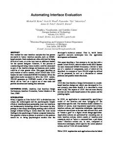
we use here as an example. The case study consists of the quality analysis of an EIS used for managing the Bull SA organization. The basic EIS architecture consists of a variety of autonomous and disparate subsystems. The EIS service profile includes, among others, a workflow which combines services provided by the EIS subsystems into a complex billing service. The workflow consists of: The Bill task, using services of a Log and a Department server to produce per-customer bills; The Payment task, taking as input a bill produced by the Bill task and a reference to the Department server, and checking whether the bill is accepted, or not; The Transfer task, using a Billing server to transfer money from the account of the customer to a bank. The Claim task, using the Billing server to cancel rejected bills. Figure 2, gives a snapshot of the tool we developed showing the specification of the complex billing service workflow.
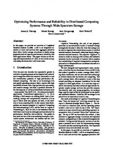
Figure 1 gives the UML definitions of the basic elements for the specification of EIS architectural models.
Figure 1. The structure of an EIS architectural model An EIS is basically the integration of a set of autonomous subsystems, the services of which are combined using workflows. Hence, an EIS software architecture comprises the specification of a non empty set of EIS subsystems providing one, or more EIS services. Every EIS subsystem is deployed on top of an EIS node. Technically, EIS subsystems and services are specified textually using DARWINlike notations. DARWIN is among the first and most popular architecture description languages (ADLs) (for more information see [5]). An EIS architectural description further includes the specification of a service profile. A service profile is defined here as a non-empty set of EIS workflows describing how the EIS is used. An EIS workflow is a model that specifies the coordination dependencies among of a set of EIS tasks. The workflow model we use is inspired by the one proposed in [7], which has recently become an OMG standard [6]. Tasks use basic EIS services provided by subsystems. Hence, a task requires a set of alternative inputs which may be either references to EIS subsystems, or notifications from other tasks. During the execution of a task the first available input set is used to produce a set of outputs (references to subsystems, or notifications to other tasks). By definition, a set of alternative sets of outputs may be produced by a task. Technically, tasks and dependencies among them can be specified textually using the language detailed in [7]. Moreover, textual descriptions of tasks specify the way different alternative input sets are used to produce the corresponding alternative output sets. To facilitate the specification and quality analysis of EIS architectures, we developed a prototype tool. The use of the tool for the specification and quality analysis of EIS has been tested with a real world case study, part of which
Figure 2. The billing service workflow specification.
3. Automated Performance Analysis The basic performance measures used to characterize the execution of EIS workflows and tasks are the mean-servicetime, mean-waiting-time, mean-execution-time, and meansystem-throughput. Moreover, the basic stimuli that cause changes on the values of those measures is the initiation of workflows. Hence, EIS workflows are associated with an attribute whose values give the statistical pattern by which workflows are initiated. Finally, EIS subsystems are characterized by their thread and scheduling policies, their capacity and the work demands needed for providing the associated EIS services. For EIS performance analysis, we use a tool-set, called 2
QNAP2 1 , providing a variety of both analytic and simulation techniques. QNAP2 accepts as input a queuing network model of the system that is to be analyzed. A queuing network model consists of a set of stations providing services requested by customers. A service is associated with a set of transition rules describing what happens to a customer after the customer is served. A station is further associated with queues that store requesting customers. In a queuing network, we may have special stations, called source stations, whose purpose is to create new customers. Those stations are characterized by a statistical pattern according to which they generate customers. Given an EIS architectural description the steps for mapping it to the corresponding queuing network are the following. First, a set of stations is generated, corresponding to EIS nodes on top of which EIS subsystems and workflows are deployed. Moreover, for every workflow specified in the EIS service profile, a source station, characterized by the corresponding statistical pattern, is generated. Then, for every EIS subsystem, a queue is generated and associated with the appropriate station. Performance parameters related to the capacity and scheduling policy of the subsystem are used to define the corresponding properties that characterize the queue. In addition, a service is generated for every EIS service provided by the subsystem. The generated service is characterized by the work-demands required for the corresponding EIS service. In the next step, for every workflow in the service profile and for every task t into this workflow, a queue, tQueue, is generated and associated with the corresponding station. The generated queue is used to synchronize the execution of tasks that depend on t. The queue stores customers sent by tasks that depend on t, requesting its activation. Moreover, the service tService provided to customers queued in tQueue is generated and associated with the corresponding station. The code of tService follows the pattern described below: (1) The initiation of the workflow causes the creation of customers initc sent to the queue of each task t. (2) Serving initc causes the generation of new sets of customers, one per alternative input set required by task t. Each new set of customers is sent to the stations that host queues of the tasks providing the corresponding outputs. (3) initc waits until one of the new customer sets is served. Then, another set of customers is created and sent to the queues that correspond to the EIS subsystems used by t. The exact code generated here depends on the way tasks use EIS services provided by EIS subsystems. (4) initc remains blocked until all of the created customers are served by the EIS subsystems. Then, an output set is produced and customers waiting on stations for this particular output set are unblocked. Finally, customer initc is unblocked and destroyed. Technically, the Darwin and the
workflow parsers are used to parse the EIS architectural descriptions and to generate the above information. Getting back to our example, the three application servers used by the tasks of the BillingServiceWorkflow are multi-threaded and are modeled to have an unlimited capacity. The policy according to which they serve requests is FIFO. Finally, the work demands for providing the EIS services associated with them are constant (we do not provide further details here due to the lack of space). A queuing network for QNAP2 is then generated simply, using the tool functionality, and according to the mapping defined above. In particular, the following elements are generated: 3 stations and the corresponding queues representing the application servers; 4 stations hosting queues used for the synchronization of tasks; a source station whose statistical pattern equals to the one of the BillingServiceWorkflow. To give an idea of the complexity of the resulting model, its total size is 490 lines. More details in [8].
4. Automated Reliability Analysis The basic reliability measure for EIS is the probability that a workflow successfully completes during the lifetime of the EIS. Getting to the reliability parameters, EIS subsystems, tasks and nodes may fail because of faults causing errors in their state. The manifestations of errors are failures [4]. Hence, faults are the basic parameters that affect the reliability of an EIS, while failures are the stimuli causing changes in the value of the reliability quality. Faults and failures are further characterized by properties proposed in [8]. Reliability analysis techniques are typically based on state space models. The specification of large state-space models is often too complex and error-prone. The approach proposed in [1] alleviates this problem. In particular, instead of specifying all possible state transitions, the authors propose to specify the state range of the system, a death state constraint, and transition rules between sets of states of the system. In a transition rule, the source and the target set of states are identified by constraints on the state range (e.g. if the system is in a state where more than 2 subsystems are operational, then the system may get into a state where the number of subsystems is reduced by one). Given the previous information, a complete state space model can be generated using the algorithm described in [1]. Briefly, the algorithm takes as input an initial state and recursively applies the set of the transition rules. During a recursive step, the algorithm produces a transition to a state derived from the initial one. If the death state constraint holds for the resulting state, the recursion stops. Based on the above, in the remainder we detail how to exploit the EIS architectural description to generate the
1 www.simulog.com
3
information needed for the generation of a corresponding complete state space model. The first step towards that goal is to generate a state range definition for each workflow belonging to a given service profile. The state of a workflow is composed of the states of the tasks making up the workflow and the states of the nodes on top of which tasks and subsystems used by tasks execute. The state of a task consists of a state representing the situation of the task itself and states representing the situations of the task’s alternative input and output sets. The situation of a task depends on the kinds of faults that characterize it. For instance, if the task may fail due to permanent faults, its state may be Waiting, Busy, Complete, or Failed. The state of an input (resp. output) set, ioset, is composed of the states of the individual inputs io (resp. outputs) included in the set. After generating the state range definition for a workflow wf, the step that follows comprises the generation of transition rules for every task t of wf and for the EIS nodes. Those rules depend on the kind of faults that may occur. For permanent faults, the rules for task t follow the pattern below: If wf is in a state where t is Waiting then: (1) If an alternative input set ioset is available then wf may get into a state where t is Busy; (2) If none of the alternative input sets ioset may eventually become available then wf may get into a state where all tasks depending on t are aware about the fact that its output sets will never be available. The previous are, typically, fast transitions, i.e. the probability that they take place is close to 1. If wf is in a state where t is Busy due to the availability of ioset then wf may get into a state where: (1) t is Complete; (2) t is Failed and all tasks depending on t are aware about the fact that its output sets will never be available; (the rate of getting into this state equals to the arrival rate of the fault that caused the failure of t); (3) t is Waiting, io belonging to ioset is Failed and all EIS references io’ used by other tasks of wf, for which io’.eisSubsystem = io.eisSubsystem holds, get into a Failed state (the rate of this transition equals to the arrival rate of the fault that caused the failure of io). The rules for a node n are more obvious, and are not given here due to the lack of space. Finally, a death state constraint must be generated. In general, wf is in a death state if none of its output sets may eventually become available due to the unsuccessful termination of the tasks providing the corresponding outputs. Technically, the generation of the information discussed in this section requires using both the parser of the workflow specification language and the parser of Darwin specifications. Getting back to our example, from the workflow specification given in Figure 2 we can generate the necessary information that serves as input to the algorithm presented in [1]. The state of the workflow
is composed of the states of the Bill, Payment, Transfer, and Claim tasks, and the states of the nodes used for the execution of the tasks and subsystems. The overall size of the model used as input for the algorithm [1], is 325 lines of code. The generated complete Markov model contains 616 states. 282 out the 616 are death states. Finally, the model contains 2092 transitions. More details in [8].
5. Conclusion In this paper, we presented an approach for automating the performance and reliability analysis of EIS. The benefits of the proposed approach are both qualitative and quantitative. In particular, the quality of traditional performance and reliability models is assured since the required experience for building them is encapsulated in automated model generation procedures. Moreover, the cost of performing performance and reliability analysis is reduced since the development of the corresponding models is achieved automatically. Finally, the proposed approach renders the use of formal methods for quality assessment more tractable to industrial people. Acknowledgments. This work is partially funded by the IST C3DS and DSoS projects.
References [1] S. C. Johnson. Reliability Analysis of Large Complex Systems Using ASSIST. In Proceedings of the 8th Digital Avionics Systems Conference, pages 227–234. AIAA/IEEE, 1988. [2] R. Kazman, S. J. Carriere, and S. G. Woods. Toward a discipline of scenario-based architectural engineering. Annals of Software Engineering, 9:5–33, 2000. [3] M. Klein, R. Kazman, L. Bass, S. J. C. M. Barbacci, and H. Lipson. Attribute-Based Architectural Styles. In Proceedings of the First Working Conference on Software Architecture (WICSA1), pages 225–243. IFIP, Feb 1999. [4] J.-C. Laprie. Dependable Computing and Fault Tolerance : Concepts and Terminology. In Proceedings of the 15th International Symposium on Fault-Tolerant Computing (FTCS15), pages 2–11, 1985. [5] J. Magee, N. Dulay, S. Eisenbach, and J. Kramer. Specifying Distributed Software Architectures. In Proceedings of the 5th European Software Engineering Conference (ESEC’95), number 989 in LNCS, pages 137–153. Springer Verag, 1995. [6] OMG. UML Profile for Enterprise Distributed Object Computing. Technical report, OMG, 2000. [7] S. Wheater, S. Shrivastava, and F. Ranno. A CORBA Compliant Transactional Workflow System for Internet Applications. In Proceedings of MIDDLEWARE’98, pages 3–18. IFIP, September 1998. [8] A. Zarras and V. Issarny. Quality Assessment of Complex Services. Technical Report C3DS/WPB/T1.5, C3DS Esprit 24962, 2000.
4