University of Calgary. 2500 University Drive, N.W., Calgary, Alberta, Canada, T2N 1N4 ... played an important part in software development since the 1980's.
AUTOMATING THE TRANSITION FROM STAKEHOLDERS’ REQUESTS TO USE CASES IN OOAD Kalaivani Subramaniam, Behrouz Homayoun Far, Armin Eberlein Department of Electrical and Computer Engineering University of Calgary 2500 University Drive, N.W., Calgary, Alberta, Canada, T2N 1N4 {subrama, far, eberlein}@enel.ucalgary.ca Abstract The Object Model Creation Process (OMCP) is considered a major task in Object-Oriented Analysis and Design (OOAD). In the Rational Unified Process (RUP), objects and classes are identified from the use case model, which is a combination of the Use Case diagram and the Use Case Specification (UCS) document. The automation of the generation of the class model assumes that the UCS is complete, accurate and unambiguous. However, in reality, the UCS is written in free form natural language and is therefore likely ambiguous and complex. To avoid this problem, use case templates and guidelines are proposed for writing UCS. This paper presents a methodology to automate the transition from stakeholders’ requests to the use case model. The methodology uses a natural language parser to parse stakeholders’ requests according to various guidelines. The automation process is discussed with an example. Keywords: Use Case diagram; Use Case Specification; Natural language parser; Object Model Creation Process
1. INTRODUCTION Object-Oriented Analysis and Design (OOAD) has played an important part in software development since the 1980’s. Software is becoming increasingly complex; to manage the complexity, OOAD offers various models such as physical model, logical model, static model and dynamic model [1]. The basic building blocks of these models are classes and objects. The identification of classes and objects is considered as a challenging task for software professionals, as there are no well-defined guidelines to manage these tasks. Traditionally, objects
are identified using Data Flow Diagrams (DFD) and Class-Responsibility-Collaboration (CRC) cards [2]. After the introduction of Rational Unified Process (RUP) and Unified Modeling Language (UML), the techniques to identify objects or classes have changed dramatically. The RUP approach focuses on identifying objects and classes from the use case model. Use case analysis is a requirements elicitation technique that is applied in the early stage of the software design process. It is proved to be an effective technique for acquiring functional requirements [12]. The use case model represents the functional requirements in terms of actors and use cases. This model is accompanied by the use case specification document. Considerable research has already been done on how to automate the transition from the use case specification document to the class model [3]. This paper focuses on automating the transition from stakeholders’ requests to the use case model. The structure of this paper is as follows. Section 2 focuses on the methodology behind use case model development. Section 3 focuses on natural language parsing. Section 4 provides the guidelines that are used to identify actors and use cases. Section 5 deals with writing the use case specification document. Section 6 presents the conclusion.
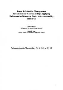
2. METHODOLOGY The methodology is based on natural language processing of stakeholders’ requests and developing the use case model based on predefined rules. The use case diagram and the use case specification are part of the use case model. Fig. 1 shows the architecture of our Use Case Model Generator tool (UCMG). The input of the UCMG is stakeholders’ requests. The output is a use case model consisting of a use case diagram and a use case
CCECE 2004- CCGEI 2004, Niagara Falls, May/mai 2004 0-7803-8253-6/04/$17.00 ©2004 IEEE
- 0515 -
specification. The input requests are analyzed and processed using a natural language parser. A dictionary stores the English words along with their parts-of-speech. A glossary contains any domain specific words. Business rules specify the guidelines to identify actors and use cases. For each identified use case, a stakeholder provides an additional textual description. These descriptions are syntactically verified, formatted according to the use case template and compiled into the use case specification document.
N P
au xV
V
d ro p
VP N P
N
C o u rs e s
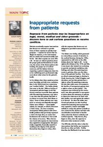
Fig. 2. Parsed Sentence
4. GUIDELINES FOR ACTOR AND USE CASE IDENTIFICATION
Requests Analysis & Processing Stakeholder
Use case Diagrams
Syntactic checking & Formatting
can
VP
Use Case Model
Natural language parser
S tu d e n t
S
Business rules
Glossary
N
Dictionary
Usecase Specification
Stakeholder
Syntactic Rules
Fig. 1. Architecture of Use Case Model Generator
3. NATURAL LANGUAGE PARSING We use the Natural Language Toolkit (NLTK) developed at the University of Pennsylvania [4]. NLTK provides various modules and interfaces to perform parsing. It is simple and can easily be extended. The parser is responsible for splitting text into tokens. Each token is tagged with its part-of-speech. With the help of a dictionary and a set of grammar rules, the parser processes the tagged tokens and produces the parser output. The following example illustrates the parsing operation. Consider the sentence “Students can drop courses”. It is split into a set of tokens and tagged with its part-ofspeech. The tagged text is [‘students’/’N’; ‘can’/’auxV’; ‘drop’/’V’; ‘courses’/’N’]. With the help of grammar rules, the tagged text is parsed into the structure shown in Fig. 2. S: Sentence; NP: Noun Phrase; VP: Verb Phrase; N: Noun; V:Verb; auxV: auxiliary Verb.
Quatrani [5] provides a useful questionnaire to identify actors and use cases. Apart from this, there are several books that focus on the guidelines to identify actors and use cases [6] [7]. These guidelines are very helpful for a manual identification process. However, the structure of the sentence plays a key role in automating actor or use case identification. After reviewing several problem statements and use case diagrams, the following describes some of the rules we adopted in our work for finding actors and use cases. These rules are included in the automation process. Every sentence in the problem statement is compared with the following sentence structure and the respective rules are applied to identify actors and use cases. The given sentence is split into subject and predicate. (a) If Subject only consists of nouns then nouns become the actor and nouns can range from one to many. (b) If Subject is a noun phrase consisting of a sequence of a determiner or article and nouns then the determiner or article is omitted and nouns become the actor. (c) If Subject is a noun phrase consisting of a sequence of a determiner or article, adjectives and nouns then the determiner or article and the adjectives are omitted and nouns become the actor. (d) If Subject is a noun phrase consisting of a sequence of a determiner or article, ing forms of verb and nouns then the determiner or article and ing forms of verb are omitted and nouns become the actor. (e) If Predicate only consists of a main verb then the main verb is the use case. (f) If Predicate is a combination of an auxiliary verb and a main verb then the auxiliary verb is omitted and the main verb is the use case. (g) If Predicate is a combination of a verb and noun phrase then the verb and noun phrase becomes the use case.
- 0516 -
(h)
If Predicate is a sequence of a verb phrase, noun phrase and prepositional phrase where preposition is “to” then the sequence of verb and noun phrase becomes the use case and the noun phrase following the keyword “to” become the actor. The association relationship exists from the use case to the actor. (i) If Predicate is a sequence of a verb phrase, noun phrase and prepositional phrase where preposition is “from” then the sequence of verb and noun phrase becomes the use case and the noun phrase following the keyword “from” becomes the actor. The association relationship exists from the actor to the use case. (j) If the preposition is not either “to” or “from” then the sequence of verb and prepositional phrase is the use case. A sample use case diagram generated automatically by the UCMG tool is shown in Fig. 3.
drawbacks can be overcome by following writing guidelines when developing the use case specification.
Fig. 4. UCS User Interface Table 1. Use Case Specification template [3] 1. 2. 3. 4. 5. 6.
Fig. 3. Use Case diagram
5. WRITING THE USE CASE SPECIFICATION Fig. 4 presents the user interface for writing the use case specification document. The interface lists the actors and use cases for the specific project. The tree view on the left side lists the different sections of the document based on the use case specification template in Table 1. The area below the tree view provides a brief explanation of each section. The user can enter details into the dialog box, and then the tool will validate the text according to the specified pattern [8]. Traditionally, use case specifications are written in one or two paragraphs using free form natural language. Though this is convenient for writing, it had some drawbacks while interpreting the document. These
Use Case Name 1.1 Brief description Flow of Events 2.1 Basic Flow 2.2 Alternative Flow Special Requirements Preconditions Post conditions Extension Points
The UML provides very little guidance on how to write a use case specification. Cockburn presents a lot of information regarding writing use cases [6]. The CREWS (Co-operative Requirements Engineering With Scenarios) research project has proposed several guidelines in writing use case specifications [9]. One of the main concerns when writing a use case specification document is its completeness. It has been shown that CREWS guidelines help to achieve completeness [13]. Canadian Press (CP) Use Case writing rules are considered a subset of CREWS guidelines and they are very simple. Basically CP writing rules are of two types. CP style rules and CP structure rules [10]. Some of the CP style rules that are implemented in our tool are: Each statement should be on a new, numbered line. Alternatives should be in different sections. Avoid pronouns Avoid negatives Avoid adverbs or adjectives Apply present tense for verbs Some of the structure rules that are implemented in our tool are based on the case study. A small case study has been conducted to verify the CP structure rules. We studied about 25 use case specification documents and
- 0517 -
observed the syntactic structures of sentences. The total number of sentences analyzed so far is 314. The most common sentence structures are given in Table 2. Table 2. Sentence Structures A B C D E F G
6. CONCLUSION
Subject // Verb Subject // Verb // Object Subject // Verb //Preposition // Object Subject // Verb // Object // Preposition // Object Subject // Verb // Preposition // Object // Preposition // Object Conditional statements Iterative statements
Fig. 5. shows the percentage of sentence structures used in the use case specification documents analyzed. It shows that the structure B in Table 2 is the most widely used sentence structure. It covers 51% of the total number of sentences that we analyzed. The next widely used structures are D and F. The rest of the structures are less frequently used. The tool also supports the use of concurrent statements. 60 51.2
Percentage
50 40 30
24.2
20 10
11.8 2.9
2.2
2.9
0.9
0 A
B
C
D
E
Statement Structures
F
We also compared the performance of the tool with that of graduate students in a case study. It was found that the tool was beneficial in terms of the time taken to complete the task; and use cases generated by the tool are nearly comparable to that of the manual tasks.
G
Statements
Fig. 5. Statement patterns used in documents Four criteria are used to evaluate the use case specification document. These include completeness, complexity, structure and lack of ambiguity [11]. Completeness is partially achieved by applying structure and style rules. It can also be checked by counting the number of statements in basic flows and alternative flows. On average, alternative flow steps should be approximately 1/4th of the basic flow steps. Basic flow steps should be greater than two. The UCMG tool can also check for certain unambiguous terms. Complexity of the document is directly proportional to the number of alternative flows and conditional statements. So the number of alternative flows and conditional statements in a document are kept less than 4. The UCMG tool generates a report based on these four criteria.
This paper has focused on the automatic generation of a use case model from stakeholders’ requests. These tasks are achieved by using a natural language parser, guidelines and syntactic statement patterns. The guidelines and statement patterns helps to reduce the vagueness of natural language. We believe this tool is helpful to novice software designers for more efficient software design and thereby increasing software design productivity. Thus the reduced time and effort will help to reduce the software development costs and time-tomarket.
References [1] Grady Booch: Object-Oriented Analysis and Design with Applications, Addison-Wesley, 1994. [2] Finding the Objects in an OOP system, http://www.math.grin.edu/~bishopd/csc223/FindingObjects.pdf [3] Dong Liu, Behrouz H. Far, and Armin Eberlein: Automating Transition from Use Cases to Class model, IEEE Canadian Conference on Electrical and Computer Engineering (CCECE 2003), May, 2003. [4] Edward Loper, Steven Bird: NLTK: The Natural Language Toolkit, Proceedings of the Workshop on Effective Tools and Methodologies for Teaching Natural Language Processing and Computational Linguistics, July, 2002. [5] Terry Quatrani: Visual Modeling with Rational Rose 2000 and UML, Addison-Wesley, 1999. [6] Alistair Cockburn: Writing Effective Use Cases, AddisonWesley, 2000. [7] Kurt Bittner, Ian Spence: Use Case Modeling, AddisonWesley, 2002. [8] Dong Liu: Automating Transition from Use Cases to Class Model, Master Thesis, University of Calgary, July, 2003. [9] Colette Rolland, Camille Ben Achour: Guiding the Construction of Textual Use Case Specifications, Data & Knowledge Engineering Journal, March, 1998. [10] Karl Cox, Keith Phalp, Martin Shepperd: Comparing Use Case Writing Guidelines, 7th Int. Workshop on Requirements Engineering: Foundation for Software Quality, June, 2001. [11] Amador Durán, Antonio Ruiz-Cortés, Rafael Corchuelo, Miguel Toro: Supporting Requirements Verification Using XSLT, Proceedings of the IEEE Joint International Conference on Requirements Engineering, September, 2002. [12] Daniel R. Windle, L. Rene Abreo: Software Requirements Using the Unified Process: A Practical Approach. PrenticeHall, 2002. [13] Karl Cox, Keith Phalp: Use Case Authoring: Replicating the CREWS Guidelines Experiment, Int. Journal of Empirical Software Engineering, Issue 5, 245-267, 2000.
- 0518 -