2011 Asian Test Symposium
Automation of 3D-DfT Insertion Sergej Deutsch1,5,7
Vivek Chickermane2
[email protected]
[email protected]
Subhasish Mukherjee3
[email protected]
[email protected]
Mario Konijnenburg4
Erik Jan Marinissen5∗
Sandeep K. Goel6
[email protected]
[email protected]
[email protected]
Cadence Design Systems 1
Brion Keller2
Feldkirchen, Germany Endicott, NY, USA 3 Noida, India
2
IMEC 4
TSMC 6
Eindhoven, The Netherlands 5 Leuven, Belgium
San Jose, CA, USA
TU Braunschweig 7
Braunschweig, Germany
Abstract Using Through-Silicon Vias (TSVs) in three-dimensional stacked ICs (3D-SICs) has benefits in terms of interconnect density, performance, and power dissipation. For 3D-SICs, an extension of the Design-for-Test architecture based on die-level wrappers is required to enable pre-bond die testing as well as modular post-bond die and interconnect testing. This paper presents an approach that automates the insertion of die wrappers. Experimental results show that the user can perform automated 3D-DfT insertion through existing EDA tools with negligible area costs, and verify the proposed DfT by test pattern generation and simulation.
1
Introduction
vides a short overview of the 3D-DfT architecture that has been proposed by Marinissen et al. [5], the automation of which is described in this paper. In Section 3 our 3D wrapper generation flow is introduced. Experimental results are presented in Section 4. Section 5 concludes this paper.
Three-dimensional IC stacking by means of Through-Silicon Vias (TSVs) is a relatively new technology which has a number of advantages over conventional stacking methodologies [1]. TSVs are vertical copper or tungsten conducting nails passing through a thinned die. Typical TSV dimensions are 5μm diameter and 50μm height. The actual connection to the next die can be a direct copper-to-copper bond of the TSV onto a small landing pad, but today is often implemented by means of a CuSn micro-bump, of which typical dimensions are 25μm diameter at 40μm pitch. As they form direct vertical interconnects between stacked dies, TSVs allow a much larger number and higher density of interconnects than conventional wire-bonds. Due to their geometry TSVs have relatively low capacitance and inductance, and thus provide high bandwidth operations and low power consumption [2].
2 2.1
Requirements
A 3D test flow may include pre-bond, mid-bond, and post-bond tests in addition to the final test [6]. A pre-bond test focuses on testing internal die logic; mid-bond and post-bond tests should additionally enable testing TSV-based interconnects. A final test ensures the quality of the outgoing product. All these tests should be supported by a 3D-DfT architecture and optimized for short test time to reduce the overall test costs.
As with all micro-electronics, the manufacturing process of 3D stacked ICs (3D-SICs) is defect-prone. Even if a die is considered to be a Known Good Die (KGD) before stacking, it might need to be tested in the stack to verify that no damage has occurred to the die during the stacking process. To enable modular testing of the die’s internal logic and TSV-based interconnects we need a 3DDfT architecture with die-level wrappers that isolate the dies from the rest of the stack and allow transferring test data up and down through the stack.
A 3D-DfT architecture should be generic in the way that it is not dependent on the number of tiers in the stack and the position of a particular die in the stack. This ensures that a 3D-DfT-inserted die can be used in stacks of different size and on different tiers. An important requirement is modular testing of the stack. A stack can constist of heterogenous modules, e.g. digital logic or DRAMs, which require different test approaches, and thus must be isolated from the rest of the system for testing. Modular testing also enables test access for black-boxed IP cores, for which the integrator has to use pre-generated test patterns. The continuously increasing complexity of systems complicates test generation for an entire system. Modular testing approach reduces the complexity of test generation by allowing only one portion of the system,
This paper focuses on a tool flow for automated insertion of a 3D wrapper based on IEEE Std 1500 [3, 4]. The flow is implemented with the synthesis tool Encounter RTL Compiler (RC) and verified with the ATPG tool Encounter Test (ET) by using a two-die design developed by TSMC for their 3D Reference Flow. The remainder of this paper is organized as follows. Section 2 pro∗
3D-DfT Architecture
Part of the work of Erik Jan Marinissen has been performed in the project ESiP, which is co-funded by the ENIAC Joint Undertaking (http://www.eniac.eu/).
1081-7735/11 $26.00 © 2011 IEEE DOI 10.1109/ATS.2011.58
395
in this case - a die, to be tested at a time. Another benefits are reusing of test patterns for the same die in different stacks, flexible scheduling, and first-order diagnosis.
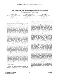
allel TAM for test data (WPI-WPO) to reduce the test length. The wrapper is set in different test modes by loading user instructions into the wrapper instruction register (WIR), which allow to reconfigure the scan chains. Figure 2 shows which combinations of wrapper settings can be made by traversing this so-called “railroad diagram” from left to right [5].
For economic reasons a 3D-DfT architecture should be optimized in terms of low area costs, low number of additional TSVs, and minimum number of extra pins. Since IEEE Std 1149.1 [7] is widely used for board-level testing and debugging, IEEE 1149.1 compliance at board-level is an additional requirement. Dies in a 3D stack may contain IEEE 1500-wrapped IP cores, test data compression circuitry, MBIST, etc.; therefore a 3D-DfT architecture should also be able to work with these DfT structures.
Figure 2: “Railroad diagram” for operating mode set-up.
2.2 Specification
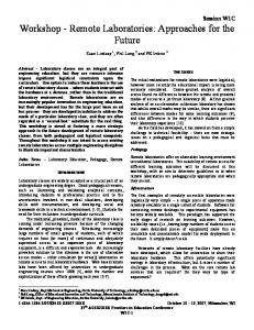
An example of the use of different test mode set-ups is depicted in Figure 3 [5]. In this case the internal logic of Die 2 (Intest) is being tested in a Parallel mode. Die 1 is being bypassed and is transferring the test data up and down (Elevator). Die 3 is not included in the scan path because the die below it is set in a Turn mode. The instruction registers (WIR) of the dies are daisy-chained and loaded through IEEE 1149.1 interface at the bottom die.
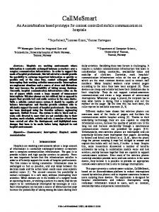
The 3D architecture proposed by Marinissen et al. [5] is based on die-level wrappers. A conceptual overview of the architecture is depicted in Figure 1, which shows an example of a three-die stack. This is a daisy-chain architecture: all dies in the stack are concatenated together so that each die gets the full width of the test access mechanism (TAM). Since only the bottom die in a 3D-SIC holds all external connections, the overall scan chains resulting from the concatenation need to begin and end at the bottom die. To enable test data propagation up and down through the stack, the wrapper has Elevator and Turn modes. The functional I/Os for all dies of the stack, apart from the bottom die, are implemented as TSVs with micro-bumps on top of them [8]. Probing these is challenging, as it involves large numbers of small probe areas at fine pitches and with strict probe damage requirements in order not to inhibit bonding after probing [9]. The probe industry is trying to meet these requirements [10], but as long as that is not the case, additional dedicated probe pads (just for pre-bond testing) seem to be the only solution. The 3D-DfT architecture provides the option of adding a scalable number of dedicated probe pads to a 3D wrapper for pre-bond testing. This feature is optional and not required in case micro-bumps can be probed on without damage [10].
Figure 3: Test mode set-up example for a 3D stack.
2.3
For board-level interconnect testing the bottom die has IEEE 1149.1 boundary scan; the IEEE 1149.1 interface is used to control die-level wrappers.
Implementation
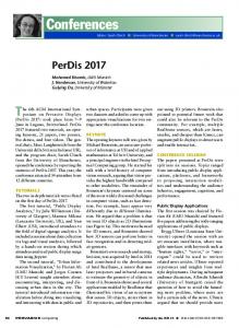
The 3D-DfT architecture can be implemented by enhancing existing standards for testing with features required for 3D. In this paper we focus on an IEEE 1500-based wrapper, but our proposed automation approach can also be applied with an IEEE 1149.1-based implementation. Figure 4 shows a conceptual overview of an IEEE-1500 based wrapper implementation. The wrapper contains the following elements which can also be a part of a conventional (2D) IEEE 1500 wrapper: • • • • • •
Figure 1: 3D-SIC DfT architecture. Apart from a serial TAM for test data and instructions (WSIWSO), the wrapper architecture provides an optional, scalable par-
396
Wrapper Boundary Register (WBR) Serial bypass register (WBY) Wrapper Instruction Register (WIR) Wrapper Serial Control (WSC) Serial and parallel TAM (WSI-WSO,WPI-WPO) Reconfigurable scan chains.
In addition, the 3D wrapper needs to be extended with the following elements to meet the requirements of the architecture: • • • •
The proposed automated generation flow for an IEEE 1500-based die wrapper is similar to IEEE 1500 wrapper automation [11] and differs from it mainly in the set of operating modes. The flow is shown in Figure 5. As input the user needs to provide a structural netlist of the design and the technology library to which the design is mapped. In addition, several parameters need to be defined by the user before running the wrapper generator. In the following sections we focus on different aspects of the wrapper generation flow.
Parallel Bypass Registers Probe pads on the interface (ports with the suffix pad) TestTurns: Turn Registers for a clean timing interface TestElevators: I/Os toward higher-up dies (ports with the suffix s).
3.1
User-Defined Parameters
Before running the wrapper generator several parameters need to be defined. An example of parameter definitions is shown in Figure 6. set WPI WIDTH set WPI PAD WIDTH
3 2
set Bottom PI(0) set Bottom PI(1) set Top PI(0)
data in[0] data in[1] data in[2]
set Bottom PO(0) set Top PO(0) set Top PO(1)
data out[0] data out[1] data out[2]
set TEST MODES
”SerialPrebondIntestTurn \ SerialPrebondBypassTurn \ SerialPostbondBypassTurn \ SerialPostbondBypassElevator \ ParallelPrebondIntestTurn \ ParallelPrebondBypassTurn \ ParallelPostbondBypassTurn \ ParallelPostbondBypassElevator”
set WIR LENGTH
5
set SerialPrebondIntestTurn op set SerialPrebondBypassTurn op set SerialPostbondBypassTurn op set SerialPostbondBypassElevator op set ParallelPrebondIntestTurn op set ParallelPrebondBypassTurn op set ParallelPostbondBypassTurn op set ParallelPostbondBypassElevator op
00010 00100 01100 01101 10010 10100 11100 11101
Figure 4: Implementation of a 3D wrapper.
3
Automated 3D-DfT Insertion
Manually adding a 3D wrapper with several test modes for a realistic design would require a large effort. One reason for it is the large number of operating modes; therefore, automation of this process is essential. In this section we introduce a basic design flow for automated 3D DfT insertion for a flat die on the gate-level for which we use the synthesis tool RC. For the verification of test structures Encounter Test (ET) is used.
Figure 6: User-Defined Parameters. The parameter WPI WIDTH is the width of the parallel TestElevator port. The width of the parallel probe pad port, which is stored in WPI PAD WIDTH, may differ from it. Existing netlist formats do not distinguish between I/Os that are connected to the die below and I/Os that are connected to the die above. As long as this is the case, the user has to define bottom and top I/Os explicitly. In this example we define two bottom and one top inputs, and one bottom and two top outputs. The 3D-DfT architecture as described in Section 2 supports a number of test modes. All possible combinations of wrapper settings for a flat die are shown in the “railroad diagram” in Figure 2. Our wrapper generator supports the complete set of operating modes. In some cases the user might not need to implement all of them; for instance, if the die yield is high enough, pre-bond tests might be not economical and, thus would be unnecessary [9]. Only the operating modes defined in TEST MODES will be included in the configuration, which allows to simplify the wrapper and to reduce the wrapper area cost. The tool also allows the DfT engineer to
Figure 5: Wrapper Generation Flow.
397
choose the length of the WIR shift register and the opcodes for the operating modes.
The 3D wrapper contains various registers: parallel bypass registers, parallel turn registers, a serial bypass register (WBY), and a serial turn register. Their insertion is done in the following way: the predefined register RTL module is synthesized, mapped to the library and, instantiated for every register cell.
3.2 WIR Insertion A Wrapper Instruction Register for 3D-DfT is very similar to a conventional IEEE 1500 WIR [3]. It consists of a WIR shift register, decode logic, and a WIR update register, as depicted in Figure 7. Instructions are loaded into the WIR shift register through the WSI port. Dependent on WSC signals and on the content of the WIR shift register, control signals for the wrapper are generated and stored in the WIR update register. These signals control wrapper multiplexers to select between Serial/Parallel, Intest/Extest/Bypass and Turn/Elevator configurations. In case of a die with embedded cores an additional bit CoreEn/CoreDis in the WIR update register would be required that controls whether or not the embedded core WIRs are bypassed. The user may also define a number of custom test signals (CustomSignal 1 ... CustomSignal X) that need to be controlled by WIR, for instance signals for enabling LBIST or MBIST.
(a)
(b)
Figure 8: WBR cell (a) and register cell (b) implementation.
3.4
Multi-Mode Scan Chain Configuration
Manual insertion of multiplexers to configure the scan chains for each operating mode would require a lot of effort and would be error-prone and inflexible. Our solution is to use “multi-mode scan chain configuration” which is a powerful feature of RC. The tool allows creation of test access path configurations for different test modes. The wrapper generator uses the following approach. The wrapper control logic output signals are marked as test signals. For each operating mode, it is defined which test signals are set to high or low. These test signals control the scan chains in the current mode by setting the scan-chain reconfiguration multiplexers in the correct state. To define and connect the scan chains for each test mode, the user needs to specify scan data input (sdi) and output (sdo) ports and the elements that should be included in the scan chains. An element can be a previously defined scan segment or an instance of a module that contains one or more sequential elements. The same element can be a part of different scan chain configurations; in this case the tool tries to reuse existing connections which were created by previous configurations.
Figure 7: Wrapper Instruction Register. To meet the flexibility requirements we use the following approach. The tool generates a WIR RTL description from a fixed template by modifying it: the length of the WIR shift register and opcodes are set according to the user-defined parameters. The modified WIR module is synthesized, mapped to the library, and an instance of it is inserted into the wrapper. The WIR output signals are used as multiplexer control signals for configuring scan chains.
An example for multi-mode scan chain configuration is depicted in Figure 9. In Intest mode the I/O wrapper cells and the internal scan chains are concatenated together into scan chains. The multiplexers ex reconfigure these scan chains into Extest mode in such that only I/O wrapper cells are included. Bypass mode is enabled by the multiplexers by such that only bypass registers are part of the scan chains. Control signals for the multiplexers are provided by the WIR.
3.3 Wrapper Cell and Bypass Register Insertion RC already provides the functionality to insert IEEE 1500 wrapper cells based on given specifications. We use it to insert the wrapper boundary register at the functional inputs and outputs. The cells are hooked up to ShiftEn, WRCK, and either Intest (input cells) or Extest (output cells).
Figure 9: Multi-mode scan chain configuration example.
398
adapter) is generated from a pre-defined RTL Verilog file and inserted into the wrapper netlist.
3.5 IEEE 1149.1 Insertion If the die being wrapped is the bottom die of the stack then we should implement IEEE 1149.1 for board-level interconnect testing [7]. For IEEE 1149.1 insertion we use a similar approach as for conventional 2D designs. The following steps are done:
3.6
Wrapper Generation Output
Upon completing the 3D wrapper insertion process, the tool writes out the the netlist of the wrapped die. In addition, run-scripts for ET for test structure verification can be automatically created by the tool. To set up the test mode for verification a mode initialization sequence is required to load the WIR with the corresponding instruction. The initialization sequence for each test mode is generated as well, dependent on user-defined opcodes.
• • • •
Inserting boundary register for bottom I/Os IEEE 1149.1 TAP controller insertion (JTAG Macro) Multiplexing of WPI/WPO signals onto functional pins Connecting WSI and WSO signals to the IEEE 1149.1 TAP controller interface • Connecting WSC signals to the TAP controller. To meet the requirement of preventing additional test pins, the IEEE 1149.1 interface (TDI, TDO, TCK, TMS, TRST) is used to control the wrappers in the stack. Naturally, TDI-TDO can be used for instruction and serial test data loading, TCK for wrapper clock, TRST for wrapper reset. Since there are no extra pins for ShiftWR, CaptureWR, UpdateWR, and SelectWIR, the only way to generate these signals is by exploiting the TAP controller. The TAP state machine is mapped to the wrapper capture, shift, and update operations.
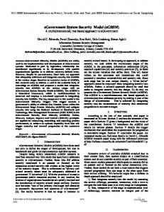
4 Experimental Results For the development of our tool flow we experimented with simple ISCAS’89 benchmarks [12]. Figure 11 shows the RC Schematic Viewer with the 3D-wrapped s400 circuit. The largest box in the middle is the actual die instance and the rest of the circuitry is the wrapper. The WIR instance, the second-largest box, can be found on the left side in the schematic. To the left and to the right of the die instance 3 input and 6 output wrapper cells can be recognized. Even for such a simple test case, the wrapper is a relatively complex structure to create manually.
WIR loading and Scan protocols are different: to select between them we introduce user-defined IEEE 1149.1 instructions. For supporting timing-critical Launch-on-Capture (LOC) and Launchon-Shift (LOS) delay fault tests in addition to Stuck-At (SA), we implement an extra instruction. LOC and SA tests resemble each other in their protocols, hence they can share the same instruction. The protocols for the different operations are shown in Figure 10. In total, there are three IEEE 1149.1 user-defined instructions for using the 3D wrapper: • WIR Program to load the WIR (SelectWIR is high) • LOC for both LOC and SA tests (SelectWIR is low) • LOS for LOS tests (SelectWIR is low)
Figure 11: 3D-wrapped ISCAS’89 s400 (RC Schematic Viewer). For verification of our 3D-DfT tool flow we use a test circuit from TSMC with the following design data: • 65nm CMOS • Functional design Figure 10: IEEE 1149.1 TAP state mapping to WSC.
- 727 functional I/Os - 229,249 stdandard cells (incl. 28,224 flip-flops) - Area 2,070,536μm2 (1,346,636μm2 std. cell area)
To generate WSC signals for different operation from signals available at the IEEE 1149.1 interface and TAP controller, extra logic is needed. In our design flow this logic block (“1149.1-to-1500”
Table 1 shows the die area increase after the various DfT steps,
399
related to the total standard-cell area. The largest area increase (+7.8%) is a result of replacing functional flip-flops with scan flip-flops which contain a multiplexer for selecting between functional/capture and shift operations. This step is required for any die using scan design, including conventional 2D dies; and therefore we do not consider the area overhead of scan-mapping as part of the 3D wrapper area costs. DfT Item
Δ Area
Scan chains 3D Wrapper JTAG Wrapper
+7.8% +1.0% +0.6%
5
Conclusion
This paper presents a DfT architecture for TSV-based 3D-SICs and automation of DfT logic insertion. The architecture enables pre-bond and post-bond die and interconnect testing. The automated insertion of an IEEE 1500-based 3D wrapper is done using script-based extensions for existing EDA tools. Bottom dies can be extended with IEEE 1149.1 to reduce pin-count and to enable board-level interconnect test. We have verified the tool flow using an industrial test case. The wrapper area costs can be estimated for given design parameters and technology; we have shown that it is negligible for realistic designs.
Table 1: DfT area costs. Due to the combination of the design’s relatively small gate area and large number of I/Os, the relative 3D wrapper area of 1.0% is rather large. In fact, this percentage would scale down for realistically-sized designs. To show that, we use the following equation to estimate the 3D wrapper area for larger designs [5]: Aw = fc + i · ic + n · nc ,
Acknowledgements We kindly acknowledge the support of Robert Bakalar, Patrick Gallagher, Sue Genova, Franck Gerome, Patrick Haspel, Leon Palmer, Sanjiv Taneja, Mike Vachon, and Thomas Valind at Cadence Design Systems, Chun-Chuan Chi at IMEC, and Prof. Mladen Berekovic at the Braunschweig University of Technology.
(1)
where fc , ic , and nc are technology-dependent parameters; i and n are the number of functional I/Os and die-internal TAM width, respectively. fc represents a fixed area cost including the WIR; ic is basically the area of one wrapper cell; and nc is roughly the area of two bypass registers (Bypass and Turn) and multiplexers for scan chain concatenation. Other parameters of the functional design, e.g., the number and the length of internal scan chains, have little impact on the wrapper area and hence we neglect them here.
References [1] Philip Garrou, Christopher Bower, and Peter Ramm, editors. Handbook of 3D Integration – Technology and Applications of 3D Integrated Circuits. Wiley-VCH, Weinheim, Germany, August 2008. [2] Geert Van der Plas et al. Design Issues and Considerations for Low-Cost 3-D TSV IC Technology. IEEE Journal of Solid-State Circuits, 46(1):293–307, January 2011.
This area cost model has been verified by an experiment. We wrapped 100 black-boxed designs with different i and n using the 3D wrapper insertion tool, and recorded the wrapper area. The results show that the area has a linear dependence on i and n, as the equation assumes.
[3] IEEE Computer Society. IEEE Std 1500TM -2005, IEEE Standard Testability Method for Embedded Core-based Integrated Circuits. IEEE, New York, NY, USA, August 2005. [4] Francisco da Silva, Teresa McLaurin, and Tom Waayers. The Core Test Wrapper Handbook – Rationale and Application of IEEE Std. 1500TM , volume 35 of Frontiers in Electronics Testing. Springer-Verlag, Boston, MA, USA, 2006.
We calculated the parameters fc , ic , and nc for two different TSMC technology libraries by wrapping three designs with different values of i and n. Table 2 shows the results.
fc ic nc
[5] Erik Jan Marinissen et al. 3D-DfT Architecture for Pre-Bond and Post-Bond Testing. In Proceedings IEEE International Conference on 3D System Integration (3DIC), November 2010. Paper 3B.1.
130nm
65nm
[6] Erik Jan Marinissen. Testing TSV-Based Three-Dimensional Stacked ICs. In Proceedings Design, Automation, and Test in Europe (DATE), pages 1689–1694, March 2010.
1500μm2 50μm2 146μm2
388μm2 14μm2 41μm2
[7] IEEE Computer Society. IEEE Std 1149.1TM -2001, IEEE Standard Test Access Port and Boundary-Scan Architecture. IEEE, New York, NY, USA, June 2001. [8] Rahul Agarwal et al. Cu/Sn Microbumps Interconnect for 3D TSV Chip Stacking. In Electronic Components and Technology Conference (ECTC), pages 858–863, May 2010.
Table 2: Calibrated parameters for different technologies.
[9] Erik Jan Marinissen and Yervant Zorian. Testing 3D Chips Containing Through-Silicon Vias. In Proceedings IEEE International Test Conference (ITC), November 2009. Paper ET1.1.
The accuracy of the equation can be shown by comparing the actual wrapper area for the TSMC test case with the estimated value using the same design parameters: i = 727 and n = 49. The equation predicts an area of 12, 575μm2 ; this is 6% below the actual wrapper area, which is 13, 362μm2 . Using Equation (1) we can estimate the 3D wrapper area for a realistic design and show that the relative wrapper area costs are negligible. For instance, for a die with an area of 50mm2 , i = 2000, and n = 50, the relative area cost of the wrapper would be 0.06%, which is negligible.
[10] Ken Smith et al. Evaluation of TSV and Micro-Bump Probing for Wide I/O Testing. In Proceedings IEEE International Test Conference (ITC), September 2011. Paper 17.2. [11] Krishna Chakravadhanula and Vivek Chickermane. Automating IEEE 1500 Core Test – An EDA Perspective. Design Test of Computers, IEEE, 26(3):6 –15, May 2009. [12] F. Brglez, D. Bryan, and K. Kozminski. Combinational Profiles of Sequential Benchmark Circuits. In Proceedings International Symposium on Circuits and Systems (ISCAS), pages 1924–1934, Portland, OR, May 1989.
400