Automation tools will play an important role in realizing these enhancements. Recent automation tool developments for enhancing surface operation include the ...
Airport Surface Operation Collaborative Automation Concept Victor H. L. Cheng* Optimal Synthesis Inc. Palo Alto, California ABSTRACT Limitation in airport runway throughput naturally constrains traffic capacity. For this reason, the increasing demand on capacity ultimately will require airport expansion to increase the number of runways and associated taxiways. Often the airport expansion plans necessitate an increase in the complexity of surface traffic, leading to a decrease in surface traffic efficiency, which is reflected as an increase in taxi delays. Consequently any concept to increase airport traffic capacity needs to take into account efficiency issues such as taxi delays as well as safety and operator workload issues. This paper introduces a collaborative automation concept being developed under the Surface Operation Automation Research (SOAR) to address some of these issues in a complex airport environment. The concept is enabled by advanced technologies envisioned for the 2020 time frame. It involves surface traffic management (STM) automation to aid tower operation, and flight-deck automation to help execute clearances generated by the STM automation for efficient surface operation. The functions of and integrated operation between these automation components are described, together with an assessment of enabling technologies in communication, navigation, and surveillance. Plans for evaluating the collaborative concept prior to full-scale technology development are discussed.
INTRODUCTION The problem of air traffic growth unmatched by commensurate growth in capacity has been witnessed with substantial peak summer flight delays prior to the 9/11 terrorist act, and well documented and recognized by many concerned parties including the Federal Aviation Administration (FAA) and NASA. In the National Airspace System (NAS) Operational Evolution Plan (OEP) [1, 2], FAA recognizes the capacity problem, and specifically identifies congestion at key airports as one of the domains where the problem is most prominent. As arrival flights descend from cruise to the airport for landing, they transition from the 3-dimensional (3D) space of the Air Route Traffic
*
AIAA Associate Fellow; Principal Scientist.
Control Center (ARTCC) to enter the Terminal Radar Approach Control (TRACON), where the traffic patterns are basically 2D, and subsequently to final approach and landing, where trajectory control is limited to 1D. The funnel effect on the arrival traffic is evident, and the presence of departure traffic further complicates the arrival traffic control. Traffic on the surface reverts back to a 2D pattern composed of runways and taxiways. These observations corroborate the FAA’s identification of airport congestion as a key factor of the NAS capacity problem. In any domain of the NAS, traffic capacity can be viewed as a product of two primary factors: usable space and permissible traffic density, i.e. Capacity = Space × Density . In the surface domain, in particular, the strategy to improve airport capacity by increasing usable surface area is evident from the FAA’s NAS OEP, which includes construction of new runways or extensions at 14 major airports by 2010. In view of landing and departure rate limits imposed by separation requirements, construction of new runways is ultimately inevitable to achieve capacity gain. In addition to the cost of construction, the increase in surface traffic complexity resulting from the airport expansion will incur other indirect costs or penalties that should be taken into consideration. For most major airports, adding runways would produce airport configurations with some runways blocking the traffic between the terminal ramp area and other runways further out. The increased airport complexity implies that there are more taxiway intersections and runway crossings to worry about. Any increase in throughput of the outer runways will lead to a further increase in the need for crossing the inner runways. Furthermore, a similar increase in the throughput of the inner runways reduces the opportunity or time margins for runway crossings to take place.
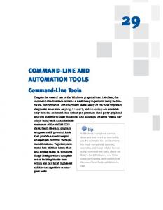
Figure 1 illustrates the relationships between traffic throughput and taxi delay and other penalty factors. The second factor affecting capacity, permissible density, is related to separation requirements: reduced separation allows for increased traffic density, hence higher capacity. The NAS OEP has identified activities for improving traffic efficiency through better use of airspace and reduced separation: deployment of automation to fill gaps in arrival and departure streams, and expanded use of the 3-mile separation standard by
1 American Institute of Aeronautics and Astronautics
reassigning en-route airspace to terminal facilities. Other efforts for reducing separation requirements include the study of wake vortex dissipation characteristics to minimize the need for wake-related separation. Capacity = Space × Density Separation-1 Increases Airport Complexity
Increases Traffic Rate
Decreases ATC Time Margins
Increased ATC Complexity
Penalty on Efficiency
Reduces Effectiveness
Introduces Other Costs
Taxi Delay, Workload, Safety, etc.
Figure 1. Consequences of CapacityEnhancement Efforts
Figure 1 suggests that the increase in airport complexity, increase in traffic rate and decrease in time resources available to air traffic control (ATC) per flight altogether complicate ATC operations. As the operational changes to increase traffic density are meant to improve the operational efficiency, the increased ATC complexity brought forth by the changes would counter the improvement. In order to achieve proportionate increase in throughput from addition of new runways and taxiways, the surface operation often needs to resort to tactics such as grouping flights requiring active-runway crossing to minimize disruption of landing and takeoff traffics. This practice is an example of procedural adaptation to minimize the penalty on operational efficiency in the complex traffic environment, but such changes may in turn lead to an increase in other costs such as taxi delay, workload, safety, etc. The issue of surface traffic efficiency in terms of taxi delays is well recognized. An MIT study reported by Idris et al [3] indicates that among the many factors affecting airport surface traffic flow when the runway is studied as a flow constraint, the factor classified as “other flight landing/departing” stands out as the most prominent one. Since the runway is shared for landing, takeoff, and crossing, these results are consistent with the notion that the taxiing traffic requiring activerunway crossings experiences substantial taxi-delays when the runways are heavily occupied by takeoff and landing traffic. Reference [4] indicates that, for departure traffic, there would be substantial savings by
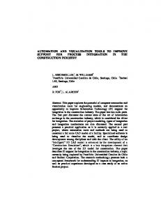
converting runway queuing time into gate delays. It is therefore reasonable to conclude that minimization of unnecessary taxi time would increase savings for both departure and arrival traffic, even if it means more gate holding delays. Serious surface-traffic safety issues already exist in today’s environment. One such issue is the runway incursion problem, and the FAA Runway Incursion Reduction Program (RIRP) [5] studies technologies that can provide improved surveillance information to enhance situation awareness of ATC and the flight crew [6–9]. With active-runway-crossing delays identified as an important factor affecting airport operations, the Dallas – Fort Worth (DFW) Airport Development Plan [10] includes several proposed ideas to ease the impact. One such idea under serious consideration involves construction of “perimeter taxiways” to allow arriving aircraft to taxi in by going around the north and south ends of the other runways, as shown in Figure 2. Such construction will be expensive and will require the aircraft to taxi longer distances around the runways, thus increasing taxi time and fuel consumption, further adding to noise and air pollution. Furthermore, this type of solution may not be practical at other airports where the existing airport layout or land availability may be limiting factors. Other potential solutions should be explored to ease the penalty on traffic efficiency associated with complex airports. North Airfield Perimeter Taxiways
South Airfield Perimeter Taxiways
Figure 2. Perimeter Taxiway Concept Proposed for DFW
The NAS OEP includes plans to address the traffic efficiency issue. Automation tools will play an important role in realizing these enhancements. Recent automation tool developments for enhancing surface operation include the Surface Movement Advisor (SMA) [11], and the Surface Management System (SMS) [12, 13]. This paper presents a collaborative
2 American Institute of Aeronautics and Astronautics
automation concept for enhancing airport surface operations, known as the Surface Operation Automation Research (SOAR) concept [14]. The goal of this concept is to employ automation to minimize the penalty on efficiency associated with the complex airport traffic, striking a good balance in efficiency among arrival, departure, and surface traffics.
OVERVIEW OF SOAR CONCEPT The SOAR concept introduces advanced automation to the two main environments responsible for surface operation: the ground control environment and the flight deck. The automation technologies will deliver maximal performance when these two environments can be tightly integrated in a Centralized DecisionMaking, Distributed Control (CDDC) paradigm. The surface traffic management (STM) automation system will provide the centralized decision-making functionality. It will base its decisions on surveillance data, flight plans and Airline Operational Control (AOC) requirements, to generate time-based taxi routes for optimum traffic efficiency. Advanced data-link will enable the issuance of complex taxi clearances for the flights to taxi according to the desired time-controlled taxi routes. An STM-automation concept, known as the Ground-Operation Situation Awareness and Flow Efficiency (GO-SAFE) system [15], will serve as the foundation for building the STM automation system envisioned by the SOAR concept.
automation component of the SOAR concept. Through this CDDC paradigm, the SOAR concept capitalizes on the integrated operation of the GO-SAFE and FARGO systems to enable ATC and the flight crew in achieving surface operations that balances the optimization of both airport capacity, in terms of maximizing arrival/departure efficiency, and surface traffic efficiency, in terms of minimizing taxi delay. The time frame addressed by the SOAR concept is 2020. Within this time frame, evolution of NAS is assumed to be consistent with the OEP, the FAA NAS Architecture [17], and the RTCA NAS concept document [18]. Figure 3 contains a high-level block diagram of the SOAR concept. Key operational functions of the SOAR concept are divided into three categories corresponding to the STM automation system, the flight-deck automation system, and the integrated operation of both systems. These functions are discussed in the subsequent sections, followed by discussions of enabling technologies in communication, navigation, and surveillance (CNS), and future plans for evaluating the SOAR concept.
STM AUTOMATION FUNCTIONS The STM automation component of SOAR builds upon the GO-SAFE system documented in [15]. This system has undergone limited development with a preliminary set of capabilities, but which has not been subject to any evaluation with human subjects. The following subsections cover the desired capabilities of the GOSAFE system, with reference to its existing experimental implementation where appropriate to illustrate its preliminary capabilities.
Communications
The flight-deck automation systems in the aircraft participating in the surface operation will collectively provide the distributed control of the overall traffic system in a collaborative manner. Advanced automation technologies will provide auto-taxi capabilities or automation aids to the pilots for performing precision taxi to achieve the time-controlled GO-SAFE User Interface taxi routes issued as clearances by ground control. New As with most advanced automation systems, an operation procedures will need to be defined for effective user interface is essential for the GO-SAFE carrying out data-linked clearances, and for automatic loading of the clearances into the Air Traffic Service aircraft’s flight management systems Provider (FMS). A previous effort has demonstrated with computer simulations that advanced Flight Plans & Acknowledgments Flight nonlinear control methods can be deployed Traffic Crew Control Aircraft to control the aircraft’s taxi operation to Aircraft Control Clearances Dynamics track very precisely defined time- GO-SAFE FARGO constrained taxi routes, even in the highly dynamic environment of performing activeNavigation Data Navigation runway crossing immediately after the aircraft has landed on an adjacent runway Surveillance Data [16]. The Flight-deck Automation for Surveillance Other Reliable Ground Operation (FARGO) Aircraft system represents further development of Figure 3. Top-Level Block Diagram of the SOAR Concept this idea to achieve the flight-deck
3 American Institute of Aeronautics and Astronautics
system to assist with various functions: •
Access intelligent routeplanning functions and resulting surface-operation advisories
•
Manually adjust automationgenerated advisories
•
Issue clearances via data link to flights
•
Monitor traffic, including surveillance of individual flights and ground vehicles, flight compliance with clearances, and traffic statistical data
Node-Traffic Load Graphs
Conflict Information
Node-Traffic Time Lines Plan-View Display
Clearance/Status
The experimental GO-SAFE Figure 4. Overview of Experimental GO-SAFE Graphical User Interface system reported in [15] included a graphical user interface (GUI) for multiple time lines on another, and multiple load graphs the user to perform these functions. Figure 4 illustrates on a third, etc. the various graphical components in the experimental GO-SAFE GUI. It has five panes, the most prominent Planning Functions of which is the plan-view display, which in this A fundamental planning requirement of GO-SAFE is example shows the DFW airport layout. It shows the the capability to generate advisories for efficient, aircraft location based on surveillance data. It allows conflict-free taxi routes for the whole surface traffic. data tags to be defined and formatted for the flights. The original experimental GO-SAFE system [15] The Clearance Manager discussed below can use these implemented an automatic taxi-route generation data tags for conveying clearance status information to capability based on Dynamic Programming using the the ground controller. Dijkstra’s algorithm [19, 20] for route optimization. In The time-line display to the left of the plan-view anticipation of future enhancements and addition of display shows the predicted time instants at which the new route-generation schemes developed by others, flights will cross user-selected locations, which are including those developed based on preferences currently restricted to nodes as defined by the originating from ATC practices, the object-oriented intersections of the taxiways/runways. Above the plansoftware design of GO-SAFE includes a route manager view display are traffic load graphs, which show the for maintaining multiple schemes and their resulting predicted traffic density across user-selected locations. routes. The Ground-Operation Decision Support Future enhancements may include aggregate load (GODS) tool described in [15] also includes an graphs that would provide more relevant information to automatic de-conflicting capability to ensure conflictthe controller for predicting surface traffic congestions. free taxi routes, and a runway usage sequencing and scheduling capability to enhance surface traffic Conflict information on planned routes is displayed in efficiency. table form in the upper-right corner. In cases where the user chooses to use route-generation techniques that do Future GO-SAFE technology envisioned by SOAR will not guarantee conflict-free routes, it allows the include route generation capabilities to simultaneously controller to identify conflicts and resolve them optimize taxi routes for multiple flights. An integrated manually or to resolve them using other de-conflicting approach will optimally allocate taxiways and runways functions provided by GO-SAFE. The bottom of the as resources for conflict-free taxi routes. Techniques GUI displays clearances and advisories for flights being considered include extension of Dynamic selected by the user, and the status of any issued Programming to simultaneously plan taxi routes with a clearances. Each of the panels of the GUI in Figure 4 is variable, moving time window to handle flights that resizable, scalable, and scrollable, making it possible to may interfere with one another. Another approach configure multiple monitors to display different being considered employs genetic techniques. information, e.g. plan-view display on one monitor, Specifically, the Genetic Search Toolbox™ [21] is an
4 American Institute of Aeronautics and Astronautics
Optimal Synthesis Inc. (OSI) product that provides functionality in Genetic Algorithms (GA) [22, 23] and Genetic Programming (GP) [24]. Techniques based on both of these genetic techniques had been studied previously in a runway assignment and scheduling problem for arrival traffic [25].
controllers can then use the planning functions to speed up the recovery of orderly and efficient traffic. GOSAFE provides the traffic monitor functions discussed below to help the controllers detect off-nominal conditions, and the planning functions discussed in the previous section should provide the dynamic replanning capability.
Traffic Control Functions
An information display function will make the output from the planning functions available to the air traffic controllers at the control tower. New GUI functions should replace conventional flight strips to ease handoff of flights between controllers, assure data integrity, and enhance information availability on an as-needed basis. Text and numeric data can be displayed in tabular form as a natural evolution of the flight-strip paradigm, or made available on demand when attention is called to a flight via the GUI. Information such as taxi-route advisory can be displayed graphically. The controllers always have the freedom not to use any advisory from GO-SAFE, but they can also benefit from the capability to make adjustments to the advisories. In its simplest form this can be accomplished through text editing, which, however, is not very practical if the process requires significant attention from the controllers. User-friendly input modes will help alleviate this problem. The Taxi Route Assignment and Previsualization (TRAP) tool discussed in [15] is an example for convenient modification of taxi routes using popular GUI notions. With simple point, click and drag, the user can quickly change the taxi destination of a flight, modify a segment of the taxi route, or impose timing constraints. The Clearance Manager function allows the GO-SAFE advisories to be converted to clearances for issuing to the flights. It is unlikely that the time-based taxi-route advisories from GO-SAFE can be effectively converted to verbal clearances. It is therefore reasonable to assume that the taxi routes will be converted to clearances that are transmitted to the flight deck via data link. As the clearances are communicated via data link, it makes sense to consider also clearance acknowledgments to be handled via data link, making it a simple matter for the Clearance Manager to keep track of the clearance status. Different status conditions can be conveyed to the controller via the data tags in the GUI, or other conventions such as changes in the flight icons or their colors. An automation system has to allow the controllers to handle unanticipated events as well as perform normal operations. In off-nominal situations, the controllers need to first detect the unexpected event and react accordingly to stay away from catastrophes. After safety concerns have been adequately addressed, the
Traffic Monitor Functions
The automation functions of GO-SAFE can enhance the situational awareness of the controllers. The GUI discussed above already provides a display for surveillance of the surface traffic, and the GroundOperation Prediction And Statistics Tool (GO-PAST) discussed in [15] provides predicted traffic data in the form of load graphs and time lines to help controllers anticipate traffic demand. Underneath the GUI, automation functions can monitor the traffic and alert the controllers of impending problems. Other automation systems such as the Airport Movement Area Safety System (AMASS) may extrapolate the estimated aircraft states to predict conflicts. If taxi routes generated by GO-SAFE are designed to be conflict-free, then any real-world conflicts will necessarily mean that the aircraft has deviated from the taxi route associated with the delivered clearance beyond the allowable margin. This greatly simplifies the real-time conflict-detection procedure by shifting the conflict-detection responsibility to a clearance-conformance monitoring function. As the Clearance Manager keeps track of the status of clearances issued to the flights, a Conformance Monitor function can combine this information with surveillance data to monitor the state of the flights to ensure that they are in conformance with the clearances. As long as the flights are all in conformance with the clearances, which are assured to be conflict-free by the automatic conflict-resolution function of GO-SAFE, there is no danger of conflicts of any kind, including runway incursions, taxiing on the wrong taxiway, or accidents/incidents similar to some of the recent notorious events of taking off from the wrong runway [26] or even from a taxiway [27]. Whenever the Conformance Monitor detects sufficient deviation by a flight from its clearance beyond allowable margins, it should be cause for alarm, and the controller should be alerted. Furthermore, only under such situation will GO-SAFE need to search for potential conflict with other flights. This systematic process will simplify the runway incursion and other vehicle conflict problems.
FLIGHT-DECK AUTOMATION FUNCTIONS To fully realize the potential benefits of the SOAR concept, the aircraft should be able to deliver high-
5 American Institute of Aeronautics and Astronautics
precision taxi performance that GO-SAFE can count on to deliver highly efficient traffic. The FARGO concept will provide the necessary functionality to enable collaborative taxi control with two main components: •
Auto-taxi function for precisely controlling the aircraft taxi to accomplish taxi clearances, including time-based clearances
•
Pilot interface to allow the pilots to perform precision-taxi in the far-term by allowing fully automatic taxi, and in the near-term by using control signals generated by the auto-taxi function to direct manual control
These two main FARGO functions are shown in the general aircraft-control block diagram of Figure 5, and are discussed in more detail in the following subsections. FARGO Auto-Taxi Function
A previous feasibility study has verified that, with the synthesis of a nonlinear guidance and control system in a simulation based on a B-737 model, the aircraft can achieve high-precision taxi control [16]. The study applied a form of feedback linearization [28–31] to design the Auto-Taxi Control function of Figure 5. That study contained various runway-crossing analyses, including a series of analyses to study high-precision taxi control for taxiing continuously immediately after landing to cross an adjacent runway with the tightest of time margin. The results showed that the guidance and control function was able to perform high-precision taxi operations, limited only by the accuracy of the navigation system that provides the position and velocity estimates of the vehicle. With current technology on differential Global Positioning System (DGPS) and the recent decision by the US to release GPS P-code for public use, the tracking should be accurate to the order of a meter. If properly deployed, such precision-taxi capability will allow efficient traffic planned by GO-SAFE to be realized. Furthermore, it will help to cut down on the need for the infamous land and hold-short operations (LAHSO), which pose a major concern of runway incursion possibilities.
Taxi Clearance
The Auto-Taxi Control subsystem of Figure 5 also includes a guidance function for generating a reference trajectory as a precursor to the control signal. For a near-term FARGO concept without a full auto-taxi capability, the reference trajectory and/or the resulting control signal can be provided as the Control Advisory to the pilot for manual taxi control, as depicted in the block diagram. Despite the promising results from [16] to support precision taxi, the analyses also revealed the need for a more robust control scheme to handle perturbed situations, such as touching down beyond the anticipated mark. In the scenario where a flight misses the anticipated touch-down point, the landing speed will be too high, causing a deceleration prohibitively high for passenger comfort in order to satisfy the postlanding taxi constraints. For situations of this nature, the FARGO concept needs to incorporate corrective actions to determine a new taxi profile to bring the deceleration within acceptable limits, and development of such capabilities is ongoing. FARGO Pilot Interface
Notwithstanding the possibility of an auto-land autotaxi capability in the far term, a more realistic implementation of the envisioned FARGO will involve pilot control assisted by some sort of flight director to provide information for tracking the reference trajectory. Traditionally a cockpit display with a speed bug serves well as a pilot interface for speed control when constant airspeed is expected, as in the cases of cruise, climb, and descent. In the case of roll out and turn off after landing, the control involves a deceleration segment followed possibly by a constantspeed taxi segment. It is obvious that such a display scheme may not be appropriate during the deceleration phase since the speed is constantly decreasing and a time-varying speed bug may not be the proper choice. In addition, deviation of the speed from the predetermined profile will require consequential corrections in order to achieve the time window cleared by ATC.
An approach to the pilot interface problem is being explored based on the definition of a phantom vehicle derived FARGO from the reference trajectory Control Advisory Flight Display Crew generated by FARGO. The idea Autois similar to that of highway Control Aircraft Taxi driving, where one car length is Actuation Dynamics Control Control Signal normally recommended between the own vehicle and the one Estimated Vehicle State ahead for every 10 m.p.h. of Navigation speed. An easier rule of thumb for providing safe driving Figure 5. General Block Diagram of Aircraft Control with FARGO Concept 6 American Institute of Aeronautics and Astronautics
separation is to stay 3 sec behind the vehicle ahead. This rule is consistent with natural human behavior for safety that one would leave more room as the car speeds up. This analogy is used to define a phantom, “pace vehicle” ahead of the aircraft to control its taxi speed and Figure 6. Relationship of Phantom, Pace Vehicle with Own Vehicle reference path. As shown in the conceptual illustration of Figure Since the efficient traffic envisioned by SOAR will 6, the pace vehicle leads the own vehicle by a time require issuance of clearances that contain taxi routes interval of τ. The position of the pace vehicle is with tight time constraints, it will be difficult to issue adjusted dynamically as a function of the own-ship such clearances with today’s voice communication and reference trajectory. To determine the pace-vehicle thus the use of data-link seems inevitable. However, trajectory, the following need to be taken into account: experience in the past with data-link experiments has •
Own-ship reference trajectory
•
Duration τ, which should be designed based on evaluation feedback from subject experts
•
Acceleration/deceleration
•
Stop/go events
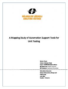
This pilot interface can be suitably integrated with the Taxiway Navigation and Situation Awareness (TNASA) system [32] developed by NASA. The TNASA system has three components [33–35]: a headdown moving map in the form of a track-up airport surface display showing own-ship, traffic and graphical route guidance; a head-up display (HUD) with scenelinked symbology to provide route/taxi information; and a 3D Audio Ground Collision Avoidance Warning (GCAW) system to provide spatially localized auditory traffic alerts. Figure 7 shows the cockpit with the TNASA displays, where the HUD is the display of choice for the phantom/pace vehicle symbology, as constant pilot attention out the window is crucial for safe taxi operations. A 3D perspective symbol of the vehicle can be added to the T-NASA HUD symbology, and additional symbols can be designed to show whether the own vehicle is too far behind or ahead relative to the pace vehicle. Another advantage of the HUD-based display is that it helps to reduce pilot error in misreading airport layout.
shown that there are many issues associated with datalinked clearances. On the controller side, the controller can no longer issue a clearance and expect an immediate acknowledgment. On the cockpit side, the data-linked clearance may need to be read out to ensure that both pilot and co-pilot agree on its content. Moreover, visual attention has to be re-directed from the crew’s aircraft-control function to reading the clearance, followed by acknowledging it with key strokes on the control console. Since a clearance involving the complete taxi route with time constraints is quite complex, the clearance will most likely be sent as a pre-clearance to allow the crew ample time to understand it. On the other hand, route information included in the data-linked clearances can be conveniently loaded into the FMS for use by the FARGO function. The SOAR concept will also impact surface operational procedures in other ways. The current STM practice
OPERATIONAL INTEGRATION OF AUTOMATION FUNCTIONS In determining the success of deploying advanced automation systems, often the automation technologies are secondary to operational issues. With human in the loop and lives on the line, machinery reliability alone is not sufficient for validating the safety of the system. Various operational issues must be addressed for the SOAR concept to be successfully realized.
Figure 7. Taxiway Navigation And Situation Awareness System (T-NASA) (Source [32])
7 American Institute of Aeronautics and Astronautics
for controlling the landing traffic requires a flight to be handed off by the arrival controller to the ground controller after landing. Since the SOAR concept will involve clearances issued via data link to contain the complete taxi route from landing to entering the ramp area, this means that the taxi clearances given prior to landing may eliminate the controller handoff. The operational functions between STM and the flight deck under the SOAR concept are summarized below and in Figure 8. •
GO-SAFE displays advisories to air traffic service provider (ATSP)
•
ATSP issues clearance to flight deck via data link
•
FARGO displays clearance information to flight crew
•
Flight crew responds to clearance
•
Flight crew interacts with FARGO to execute control of aircraft
•
GO-SAFE monitors aircraft compliance with clearance
•
ATSP responds to GO-SAFE alerts
The operational functions requirements for these functions will be assessed for the SOAR concept. This will lead to definitions of the roles and responsibilities of the operators, as well as the automation systems. Conflict-Free Taxi Routes
STM
Command & Control
Surveillance
Navigation
Aircraft
Visual
FARGO
Control
Display Voice Clearance
Clearance & Route Display
ATSP
Data-Linked Clearance
Flight Deck
Command
Advisories, Surveillance & Alerts Display
GO-SAFE
Clearance Acknowledgment
surveillance for feedback to STM automation to deliver well-balanced airport capacity and surface traffic efficiency, and to the flight deck for improved situational awareness of nearby traffic. Advanced CNS technologies currently being considered by the FAA and ICAO are assumed to be available. Other technologies that may benefit the SOAR concept include weather prediction that can augment the information used by the SOAR automation functions, and wake vortex prediction technologies such as those pursued by the Aircraft Vortex Spacing System (AVOSS) [36], as they will have an impact on the separation requirements for landing, takeoff, and possibly active-runway crossing operations. The SOAR concept will also benefit from these and other automation systems: SMS [12, 13], and Center/TRACON Automation System (CTAS) [37] with its various tools, including the Traffic Management Advisor (TMA) [38], Final Approach Spacing Tool (FAST) [38], Collaborative Arrival Planner (CAP) [40], and the Expedite Departure Path (EDP) tool [41]
Much of the advancement of CNS technologies is included in the NAS modernization plan [17], which is implemented in three phases through 2015, well ahead of the time frame of 2020 targeted by the SOAR concept. These technologies are summarized in the following subsections. Communication
The NAS modernization plan include the following key communications technologies: •
Controller-pilot data link communications (CPDLC) — introduces data exchange between controllers and pilots to reduce voice-channel congestion. CPDLC will first be available using VHF digital link (VDL) Mode-2 ground and airborne equipment.
•
Integrated ground telecommunications infrastructure — a digital infrastructure to provide integrated voice, data, and video connectivity for air traffic control operations.
•
Digital voice and data communications via digital radios provided by the next generation air/ground communications (NEXCOM) program — introduces VDL Mode-3 ground and airborne radios to improve spectrum utilization.
Flight Crew
Clearance Acknowledgment
Figure 8. Integrated Operational Functions Between STM and Flight Deck
ENABLING TECHNOLOGIES The collaborative automation systems of the SOAR concept rely on advanced CNS technologies: timely communication of precise information between the automation systems and operators; accurate navigation for feedback to execute aircraft control; and effective
Initially, aircraft equipped with traffic information service (TIS) avionics will be able to receive a display of nearby traffic via the Mode-S data link, provided by Mode-S radar. Tower data link service will also be available. After NEXCOM digital radios are installed
8 American Institute of Aeronautics and Astronautics
and operating in all high and super-high en route sectors, they will be installed in selected high-density terminals and their associated low en route sectors in the 2008–2015 time frame. At this point, NAS-wide data link services will be available to provide: •
Expanded flight information services (FIS) to provide pilots with information on airspace and airport conditions
•
Expanded TIS to provide information to the pilot
•
Expanded CPDLC to provide the full Build 3 message set.
increased
traffic
Future technology development for the SOAR concept will consider the use of CPDLC to effect the delivery of GO-SAFE clearances. Navigation
The NAS modernization plan contains the following steps in transitioning to satellite-based navigation: •
Use of the global positioning system (GPS) for en route/terminal navigation and non-precision approaches provided that another navigation system is onboard the aircraft
•
Deployment of the wide area augmentation system (WAAS) to provide en route/terminal navigation and Category (CAT) I precision approaches
•
Deployment of the local area augmentation system (LAAS) to augment GPS for CAT I/II/III precision approaches.
By 2007, LAAS will have been deployed at approximately 150 airports, providing CAT I, II, and III precision approach capability to all suitably equipped runways. LAAS will also provide the airport surface navigation signals needed for precise taxiing in lowvisibility conditions. Through 2015, the NAS modernizations call for continued transition away from ground-based navigation commensurate with WAAS and LAAS avionics equipage and performance. New GPS satellites will provide additional civilian frequencies for increased reliability. At this point, GPS will definitely be able to provide adequate navigation performance for implementing the FARGO automation. Surveillance
Throughout the evolution to Automatic Dependent Surveillance (ADS), surveillance and separation services in a mixed equipage environment will be provided. This means the FAA will continue to rely on aircraft transponders to verify aircraft position. New digital terminal radars (ASR-11) will provide improved
aircraft and weather detection and aircraft tracking. As users equip with ADS-Broadcast (ADS-B), secondary surveillance radar will be upgraded to request aircraft position information from ADS-B avionics to improve surveillance tracking. Installation of ADS ground equipment for airport surveillance is planned to start at high-activity airports by the 2007 time frame. By 2015, the installation of ADS ground systems is expected to be complete to serve all domestic airspace. A multi-purpose airport radar (MPAR) for terminal airspace, which incorporates primary radar, secondary surveillance radar, and Doppler weather radar capabilities, will start development for installation. Secondary surveillance radars will continue in service throughout the NAS. This will enable aircraft to continue using transponders or transition to ADS-B. Secondary surveillance radars also ensure that full surveillance services can continue in the event there is difficulty with GPS or individual ADS-B avionics. Using WAAS and LAAS as references, ADS-B avionics and cockpit displays may enable aircraft surface operations to be conducted in reduced visibility conditions. The NAS-wide data link will be used to provide TIS information. The recent FAA decision on the ADS-B link architecture for use in the NAS represents a significant step towards the widespread adoption of ADS-B [42]. The decision has selected two ADS-B technologies for use in the NAS: •
1090 MHz Extended Squitter (1090ES) for aircraft that fly in high-altitude airspace
•
Universal Access Transceiver (UAT) for generalaviation aircraft that are not capable of highaltitude operations
Interoperability between these links will be provided within the coverage of the ground ADS-B infrastructure using the multilink gateway service provided via the TIS-Broadcast (TIS-B) uplink [43, 44]. TIS-B is also used to provide ADS-B-compliant reports on aircraft that are not transmitting ADS-B information [45]. GO-SAFE operation requires state-of-the-art surveillance that provides not only vehicle positions, but also aircraft identification to carry out its route generation functions. These requirements are satisfied with the availability of ADS-B and TIS-B. The nearterm surveillance tools Airport Surface Detection Equipment (ASDE) and Airport Target Identification System (ATIDS) can complement the ADS-B and TISB solutions, both to augment or to serve as backup solutions. The main limitations for the ASDE-3 system, as for all primary sensors, are multi-path signal returns and the lack of target identification. Surveillance data used by GO-SAFE need to include at
9 American Institute of Aeronautics and Astronautics
least position information with proper identification of the vehicles being controlled; consequently raw ASDE3 data will be of little use to GO-SAFE. The data needs to be tagged by additional systems such as those being considered for ATIDS. The modern ASDE-X system [46] provides the ability to identify aircraft through the use of transponder multilateration and ADS-B sensors. It can provide position and identity information on any vehicle equipped with the proper transponder, and at least position information on vehicles that are not equipped. This information can then be shared with all ADS-B equipped systems through the TIS-B system, and hence made available to GO-SAFE.
the airport users is minimized. Although maximizing runway throughput will conceptually allow departure traffic to take off sooner and arrival traffic to land sooner, the added taxi time prior to takeoff or after landing due to surface traffic holdup can easily reverse the time savings. Hence, to properly account for the benefits of a capacity-enhancement concept, the airport capacity in terms of arrival-departure throughput needs to be balanced with surface traffic efficiency in terms of taxi delay. To assess the performance of an advanced concept, one can study the increase in capacity corresponding to a fixed average time delay as suggested in Figure 9 [50].
EVALUATION PLANS
In practice, the achievable capacity at the airport may be substantially lower than the ideal capacity due to inefficiency, much of which is caused by interference among the traffic. A notable example is the increased number of active-runway crossings resulting from increased traffic and airport expansion. To bring the achievable capacity close to the ideal capacity, ATC operation can minimize the impact of active-runway crossings on takeoff and landing operations by minimizing the total time taken up by runway-crossing activities, e.g. by queuing up the flights that require crossing and clearing them to cross as a batch. The side effect is inevitably the increase in taxi delay when the flights have to line up and wait for a large enough group to form before crossing. Referring back to Figure 1, this represents a tradeoff between the two efficiency factors: •
Reduction in achievable traffic rate, a penalty on arrival/departure efficiency
•
Increase in taxi delay, a penalty on surface traffic efficiency
Benefits resulting from capacity-related concepts will largely consist of cost savings to current and future airport users associated with reduced time spent in the airport system [49]. With this in mind, the evaluation of a capacity-enhancement concept should not be looking at the allowable peak traffic rate alone, since this will not necessarily mean that the travel time for
Current
Enhanced Concept
Average Delay
For a given airport layout, the product of the number of runways with the maximum traffic rate per runway under ideal situations constitutes an upper bound on the total traffic capacity of the airport. This upper bound can be considered to be the “ideal” capacity, which can be described as Pareto frontiers [3, 47, 48]. The Pareto frontier of an airport configuration describes the maximum capacity as a tradeoff between arrival and departure rates. It does not account for any capacity loss due to surface operation or other factors.
Effective Capacity Gain
Effective Capacity Figure 9. Increase in Effective Capacity for Given Average Taxi Delay
One can also use the taxi time to define a surface traffic efficiency metric: Surface Traffic Efficiency =
∑ Nominal Taxi Time ∑ Actual Taxi Time
With this metric, the tradeoff between airport capacity and surface traffic efficiency can be illustrated by the relationship suggested in Figure 10. Enhancement in surface traffic efficiency also has effects on other factors such as operator workload and safety. Evaluation of the SOAR concept will need to address all these factors. The NASA Virtual Airspace Modeling and Simulation (VAMS) project is currently providing support for study of the SOAR concept. The program plan includes several evaluation activities in the next few years. An evaluation of the concept is planned for 2003 by OSI, the concept originator, as an in-house activity. This is described as the High-Fidelity Surface Domain Evaluation in Figure 11. This evaluation will be based on an experimental implementation of GO-SAFE and a computer simulation of the surface traffic. It will assess the
10 American Institute of Aeronautics and Astronautics
Surface Traffic Efficiency
capacity/efficiency tradeoff, and compare the results with those obtained from a model representing current operations without the benefit of the automation systems.
1
Enhanced Concept Current
of the SOAR concept on the TRACON traffic for propagating the effects to the NAS-wide model. It is hoped that after the 2004 experiments, resources will be available to perform a Real-Time Human-inthe-Loop Evaluation. This type of experiments will involve human subjects in realistic cockpit simulators as well as control tower simulators. The experiments will be useful for assessing roles and responsibilities of operators and automation systems, human performance and workload, effectiveness of user interfaces, operational procedures, including those required for handling unexpected events.
CONCLUDING REMARKS
0
Effective Capacity
Figure 10. Improvement in Tradeoff Between Surface Traffic Efficiency and Airport Capacity
Planned for 2004 is an evaluation to be performed at NASA Ames Research Center using the Airspace Concept Evaluation System (ACES) [51] to assess the NAS-wide impact of the SOAR concept. This activity is described as the Low-Fidelity NAS-Wide Assessment in Figure 11. If possible, an intermediate experiment — Mid-Fidelity Terminal Traffic Impact Assessment — will be performed to capture the impact
Limitation in airport runway throughput naturally constrains traffic capacity. For this reason, attempts to increase capacity ultimately will require airport expansion to increase the number of runways and associated taxiways. Often the airport expansion plans cause an unavoidable increase in the complexity of surface traffic, affecting adversely the surface traffic efficiency, and ultimately holding back some of the potential benefits. This paper has presented the Surface Operation Automation Research (SOAR) that explores the use of collaborative automation systems to enhance surface operation performance in a complex airport environment. The Ground-Operation Situation Awareness and Flow Efficiency (GO-SAFE) system provides surface traffic management automation to help Low-Fidelity NAS-Wide Assessment
Real-Time Human-in-the-Loop Evaluation Human Performance
High-Fidelity Surface Domain Evaluation Procedures GO-SAFE ATC
Environment
Communications
Surveillance
FARGO Pilot Navigation
Capacity
Safety
Efficiency
Mid-Fidelity Terminal Traffic Impact Assessment
Figure 11. Evaluation Options for SOAR Concept
11 American Institute of Aeronautics and Astronautics
the tower controllers plan and deliver more-efficient taxi traffic, while the Flight-deck Automation for Reliable Ground Operation (FARGO) provides aircraft control automation to help the pilots execute the highprecision taxi clearances desired by the GO-SAFE system. Functions for these two collaborative automation systems are discussed, along with issues associated with operational integration of these systems. Relying on advanced communication, navigation, and surveillance (CNS) technologies, these automation systems also provide enhanced situational awareness to the respective operators for detecting and responding to unexpected events. The availability of the requisite CNS technologies is expected, as envisioned by the FAA’s National Airspace System modernization plan. Several evaluations are planned for the SOAR concept in the near future, ranging from computer simulations for evaluating its benefits in the surface domain, to assessment of its impact to the NAS. The planned SOAR activities are limited to studying the feasibility and benefits of the SOAR concept. Additional future efforts will be required for full-scale development of the automation technologies for realizing the SOAR concept.
ACKNOWLEDGMENT Study of the SOAR concept is currently being supported by NASA under Contract No. NAS2-02073. The development of the experimental GO-SAFE system was supported in part by NASA under Contract No. NAS2-99055. The study on aircraft precision taxi was supported in part by NASA under Contract No. NAS298057.
REFERENCES [1] National Airspace System Operational Evolution Plan, Version 3.0, Federal Aviation Administration, June 2001. [2] National Airspace System Operational Evolution Plan, Version 4.0, Federal Aviation Administration, December 2001. [3] Idris, H. R., B. Delcaire, I. Anagnostakis, W. D. Hall, J. P. Clarke, R. J. Hansman, E. Feron, and A. R. Odoni, “Observations of Departure Processes at Logan Airport to Support the Development of Departure Planning Tools,” 2nd USA/Europe Air Traffic Management R&D Seminar, Orlando, FL, December 1–4, 1998. [4] Pujet, N., B. Delcaire, and E. Feron, “InputOutput Modeling and Control of the Departure Process of Congested Airports,” Proceedings of
the AIAA Guidance, Navigation, and Control Conference, Portland, OR, August 9–11, 1999, pp. 1835–1852.
[5] Capezzuto, V., D. Olster, M. Curry, and S. L. Pendergast, “Runway Incursion Reduction Program (RIRP) Surveillance System, NASA/FAA Atlanta Demonstration,” Proceedings of the IEEE/AIAA 17th Digital Avionics Systems Conference, Bellevue, WA, Oct. 31–Nov. 7, 1998, Paper F31. [6] Castaldo, R., “Positive Identification of Aircraft on Surface Movement Areas — Results of FAA Trials,” Air Traffic Control Technologies II, Orlando, FL, April 10–11, 1996, SPIE Proceedings Vol. 2737, pp. 134–142. [7] Evers, C., R. Cassel, and D. Lee, “Analysis of ADS-B, ASDE-3 and Multilaterlation Surveillance Performance — NASA Atlanta Demonstration,” Proceedings of the IEEE/AIAA 17th Digital Avionics Systems Conference, Bellevue, WA, Oct. 31–Nov. 7, 1998, Paper F33. [8] Edwards V., and C. Evers, “Loop Technology (LOT) as an Alternative Surface Surveillance System,” Proceedings of the IEEE/AIAA 17th Digital Avionics Systems Conference, Bellevue, WA, Oct. 31–Nov. 7, 1998, Paper F45. [9] Hicok D. S., and D. Lee, “Application of ADS-B for Airport Surface Surveillance Proceedings of the IEEE/AIAA 17th Digital Avionics Systems Conference, Bellevue, WA, Oct. 31–Nov. 7, 1998, Paper F34. [10] Airport Development Plan Update — Dallas/Fort Worth International Airport, Dallas/Fort Worth International Airport Board, December 1997. [11] Glass, B. J., “Automated Data Exchange and Fusion for Airport Surface Traffic Management,” AIAA-97-3679. [12] Brinton, C., J. Krozel, B. Capozzi, and S. Atkins, “Improved Taxi Prediction Algorithms for the Surface Management System,” Proceedings of the AIAA Guidance, Navigation, and Control Conference, Monterey, CA, August 5–8, 2002, Paper AIAA 2002-4857. [13] Atkins, S., C. Brinton, and D. Walton, “Functionalities, Displays, and Concept of Use for the Surface Management System,” Proceedings of the 21st Digital Avionics Systems Conference, Irvine, CA, October 27–31, 2002, Paper 1.D.6. [14] V.H.L. Cheng, “Collaborative Automation Systems for Enhancing Airport Surface Traffic Efficiency and Safety,” Proceedings of the 21st
12 American Institute of Aeronautics and Astronautics
IEEE/AIAA Digital Avionics Systems Conference, Irvine, CA, October 29–31, 2002.
[15] Cheng, V. H. L., and D. C. Foyle, “Automation Tools for Enhancing Ground-Operation Situation Awareness and Flow Efficiency,” Proceedings of the AIAA Guidance, Navigation, and Control Conference, Monterey, CA, August 5–8, 2002. [16] Cheng, V. H. L., V. Sharma, and D. C. Foyle, “Study of Aircraft Taxi Performance for Enhancing Airport Surface Traffic Control,” IEEE Transactions on Intelligent Transportation Systems, Vol. 2, No. 2, June 2001. [17] National Airspace System Architecture Version 4.0, Federal Aviation Administration, January 1999. [18] Government and Industry Guidelines and Concepts: NAS Analysis and Redesign, Prepared by SC-192, RTCA, December 14, 2000. [19] Ambainis, A., A. C. Berg, and B. J. Diament, The Influence of Caches on the Performance of Algorithms, web site: http://www.cs.berkeley.edu/~aberg/classes/cs252/ project/gama/fw3.html. [20] Preiss, B. R., Data Structures and Algorithms with Object-Oriented Design Patterns in C++, web site: http://www.pads.uwaterloo.ca/Bruno.Preiss/books /opus4/html/page566.html. [21] Genetic Search Toolbox™ User’s Optimal Synthesis Inc., 1998–2002.
Manual,
[22] Holland, J. H., Adaptation in Natural and Artificial Systems, Cambridge, MA: The MIT Press, 1993. [23] Goldberg, D. E., Genetic Algorithms, Reading, MA: Addison-Wesley, 1989. [24] Koza, J. R., Genetic Programming, Cambridge, MA: The MIT Press, 1992. [25] Cheng, V. H. L., L. S. Crawford, and P. K. Menon, “Air Traffic Control Using Genetic Search Techniques,” Proceedings of the 1999 IEEE International Conference on Control Applications, Kohala Coast, HI, August 22–27, 1999, pp. 249–254. [26] Fiorino, F., “SIA Flight 006 Viewed as ‘Aviation System Failure’,” Aviation Week & Space Technology, May 6, 2002, p. 42–43. [27] Croft, J., “China Airlines Take-Off Blunder Aviation Week & Space Investigated,” Technology, February 4, 2002, p. 48.
[28] Cheng, V. H. L., and T. Lam, “Automatic Guidance and Control Laws for Helicopter Obstacle Avoidance,” AIAA Journal of Guidance, Control, and Dynamics, Vol. 17, No. 6, pp. 1252– 1259, Nov–Dec 1994. [29] Menon, P. K., G. B. Chatterji, and V. H. L. Cheng, “A Two-Time-Scale Autopilot for High Performance Aircraft,” AIAA Guidance, Navigation and Control Conference, Paper AIAA 91-2674, New Orleans, LA, August 12–14, 1991. [30] Heiges, M. W., P. K. Menon, and D. P. Schrage, “Synthesis of a Helicopter Full-Authority Controller,” Journal of Guidance, Control, and Dynamics, Vol. 15, No. 1, pp. 222–227, 1992. [31] Nonlinear Synthesis Tools™ User’s Manual, Optimal Synthesis Inc., 2000. [32] Taxiway Navigation And Situation Awareness System (T-NASA) web page: http://humanfactors.arc.nasa.gov/ihi/tnasa/ [33] Foyle, D. C., A. D. Andre, R. S. McCann, E. M. Wenzel, D. R. Begault, and V. Battiste, “Taxiway Navigation and Situation Awareness (T-NASA) System: Problem, Design Philosophy, and Description of an Integrated Display Suite for Low-Visibility Airport Surface Operations,” SAE Transactions: Journal of Aerospace, 105, pp. 1411–1418, 1996. [34] McCann, R. S., D. C. Foyle, A. D. Andre, and V. Battiste, “Advanced Navigation Aids in the Flight Deck: Effects on Ground Taxi Performance SAE Under Low-Visibility Conditions,” Transactions: Journal of Aerospace, 105, pp. 1419–1430, 1996. [35] McCann, R. S., A. D. Andre, D. R. Begault, D. C. Foyle, and E. M. Wenzel, “Enhancing Taxi Performance under Low Visibility: Are Moving Maps Enough?” Proceedings of the 41st Annual Meeting of the Human Factors and Ergonomics Society (HFES), Santa Monica, CA, 1997, pp. 37– 41. [36] Riddick S. E., and D. A. Hinton, “An Initial Study of the Sensitivity of Aircraft Vortex Spacing System (AVOSS) Spacing Sensitivity to Weather and Configuration Input Parameters,” NASA Technical Memorandum, NASA/TM-2000209849, Langley Research Center, Hampton, VA, January 2000. [37] Erzberger, H., T. J. Davis, and S. Green, “Design of Center-TRACON Automation System,” Proceedings of the 56th AGARD Symposium on
13 American Institute of Aeronautics and Astronautics
Report, NASA/CR-1998-207659, Prepared for Langley Research Center under Contract No. NAS2-14361, April 1998.
Machine Intelligence in Air Traffic Management, Berlin, Germany, 1993, pp. 11-1–11-12.
[38] Swenson, H. N., T. Hoang, S. Engelland, D. Vincent, T. Sanders, B. Sanford, and K. Heere, “Design and Operational Evaluation of the Traffic Management Advisor at the Fort Worth Air Route Traffic Control Center,” 1st USA/Europe Air Traffic Management R&D Seminar, Saclay, France, June 1997. [39] Davis, T. J., K. J. Krzeczowski, and C. Bergh, “The Final Approach Spacing Tool,” Proceedings of the 13th IFAC Symposium on Automatic Control in Aerospace, Palo Alto, CA, September 1994. [40] Quinn, C., and R. E. Zelenka, “ATC / Air Carrier Collaborative Arrival Planning,” 2nd USA/Europe Air Traffic Management R&D Seminar, Orlando, FL, December 1–4, 1998. [41] Jung, Y. C., and D. R. Isaacson, “Design Concept and Development Plan of the Expedite Departure Path (EDP),” Proceedings of the AIAA Aircraft Technology, Integration, and Operations (ATIO) Conference, Los Angeles, CA, October 1–3, 2002.
[48] Long, D., D. Lee, E. Gaier, J. Johnson, and P. Kostiuk, “A Method for Forecasting Commercial Air Traffic Schedule in the Future,” NASA Contractor Report, NASA/CR-1999208987, Prepared for Langley Research Center under Contract No. NAS2-14361, January 1999. [49] “FAA Airport Benefit-Cost Analysis Guidance,” Office of Aviation Policy and Plans, Federal Aviation Administration, December 15, 1999. [50] “OEP Metric Plans,” Industry Coordination Draft, Version 1.1, September 30, 2002. [51] Sweet, D. N., V. Manikonda, J. S. Aronson, K. Roth, and M. Blake, “Fast-Time Simulation System for Analysis of Advanced Air Transportation Concepts,” Proceedings of the AIAA Modeling and Simulation Technologies Conference, Monterey, CA, August 5–8, 2002, Paper No. AIAA 2002-4593.
[42] Scardina, J., “Overview of the FAA ADS-B Link Decision,” Office of System Architecture and Investment Analysis, Federal Aviation Administration, June 7, 2002. [43] Gerry, M., M. Farneth, D. Calasanti, and V. Srinivas, “TIS-B Development Projects — A Discussion of the Development of Work and Test Results,” Proceedings of the 21st Digital Avionics Systems Conference, Irvine, CA, October 27–31, 2002, Paper 3.D.4. [44] Nichols, R., D. J. Bernays, T. Spriesterbach, and J. Van Dongen, “Testing of Traffic Information Service Broadcast (TIS-B) and ADS-B at Memphis International Airport,” Proceedings of the 21st Digital Avionics Systems Conference, Irvine, CA, October 27–31, 2002, Paper 3.A.2. [45] Zeitlin, A. D., and R. C. Strain, “Augmenting ADS-B with Traffic Information ServiceBroadcast,” Proceedings of the 21st Digital Avionics Systems Conference, Irvine, CA, October 27–31, 2002, Paper 3.D.2. [46] Airport Surface Detection Equipment—Model X (ASDE-X), NAS Subsystem Level Specification, Version 1.1, Federal Aviation Administration, Washington DC, May 24, 2001. [47] Lee, D. A., C. Nelson, and G. Shapiro, “The Aviation System Analysis Capability Airport Capacity and Delay Models,” NASA Contractor
14 American Institute of Aeronautics and Astronautics