AUTONOMOUS GNC ALGORITHMS FOR 1 NEO IMPACTOR MISSIONS Jesús Gil-Fernández, Tomás Prieto-Llanos, Roberto Panzeca
[email protected] GMV Aerospace & Defense S.A. (www.gmv.com) C/ Isaac Newton 11, Tres Cantos, Madrid (Spain) Rémi Drai ESA/ESTEC, 2200 AG Noordwijk, The Netherlands ABSTRACT The design of a low-cost impactor SC, targeting a small, faint NEO, poses major challenges. One of the most demanding problems refers to the capability of the autonomous GNC to compensate the deviations affecting the impact point in order to achieve a successful collision. During the terminal phase, the autonomous GNC must use the information of the optical sensors to estimate the parameters allowing the computation of divert maneuvers to achieve the impact. GMV has developed a simulator, with different levels of sophistication, and a set of different GNC algorithms to help in the design process allowing for dimensioning the sensors and actuators, verifying mission requirements, computing figures of merit of different SC configuration and evaluating GNC performances. The implemented GNC algorithms are (1) low-thrust proportional navigation using a fading memory filter, (2) high-thrust predictive guidance using a Kalman filter or (3) a batch-sequential least-squares filter, and (4) a mid-thrust hybrid predictiveproportional guidance using a fading memory filter. Results of single-run and Monte Carlo simulations for two different asteroids (1989 ML and 2002 AT4) with these GNC algorithms are presented to compare performances and to show the mission parameters driving these performances.
INTRODUCTION Characterization and mitigation of Near Earth Object (NEO) missions are subject of high interest because of the potential threat NEOs pose to humankind. ESA has been studying different mission concepts to deflect the trajectory of a NEO in course of collision with the Earth 1. One of the most promising possibilities is the use of a hypervelocity kinetic impactor, i.e. a spacecraft (SC) that collides with the asteroid at a speed higher than 3 km/s. An impactor mission ends with a terminal phase during which the impactor SC gets sight of its target and executes corrective maneuvers to eventually collide with it. In the present work, the impact velocity is 10 km/s and visibility of the target 1 day before the impact is required (this time defines the terminal phase duration). This terminal phase is very similar to the one of Deep Impact 2, 3, 4 the main differences being the size of the Deep Impact target, comet Tempel-1 much bigger (~5 km) than the targeted small NEOs (~100 m) and therefore much brighter, and the navigation camera characteristics, being the one in Deep Impact bigger and with better accuracy than the one proposed in this study. ESA’s demonstration mission of a NEO impactor demands a Guidance, Navigation & Control (GNC) design driven mainly by three requirements, • • •
1
Low-cost Small targets Autonomous GNC system in the terminal phase
Developed under ESA/GMV co-funded contract 14320/05/NL/LvH – CCN 002
1
An autonomous GNC system for calculating and executing the maneuvers is mandatory because of the short dynamics characteristic time compared with the time for two-way communication with the Earth. GNC robustness is also of prime relevance in those missions that do not necessarily consider the use of a reconnoitering spacecraft to pave the impactor way. The low-cost mission design demands a single SC, i.e. no companion orbiting the target and providing extra information, and limits the size and mass of the SC in order to have a launch as cheap as possible. Therefore, the low-cost requirement imposes severe constraints in the size and weight of the sensors. In particular, the performances of the navigation camera are limited by these two parameters and by moderate technology demands to keep cost as low as possible. Furthermore, the reduction in the number of different sensors is of great interest and the use of the startracker as navigation camera would be a major benefit. Finally, also the actuators are subject to optimization and the use of the Reaction Control System (RCS) to perform the divert maneuvers, instead of dedicated thrusters, is also an important conclusion. Small targets mean faint objects and poor detectability at the beginning of the terminal phase, i.e. magnitude of the target in or even above the limit of detectability of the optical sensor. The brightness curves of small NEOs are usually very irregular, because of the shape and rotation velocity, and poorly known. Therefore, some strategy is necessary in the initial stages of the terminal phase to increase the signal to noise ratio of the images to be processed in order to estimate the line-of-sight (LOS) to the target. Finally, the visual magnitude depends on the geometry of the impact: target heliocentric distance, target-SC relative distance and phase angle (Sun-target-SC angle). The design of the autonomous GNC system for the terminal phase is highly mission dependent (target characteristics, arrival geometry and kinematics, SC configuration) and the most suitable combination of sensors, algorithms and actuators cannot be selected with a qualitative trade-off. GMV has designed and implemented a suite of autonomous GNC algorithms covering the terminal phase of a high-speed a NEO impactor. In addition, a SW tool called CLEON has been implemented for simulation of the close-loop trajectory of the impactor, with different levels of realism in the optical sensors. The main objectives of the tool are, •
• • • •
To analyze and design prototypes of GNC algorithms, allowing for fast design and tuning of GNC prototypes, assessment of different guidance strategies and evaluation of performances of GNC system To derive new mission and system requirements or to assess existing ones from sensors technological limits and mission characteristics To size the sensors and actuators from the mission requirements To trade-off different SC configurations, e.g. sensors suite, propulsion system, sensor mounting Flexibility to adapt to future scenarios
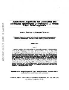
SIMULATOR DESCRIPTION In order to fulfill the CLEON tool objectives, a hybrid (continuous-discrete) multi-rate SW simulator was implemented in Matlab/Simulink. The top-level architecture is depicted in Figure 1. Two different models of optical sensors are available, global-performances models are implemented for fast Monte Carlo analysis (CLEON basic), while complex physical models are included for high-fidelity simulation (CLEON+). The blocks in orange background indicate components requiring real databases in CLEON+. Most of the models are stored in a library allowing for fast changes in the simulator, for instance addition of redundant sensors or substituting a existing component by a new one. The initial asteroid state is taken from JPL405 ephemerides and the trajectories of asteroid and SC are integrated independently in Sun-centered coordinates. The acceleration acting on the SC, apart from Sun gravitation and divert thrust, includes ACS thrust, solar radiation pressure and asteroid gravity.
2
DRIVER
NAVIGATION CAMERA OPTICAL PREPROCESS
NAVIGATION FILTER
GUIDANCE LAWS
CONTROL LAWS
STAR TRACKERS ACCELERO METER
RCS
EPHEMERIS
FORCES
SKY MODEL
TARGET
NAV SENSORS
GUI
SHAPE
ROTATION
SUN GRAVITATION TRAJECTORY INTEGRATION OTHER FORCES
TARGET IMAGE ATTITUDE SIMULATOR
GNC SIMULATOR POST PROCESS
Figure 1. Simulator main components (top level architecture)
From the Graphical User Interface (GUI) the user can edit all the configuration files and perform some simple mission analysis to help in the selection of scenario parameters. In addition, the GUI allows the user to select different sensors and actuator configuration, covering different SC architectures, for instance, • • • • •
Separate sensors for asteroid observation (navigation camera) and attitude determination (startracker), or a unique sensor for both relative navigation and attitude estimation Mount the sensors in the same baseplate or in separate plates (thermoelastic effects included) Different number and configuration of thrusters Impulsive (pulse-modulated) or continuous (electric) propulsion Attitude control system (ACS) guidance either inertial 3-axis stabilized or target-pointing (maximizing power generation)
The difference between CLEON and CLEON+ consists in the level of detail of the optical sensors models. The different level of physical modeling results in different computational time, e.g. in CLEON one Monte Carlo shot takes ~15 s (compiled simulator) or ~20 min for not-compiled simulation, whereas CLEON+ not-compiled simulation runs slightly faster than real-time. The GUI allows selecting the type of simulation, Monte Carlo with autocoding capability or opening the simulator and running manually one simulation (the option for making changes in the simulator if needed). CLEON includes the following models within the optical sensors (navigation camera and star-tracker) for global performances simulation of attitude and LOS. • • •
•
The target magnitude has a configurable Exponentially Correlated Random Variable (ECRV) added to the ideal magnitude The center of brightness (CoB) motion around the center of mass (CoM) can be simulated as, (1) harmonic, (2) an ECRV, or (3) harmonic motion plus ECRV The LOS and attitude performances are computed including the following errors o Noise Equivalent Angle (NEA) that is function of the real image (exposure time, visual magnitude of target and stars in the field of view (FOV), sky magnitude), optics (transmittance, point spread function (PSF), stray light), detector assumed to be a CCD (pixel size, quantum efficiency, fill ratio), and electronics (read-out noise, dark current) o Centroid error and other miscellaneous sources of Gaussian error o Mounting bias and (thermal) drift o The navigation camera includes an extended-target error model The image processing computes a stacking of the navigation camera observation in order to increase the signal-to-noise ratio of the measurement entering the navigation filter.
3
CLEON+ simulator includes enhanced models of the optical sensors for creating high fidelity images and for processing them subsequently. The models involved in the process are briefly explained below. •
•
•
•
•
• •
The Tycho-2 star catalogue (containing 2.5 million stars up to magnitude 12) is processed to compute the stars in the FOV of navigation camera and star-tracker, adding the orbit aberration to the stars inertial direction Advanced star-tracker model including, o Preprocessing of the visible stars to select the most appropriate for attitude estimation o Addition of errors to the stars direction depending on the pixel location, spatial error due to detector irregularities, and a NEA error, white Gaussian noise depending on the star and sky magnitude, including stray light from target, stars and sky o SC attitude estimation using the q-method 5 The still image of target is generated assuming Lambertian body lit from a point source, where the shape, rotation and albedo are defined by the user, and computed with realistic illumination conditions (surface lighting and radiance, auto-shading, camera position, orientation and FOV) The perfect still image taken by the navigation camera (Figure 2) results from the composition of the target image and the stars background, considering the stars occultation by the target, and assuming a focused navigation camera with narrow FOV and mounting a CCD The lens distortion is added by means of an expansion typical of good-quality optics that includes terms for offset, skew, scaling factor, radial distortion up to 4th order, horizontal and vertical curvature, and vertical enlargement The camera motion effects are included, mainly translation and rotation and linear motion blur due to finite image integration time (photons coming from a point source are smeared) The detector and electronics effects are included: stray-light, quantum efficiency, fill factor, nonisotropic gain, dark current, read-out, quantization, saturation, miscellaneous white Gaussian noise
Figure 2. Example of perfect still image (normalized for showing the stars background)
The image processing (IP) algorithm extracts the LOS information from the images affected by real camera effects. Initially, the NEO is so faint that the detected photoelectrons from the target are small compared with the image bias or noise. In order to increase the signal-to-noise ratio of the electron count coming from the target, a stacking of images is carried out prior to the computation of the LOS to the CoB. The sequence of operations of the IP algorithm is the following, •
•
Camera calibration to remove the bias from raw images subtracting a master dark frame. The master dark frame is computed averaging a configurable number of raw images taken with the same exposure time and temperature of the detector and electronics than in the navigation images Stacking of calibrated images to make the target detectable against a darker grainy background (Figure 3). The calibrated images are co-aligned prior to the addition. The effect of the image
4
•
stacking is equivalent to a longer exposition time, but the stacking relaxes the constraints on the ACS and prevents saturation and blooming Centroiding of the pixel counts in a search-box to find the direction to the CoB. Prior to the centroiding, a configurable threshold filters the faintest pixels and the isolated bright spots are rejected (if flag configured by user)
Figure 3. Left: normalized image result of stacking 128 raw images at beginning of the terminal phase of 2002 AT4 scenario. Right: normalized image of the search box before thresholding
GNC ALGORITHMS There are several implemented navigation algorithms to estimate different parameters, but all process the same inputs coming from the optical sensors, a star tracker and a navigation camera, independently of their configuration. The available navigation algorithms are the following, • •
For LOS navigation, i.e. to provide a smoothed LOS and LOS rate, a digital fading-memory filter 6 or a batch-sequential least-squares filter. For state navigation, i.e. to estimate the impactor state relative to the target, a sequential KalmanSchmidt filter 7.
The fading memory is a digital second order filter, i.e. assumes a linear trend in the input variable (the LOS). The filter is formulated in Eq. 1, where yk is the filter output at time tk, xk is the input, and ρk is the a-priori residual (difference between the input and the predicted output). This filter requires only one configuration parameter, the LOS-rate gain G2.
(
)
y k +1 = y k + (t k +1 − t k ) y& k + 1 − (1 − G 2 ) 2 ρ k +1 y& k +1 = y& k + [G 2 /(t k +1 − t k )] ρ k +1 ρ k +1 = x k +1 − [y k + (t k +1 − t k ) y& k ]
Eq. 1
The least-square batch-sequential filter assumes also a linear model for LOS fitting and implements a Square-Root Information Filter (SRIF) 8 for batch least-squares update formulated in Eq. 2, where Xk is the parameter matrix at epoch tk, Pk the covariance matrix, yk the observation vector, T() represents the Householder reflection 9, hk is the observation matrix, and ρk the vector of measurements residuals. The filter is sequential because an update is made with every new measurement. The configuration parameters are the length of the batch and the number of batches of the moving window.
5
S k− T( h k
Z k− S k+ Z k+ ) = y k 0 ρk (S k− ) T S k− = Pk− − k
− k
Z =S X
Eq. 2
− k
For full translational state estimation a Kalman-Schmidt filter 7 is implemented, the measurement update is formulated in Eq. 3, where xj is the augmented state vector (includes a LOS bias) at time tj, Pj is the state covariance matrix, δyj is the difference between real and estimated measurement, Hj is the observation matrix, and Rj is the covariance matrix of the zero-mean, time-uncorrelated, additive measurement noise. The propagation considers the 3rd-body gravity gradient and the maneuvers uncertainty in the covariance. The update with every new measurement is recursive to smooth the nonlinearities, and the bias state and covariance are reset after. Due to the non-observability of the full state during most of the terminal phase, the covariance matrix becomes ill conditioned but the numerical implementation assures its positive definiteness. The configuration parameters are the initial covariance, the model noise and the measurement uncertainty.
x +j = x −j + K j δ y j + T T − P j = (I − K j H j ) P j (I − K j H j ) + K j R j K j
[
K j = P j− H Tj R j + H j P j− H Tj
Eq. 3
]
−1
The suite of autonomous guidance schemes that compute the divert maneuvers includes, •
•
Predictive-impulsive 2, 4, which computes an impulsive maneuver at a predefined time that ideally cancels the Zero-Effort Miss (ZEM) with respect to the center of brightness (CoB). The gravity gradient of the 3rd-body is considered in the delta-V computation. The configuration parameters are the times of execution of the maneuvers. Proportional-navigation 6, 10, which computes an acceleration vector proportional to the LOS-rate and the homing velocity vc (Eq. 4) that reduces the line of sight (LOS) rate. The only configuration parameter is the navigation ratio N.
r d LOS a divert = NvC dt •
Eq. 4
Hybrid scheme, which implements mid-course predictive-impulsive guidance and terminal proportional-navigation. The configuration parameters are the execution times of the impulsive maneuvers, the start time of the proportional navigation and the navigation ratio.
The control algorithm transforms the computed inertial acceleration into burning time of each thruster, considering the number and orientation of the thrusters. In the predictive guidance (impulsive maneuvers), the thrusters take some cycles to complete the commanded delta-V and the control computes the average acceleration in the next cycle using the accelerometer information. The saturation is not considered in the control algorithm but in the RCS model.
RESULTS WITH CLEON BASIC VERSION Two different NEO are selected as representative targets for performance evaluation of benchmark scenarios. Asteroid (10302) 1989 ML is considered as a slow-rotating target with ellipsoidal shape of moderate ellipticity, while asteroid 2002 AT4 is taken as a fast rotating target with very irregular shape. The main target characteristics affecting the GNC performances are presented in Table 1. The last 3 rows are only applicable to the CLEON basic version, since the CoB motion results naturally from the target shape and illumination and observation conditions in CLEON+. In the case of 2002 AT4, the time constant of the CoB ECRV has been selected much shorter than the rotation semi-period to emphasize irregular shape effects.
6
Table 1. Target characteristics Parameter Absolute magnitude Slope parameter Gravitational constant (m3/s2) Diameter (m) Rotation period (hour) Orbital period (year)
1989 ML 19.35 0.15 15.35 600 19 1.436
2002 AT4 20.96 0.15 15.35 265 2.2 2.549
CoB type of motion CoB motion amplitude (m) CoB ECRV time constant (s)
ECRV+harmonic 50 34200
ECRV 48 630
One of the key components of the autonomous impactor is the navigation camera. The design objective is to have a small camera (size and weight), not too technology demanding (low-cost). With this purpose the parameters of the camera were selected, and are presented in Table 2 along with the values of other navigation cameras used in past missions (SMART-1 AMIE camera was not specifically designed for navigation). Table 2. Navigation camera characteristics Parameter Aperture diameter (cm) FOV Pixels in CCD Read-out noise per pixel Quantum efficiency Exposure time (s)
CLEON 2.5 (1989 ML) 5.0 (2002 AT4) 3º 1024x1024 30 e− 30% 0.08 (1989 ML) 0.125 (2002 AT4)
AMIE (SMART-1)
ROSETTA
Deep Impact
1.6
7
12
2.15º 512x512 30 e− 18%
2.5º 1024x1024 15 e− 33%
0.573º 1024x1024
-
-
0.2 - 10
-
The navigation camera parameters together with the impact conditions set the image processing detectability constraint. Given the visibility requirement (a day before impact), the approach velocity (10 km/s) and the NEO position at impact (perihelion at ~1.1 AU), the initial apparent magnitude can be computed as function of phase. For 1989 ML and 90º-impact, the magnitude is 11.5, while for 2002 AT4 and 70º-phase, the magnitude is 12.4 (above the 12 limit of the Tycho-2 star catalogue). From these initial conditions, the image stacking and GNC parameters are initially configured and Monte Carlo simulations are run. The initial state dispersion is assumed isotropic and includes interplanetary orbit determination and target ephemeris uncertainty, for both scenarios the position dispersion is 250 km and the velocity dispersion is 1 m/s. The summary of the Monte Carlo results (64 runs each) is presented in Table 3. In the 1989 ML scenario all the proposed navigation algorithms and guidance strategies are nearly equally well suited, i.e. all impacts well within the target shape (maximum miss distance much smaller than target radius) and delta-V assumable by a small SC. The main remark is that the tuning of the hybrid guidance makes that the delivery accuracy is improved, in comparison with the other algorithms, at the expense of an increase in the delta-V budget. Figure 4 to Figure 7 depicts some representative information related to the performance of each GNC in this scenario. The 2002 AT4 scenario is more demanding because of the large amplitude of the CoB motion (48 m) compared with the target shape, and the very short time constant of this movement (630 s). This configuration is not very realistic because the CoB will move with a period roughly half of the asteroid rotation period and will not suffer such strong variations as an ECRV (furthermore only in very rare configurations the CoB can be outside the shape). However, it was selected to stress to the limits the GNC algorithms and show the mission characteristics driving the GNC performances.
7
Table 3. Monte Carlo analysis summary 1989 ML GNC Algorithm
2002 AT4
CEP (m)
Miss max (m)
∆V max (m/s)
CEP (m)
Miss max (m)
∆V max (m/s)
Batch-sequential + predictive (10 N)
12.3
38.5
16.1
57.9
140
19.5
Kalman + predictive (10 N)
14.6
33.6
15.7
50.1
162
19.0
Fading memory + proportional (0.15 N)
13.6
37.1
19.1
65.1
140
21
Fading memory + hybrid guidance (1 N)
9.9
29.1
50.9
57.4
152
24
The results show that the final circle of error probable (CEP) of the miss distance nearly matches the amplitude of the CoB motion, because in the very last minutes the SC cannot compensate this CoB deviation due to its fast movement. Even if at the end of the mission the observability is very good, the authority is much limited because of the reduced time to go. Even with this extreme configuration, the performances are very good (see the cumulative distribution function (CDF) of the miss distance in Figure 8 and Figure 9) and few runs do not impact the asteroid, although in CLEON basic version the shape is not included and therefore this analysis is not possible. All these effects are appreciated in the results shown from Figure 8 to Figure 11, note that the effect of the 3rd-body in the impact vector is much higher in the 2002 AT4 than in the 1989 ML because in the later, the approximation is at 90º-phase and the linear term of the 3rd-body is null.
Figure 4. 1989 ML scenario Monte Carlo results for batch-sequential least-squares filter and predictive guidance (10 N). Left: CDF of miss distance. Right: impact point distribution in B-plane.
Figure 5. 1989 ML scenario Monte Carlo results for Kalman-Schmidt filter and predictive impulsive guidance (10 N). Left: impact parameter evolution. Right: CDF of delta-V.
8
Figure 6. 1989 ML scenario Monte Carlo results for fading memory filter and proportionalnavigation (0.15 N). Left: impact parameter evolution. Right: evolution of impact vector (B-plane).
Figure 7. 1989 ML scenario Monte Carlo results for fading memory filter and hybrid guidance (0.15 N). Left: impact parameter evolution. Right: evolution of impact vector (B-plane).
Figure 8. 2002 AT4 scenario Monte Carlo results for batch-sequential least-squares filter and predictive guidance (10 N). Left: CDF of miss distance. Right: impact point distribution in B-plane.
9
Figure 9. 2002 AT4 scenario Monte Carlo results for Kalman-Schmidt filter and predictive impulsive guidance (10 N). Left: impact parameter evolution. Right: CDF of miss distance.
Figure 10. 2002 AT4 scenario Monte Carlo results for fading memory filter and proportionalnavigation (0.15 N). Left: impact parameter evolution. Right: evolution of impact vector (B-plane).
Figure 11. 2002 AT4 scenario Monte Carlo results for fading memory filter and hybrid guidance (0.15 N). Left: impact parameter evolution. Right: evolution of impact vector (B-plane).
10
RESULTS WITH CLEON+ (HIGH-FIDELITY OPTICAL SENSORS) The CLEON+ version did not allow for Monte Carlo simulation because of the image generation high computational load. Nevertheless, the single run simulation with high-fidelity optical sensors models allows for the confirmation of sensors and GNC configuration in the CLEON basic version scenarios and for validating the obtained performances. The shape models used for the generation of the target perfect image are depicted in Figure 12, where the strong impact of the auto-shading in the magnitude and CoB location of 2002 AT4 (with the 433 Eros shape) can be seen, in approximately 1000 s the magnitude increases more than 2.5 magnitudes (from ‘full disk’ to hardly visible). The target rotation vector is selected normal to the initial LOS and along the axis of highest inertia moment, in order to have the maximum CoB variation in the detector plane and maximum peak-to-peak difference in brightness curve. Note that in this case, the artificial very high frequency motion is forced imposing a shorter rotation period as is seen in the abscissa of Figure 12. Only single-run simulation for one GNC algorithm per scenario is presented, the results are summarized in Table 4 along with the corresponding Monte Carlo case. The final performances of the single-run simulations are in good agreement with the Monte Carlo statistics, partly confirming the assumptions in CLEON basic version. The evolution of some interesting parameters during the simulation is depicted in Figure 13 and Figure 14. However, a more refined analysis shows that in the 2002 AT4 scenario some cases may not impact the target, as was explained in the previous section. In Figure 15 the last image immediately before the impact is shown for these scenarios where the risk of missing the target in the 2002 AT4 case is evident.
Table 4. Comparison of CLEON+ results against Monte Carlo simulations Parameter
Miss distance (m) ∆V (m/s)
1989 ML fading memory filter + proportional navigation (0.15 N) Single-run 10.347 16.42
Monte Carlo 13.6 (CEP) 19.1 (max) 10.1 (median)
11
2002 AT4 batch-sequential filter + predictive guidance (10 N) Single-run 57.989 13.40
Monte Carlo 57.9 (CEP) 19.5 (max) 9.1 (median)
Figure 12: Upper row: perfect still image of target using shape models of 433 Eros (left) and Phobos (right) for 2004 AT4 and 1989 ML respectively. Lower row: instrument magnitude during one revolution with the rest of the geometry frozen
Figure 13. 1989 ML scenario single-run results for fading memory filter and proportionalnavigation guidance (0.15 N). Left: impact parameter evolution. Right: evolution of target integrated magnitude.
12
Figure 14. 2002 AT4 scenario single-run results for batch-sequential least-squares filter and predictive guidance (10 N). Left: impact parameter evolution. Right: evolution of target integrated magnitude.
Figure 15. Normalized frame 1 s before impact showing the navigation solution (LOS & LOS-rate), the impact point and the CoM for single-run simulations. Left: 1989 ML scenario with fading memory filter and proportional-navigation guidance (0.15 N). Right: 2002 AT4 scenario with batch-sequential least-squares filter and predictive guidance (10 N). The frames are shown during simulation for monitoring the evolution of the performances and are stored as an animation file
13
CONCLUSIONS A hybrid (continuous-discrete) multi-rate simulator for the terminal phase of a hypervelocity NEO impactor was developed for the design of autonomous GNC prototypes, and to help in the process of mission requirements definition and SC system design. Two levels of optical sensors modeling allows for, • •
Fast Monte Carlo analysis of benchmark scenarios (~15 s per shot) with global performances modeling of optical sensors and IP, or Validation of Monte Carlo analysis and highlighting IP effects with the high-fidelity optical sensors models and IP prototype.
The simulator has several SC configurations available allowing for fast sizing of the sensor suite and propulsion system, and for a quick assessment of mission and system requirements. The implementation has considered the flexibility to adapt to different SC configurations and to new types of missions. The Monte Carlo analysis of benchmark scenarios show promising results for small, low-cost impactor targeting small, faint NEOs. All implemented GNC strategies show similar good performances and are potentially applicable; therefore, trade-off solution needs additional mission- or system-specific requirements. For the 1989 ML slow, ellipsoidal asteroid, very good performances (delivery accuracy and delta-V budget) are achieved. For the 2002 AT4 asteroid, an artificial very high-frequency, highamplitude CoB motion is imposed and the statistics indicate the lack of authority to follow precisely this fast movement, but the miss distance is still acceptable for most of the cases. The results of single-run, high-fidelity simulations for some of the benchmark scenarios show good agreement with Monte Carlo statistics, partially confirming the assumptions in the global performances modeling of optical sensors. The IP effects are more evident in this case showing some of the foreseen problems in the Monte Carlo analysis of 2002 AT4 with the artificial fast rotation. The good results of these high-fidelity simulations reinforce the feasibility of low-cost, autonomous impactor missions to small NEO.
REFERENCES 1.
A.W Harris et al. “Mitigation-relevant science with Don Quijote - a European-led mission to a nearEarth asteroid”, 36th COSPAR Scientific Assembly, 16-23 July 2006, Beijing, China 2. D. Kubitschek. “Impactor Spacecraft Targeting for the Deep Impact Mission to Comet Temple 1”, AAS 03-615 3. W. M. Owen et al. “Optical Navigation for Deep Impact”, AAS 06-176 4. T. Bank et al. “Deep Impact: 19 Gigajoules Can Make Quite an Impression”, 24th AAS Guidance and Control Conference, 2001, AAS 01-022 5. J. Wertz. “Spacecraft Attitude Determination and Control”, Kluwer Academic Publishers 6. P. Zarchan. “Tactical and Strategic Missile Guidance, 2nd Edition”, Progress in Aeronautics and Astronautics, Vol. 157 7. S. F. Schmidt. “Estimation of State with Acceptable Accuracy Constraints”, NASA-CR-84795 8. G. J. Bierman. “Factorization Methods for Discrete Sequential Estimation” ”, Academic Press, New. York, 1977 9. G. H. Golub, C. F. van Loan. “Matrix Computations, Third Edition”, Johns Hopkins University Press, Baltimore, 1996 10. G. M. Siouris. “Missile Guidance and Control Systems”, Springer-Verlag, New York, NY, 2004
14