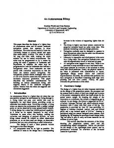
Autonomous Monitoring and Control (ASMAC) - An AUV Fleet Controller Sai S. Mupparapu, Steven G. Chappell, Rick J. Komerska, D. Richard Blidberg Autonomous Undersea Systems Institute, Lee, NH {sai, chappell, komerska, blidberg}@ausi.org
Robert Nitzel, Charles Benton Technology Systems Inc., Wiscasset, ME {rnitzel, cbenton}@technologysystemsinc.com
Dan O. Popa, Arthur C. Sanderson Rensselaer Polytechnic Institute, Troy, NY
[email protected] [email protected]
Abstract – Monitoring and controlling multiple Autonomous Underwater Vehicles (AUVs) can quickly become cumbersome, especially when dealing with missions extending over multiple days and when dealing with heterogeneous vehicles. The goal of ASMAC is to simplify this process so that it is easier for a user to monitor and control heterogeneous vehicles. ASMAC will achieve this through the use of a Common Control Language (CCL) that provides a common interface to heterogeneous systems and interactive planning models to help the user in the mission planning phase. ASMAC will also interface to the Cooperative AUV Development Concept (CADCON) simulation environment to help the user verify mission plans. 1.0 INTRODUCTION
Autonomous Systems Monitoring and Control (ASMAC) is a software application under development that will allow a user to control multiple AUVs. ASMAC will allow a user to plan a mission, configure a fleet of AUVs that are going to accomplish that mission, initiate the mission, monitor the mission while it is underway, analyze received mission data and vehicle status and, as a result of that analysis, modify the mission while it is underway. ASMAC is being designed to guide a user through a process that configures a fleet of AUVs to accomplish a desired mission. This process will require the user to identify parameters that describe: • the Mission Description • the Strategies to be used for Cooperation • the Conventions/Behaviors to be used to accomplish the mission • the Information and Data Required to implement those behaviors • the Communications Required to implement those behaviors • the Vocabulary Required Once the mission has been defined and the mission systems configured, the mission can be executed. ASMAC
0-7803-8543-8/04/$20.00 © 2004 IEEE.
will then allow monitoring of the mission to evaluate the system’s performance. Changes to the defined mission can then be made to insure mission completion. To accomplish these tasks, ASMAC must be able to accomplish the following requirements: • Provide tools to plan a defined mission : - display and allow configuration of CCL statements and the parameters associated with them - provide a method of grouping together CCL statements to form aggregate behaviors - describe existing conventions - develop new conventions - plan movement, mission activities, communications, action/emergency scripts • Provide an interface that allows a mission to be simulated/monitored : - understand impacts of individual action on total system capability, energy (individual and total system), collisions, communications, sensing, and other resources - verify that the defined mission can be accomplished • Provide a means to compile and communicate mission commands : - ability to communicate commands to individual vehicle systems - ability to verify reception of commands - ability to begin the mission execution • Provide an environment to monitor the mission while it is being accomplished : - allow status and sensed data to be verified, logged and displayed - display progress of the actual mission relative to the planned mission - provide mission analysis tools to recognize and analyze possible faults - determine an updated understanding of environmental parameters such as currents (tidal, surface, and subsurface) and bathymetry
• Provide an environment to allow re-planning while the mission is underway : - provide tools to allow analysis of status and sensed mission data - allow modifications to be communicated to individual vehicles This paper contains eight sections. Section two gives a background on the various Autonomous Undersea Systems Institute (AUSI) projects that will impact or benefit from an ASMAC effort. Section three talks about the motivation for this project and the approach adopted. Section four briefly describes the CADCON simulator. Section five gives a detailed description of ASMAC. Section six describes the interface between ASMAC and an Adaptive Sampling Algorithm (ASA). Section seven presents some results from our recent testing event using ASMAC, and the paper concludes in section eight. 2.0
BACKGROUND
AUSI is actively involved in researching five different areas relating to multiple AUVs: a long endurance vehicle, communications, a common control language, adaptive sampling strategies, and a mission-programming environment to control a fleet of AUVs. All five projects come together under one umbrella program called Multiple Cooperative Autonomous Underwater Vehicles (MCAUV). The MCAUV program is funded by the Office of Naval Research (ONR) under grant #N00014-04-1-0264. These projects are described briefly in the remainder of this section. Solar Powered AUV (SAUV): AUSI is currently developing a solar-powered autonomous underwater vehicle [1] in partnership with Falmouth Scientific, Inc. (FSI) of Cataumet, MA and Technology Systems, Inc. (TSI) of Wiscasset, ME. Figure 1 shows the system and components of the SAUV. The goal of this program is to develop an AUV system capable of autonomous underwater sampling with long endurance. In-water testing has been conducted off Cape Cod, MA, and recently on Lake George at Bolton Landing, NY. This program is funded by ONR under contract #N00014-03-C-0109. Autonomous Undersea Systems Network (AUSNET): AUSNET is a National Science Foundation (NSF) funded STTR Phase 2B program (Grant #DMI-032084) and ONR funded (Contract #N00014-04-C-0094) addressing network protocols for underwater communications. This joint effort is being performed by TSI and AUSI. The goal of AUSNET is to enable expanded networking services specially tailored to the acoustic environment and AUV operational scenarios. This effort builds upon emerging ad-hoc (self-forming, selfmaintaining) network protocols. This project is further discussed in a parallel paper entitled “Autonomous Systems Network.” [2] RiverNet - Distributed Sensor Nets for Environmental Monitoring: AUSI recently received a subcontract award from Rensselaer Polytechnic Institute (RPI) to use the SAUV platform in conjunction with a fixed mooring to sample
Figure 1: SAUV System Components
pollutants in the Hudson River. This program addresses a number of issues associated with adaptive sampling using autonomous systems. This project is funded by the National Science Foundation (Grant #IIS-0329837). This project is further discussed in a parallel paper entitled “Adaptive Sampling Algorithms for Multiple Autonomous Underwater Vehicles.”[3] Autonomous Systems Monitoring and Control (ASMAC): AUSI is also working on the development of Autonomous Systems Monitoring and Control (ASMAC). This effort focuses on investigating the issues associated with a mission-programming environment required to control multiple AUVs. Common Control Language (CCL): AUSI, in cooperation with the Naval Undersea Warfare Center (NUWC), is working on identifying a Common Control Language (CCL) [4] that can be used by heterogeneous AUVs for communication of commands and information. This project is funded by the Office of Naval Research under Grant #N00014-02-1-0081. The project is further discussed in a parallel paper entitled “Talk Amongst Yourself: Getting UUVs to Cooperate.”[5] 3.0 MOTIVATION AND
APPROACH
While planning a multi-AUV mission, the user needs to consider effects of parameters such as energy resource, communications, and environmental conditions. Every kind of vehicle will have its own capabilities and constraints. Hence monitoring and controlling multiple AUVs can easily become cumbersome, especially when dealing with missions extending over long duration and when dealing with heterogeneous vehicles. The goal of ASMAC is to simplify this process so that it is easier for a user to monitor and control heterogeneous vehicles. ASMAC will achieve this with the help of a CCL that provides a common interface to heterogeneous systems and interactive planning models to help the user in the mission planning phase. ASMAC will also interface to the CADCON simulator in order to test the created mission, giving the user a better insight of the mission. In developing ASMAC, we have adopted the approach of user-centric & empirically-based design. A key goal is to
make the program usable to a range of users. An ocean scientist, for example, may prefer to treat a fleet of AUVs as “black boxes” having capabilities that he or she can utilize to carry out their particular mission. To develop such a program will require an iterative design and development process. This will be achieved in part by performing a series of inwater tests while closely interacting with various users. The feedback from this interaction will be incorporated as appropriate.
•
3-D View of Environment & Vehicle Interaction Visualization Client
AUV Simulation Client
• Simulate AUV • Evaluate multi-AUV
Internet
Autonomous Systems Monitoring & Control Client
Behaviors
4.0 CADCON
As an aid to our investigations in the area of multiple cooperating vehicles, AUSI has developed the Cooperative AUV Development Concept (CADCON) [6]. This facility employs a distributed multi-agent simulation, visualization system, and control harness designed to simulate a fairly accurate underwater environment. This environment can be shared by simulated or real vehicles connected via the Internet. To date, this facility has been used to support several AUSI projects. The facility is available via the Internet for others to use and it has been employed by independent workers in industry and academia to support their own research projects. The main idea behind CADCON and its simulator is that it provides an open and flexible environment for use by as many researchers as possible. Understanding that no single simulation harness could capture the full fidelity of real open water environments, or the complexity of every sort of vehicle that might participate, we have focused our efforts on designing CADCON to address one important aspect of multiple vehicle systems. That is, dealing with those issues associated with the higher level interactions among multiple heterogeneous participants; be those participants real vehicles, simulations of vehicles, or even human users. This broad participant heterogeneity pushes us to refer to them as agents. To enable this, we have endeavored to streamline the complexity and the costs associated with an agent's connection to the CADCON simulator. In particular, we have implemented the system's various components on ubiquitous hardware. These components embody the client/server model and communicate via a simple connection protocol which rides on TCP/IP. This non-reliance on exotic hardware and/or proprietary communications protocols allows other researchers to leverage the simulator's utility for their own work. Figure 2 shows the architecture and the different components of the simulator. In brief, the Environment Server provides a cuboid water body having several properties such as temperature, water currents, chemical plumes, etc. The AUVSim client simulates an AUV that swims in the water body. The Visualizer client enables a user to view the environment and vehicle interactions. Finally, a simplistic ASMACSim client allows a user to monitor and control the AUV simulation clients in a manner similar to how the actual ASMAC application will interact with inwater vehicles; namely, through a common control language.
Environment Server
• Scenarios • Environments • Sensor & Communication
Models
Figure 2: Architecture and components of CADCON 5.0 ASMAC
ASMAC is the interface between the user and the system of multiple AUVs. It communicates with the vehicles using a Common Control Language. It will also be the communications interface that allows the user to communicate with any and all of the vehicles involved in accomplishing the defined mission. Currently it is proposed that ASMAC will provide the following capabilities. These capabilities will allow a user to follow the process as diagramed in Figure 3. The mission will be described by developed CCL scripts for each vehicle. ASMAC will, upon command, download those mission scripts to the individual vehicles. The vehicles then begin the mission upon receiving an execute command. While operating, the vehicles return status data to ASMAC, which is plotted or otherwise displayed for the user. The user can then modify the plan based on the status data or acquired scientific data and download the new mission scripts to the vehicles. The vehicles then execute the modified mission plan. In the configure stage, ASMAC will present an environment that will allow a user to describe the mission, environmental parameters (such as currents and bathymetry) and vehicle systems capabilities, and resources (e.g. energy usage, communications). A user with limited knowledge of the system can easily be overwhelmed by the different configuration parameters. To address this situation, ASMAC will be equipped with a “wizard” that will walk the user through the configuration stage. In the planning stage, the user will be able to accomplish mission identification and system identification, configure CCL parameters, group CCL commands to form aggregate behaviors, describe existing conventions or develop new conventions, plan movement, mission activities, communications, and emergency scripts. ASMAC will provide a 2D plan view, text entry options and static and non static data and information display. The planning stage will be equipped with interactive planning models that provide interactive help to the user while planning a mission. Section 5.2 discusses planning models in more detail.
• Web based: ASMAC creates data packages and ships the appropriate data/information to a specific active web site, designed to display that data. Anyone with WWW access would then access that site using a standard browser. If necessary, the site could be equipped with passwords in order to restrict public access to selected ASMAC activity. The web site could be simple (showing in text what is going on) or complex (using VRML to display in 3D what is happening). • ASMAC Client: This implementation involves designing ASMAC with server-client architecture. The ASMAC server would specialize in communicating with the vehicle fleet. The client(s) would specialize in receiving and displaying the data/information. • CADCON Client: This implementation would leverage the AUSI CADCON Environment Server's existing ability to make multiple vehicle data available to remote viewers. Figure 3: Sequence of user stages in ASMAC
5.2 Planning Models In the simulation stage, ASMAC will provide a 3D graphical display of the AUVs executing the proposed mission. A user will be able to understand the impacts of individual action on total system capability such as energy (individual and total system), collisions, communications, sensing, and other resources. A user can iteratively plan and simulate until he or she determines that the defined mission can be accomplished. Implementation of the simulation can be done in two ways. First, a non-real time simulation could be implemented in ASMAC that directly utilizes the planning models. Second, an interface to CADCON can be developed to achieve a real-time simulation. To enable this capability, enhancements have to be made to the existing CADCON system. In the execute stage, ASMAC will have the ability to communicate commands to individual vehicles (directly, via store and forward, and via a group leader), the ability to verify reception of commands, and the ability to begin the mission execution. Once the mission execution is underway, the user can monitor its progress. During all of these stages, ASMAC will allow the user to monitor status and sensed data. This provides the capability for this information to be verified and logged, as well as display of the progress of the actual mission relative to the planned mission. It will provide mission analysis tools to recognize and analyze possible faults, and determine and update understanding of environmental parameters such as currents (tidal, surface, subsurface) and bathymetry.
During the planning stage, the user will need to consider many parameters in order to plan a robust mission. The intent of the planning models is to aid the user in this process by providing estimated information. For example, consider the energy resource. Simple information such as how long will the energy resource last (estimate) and how much energy will be remaining at the end of the mission will help the user better plan the mission. Figure 4 shows some ideas on how this information might be displayed. ASMAC will have the ability to signal the user with warnings/alerts if any model produces results which cross user-configured thresholds. One way to present this information is by displaying a gas gauge alongside the vehicle icon, also show comparison gauges together, as well as a total end-of-mission energy gauge. ASMAC could show a yellow (warning: low battery) and a red (danger: very low battery) overlay on the appropriate track lines. -1 -2 UV UV SA SA
Battery Charge % 28 64
5.1 Providing Access to ASMAC for Remote Observer When a user is engaged in controlling a fleet of vehicles with ASMAC, we believe it is important to make that activity viewable by other groups at different locations. One objective of the MCAUV program is to implement this capability. To accomplish this, we are exploring the following implementation options:
Figure 4: Energy Resource Planning Model Display
Another example would be inter-AUV and ASMAC communications availability. ASMAC could show overlaps
on planned track lines where communications are possible, as well as time windows where communications are possible with ASMAC. Also, communications radii around each vehicle icon might be diagrammed. ASMAC could leverage AUSNET algorithms for estimating AUV communications connectivity. Figure 5 shows this concept.
07:15
09:48
Figure 5: Communications Planning Model Display
Similarly, the following models are currently being researched: • Solar insolation model: Show periods of nighttime overlay with track line. Could also show relative cloud cover in similar fashion, with average daily insolation numerical values next to track line. • Bathymetry: 2D display will use C-MAP [7] view or custom plan view if appropriate. If bathymetry available, this can be used to check for minimum vehicle altitude • Currents: Shows the effect of tidal, subsurface and surface currents on vehicle waypoint acquisition ability. • AUV motion and position: checks on vehicle capabilities (min/max speed, maneuvering capability, max depth, min altitude). Prevent user from inputting these parameters during planning. Also use with currents and energy management input to indicate if waypoint acquisition will be possible. Could also show DR uncertainty. • Other environment models:. Utilize NetCDF interface for access and display of data models (e.g. DO plume) and received/stored sensor data. • User-defined restricted regions: Allow user to define spatial/temporal regions where vehicles are restricted from entering (or leaving). • Cooperative vehicle assessment model: Initially allow the user to set thresholds on vehicle and mission parameters where alerts will be generated if crossed. More advanced models will provide suggestions to the user on corrective course of action. Thresholds triggers could be based on imminent collision, change of group leadership, position in space, time, activity sequence, energy state and data sharing activity.
5.3 Components and functionality of ASMAC Figure 6 shows the proposed architecture for ASMAC. The core application that drives the ASMAC is the 2D display with parameter editing for vehicles, planning models and mission scripting. The ASMAC core provides the user interface for working with the planning models as well as the coordination (data passing) between the models. It also updates the master mission planning database (MMPD) and master mission status database (MMSD). In addition, it accesses the MMPD and MMSD for display of model output and status history, respectively. It also packages proprietary sensor and engineering data for 3rd party consumption. The MMPD is a database having 3 dimensions: time, vehicle and planning values, which spans the entire planned mission timeframe. Initially, a fixed time delta shall be imposed which comprises the minimum time granularity of the planning interface.
3D View
File Configuration Planning Transfer
Parameter Input & Controls
2D Plan View
Display Commands Interaction & Display Planning Task
ASMAC Core
Comms
AUVs
Planning Model DLL
Planning Model Database
Master Mission Planning Database
Master Mission Status Database
NetCDF File
NetCDF File
(optional) NetCDF File
Proprietary Sensor or Engineering Data 3rd Party File
x n different models
x n different data sets
Figure 6: ASMAC Architecture
The MMSD is a database having 3 dimensions: time, vehicle and mission status values, which spans the mission timeframe from mission start through the last status update. Time deltas reflect the actual updates from the AUVs. Both MMPD and MMSD will use the NetCDF file format for handling data. Planning models will utilize DLL libraries to provide standardized modular interface to planning models as well as processed sensor data and vehicle and environment configuration information.
5.4 Present version of ASMAC The current version of ASMAC (rev 0) was initially implemented by TSI. This section presents some screen shots of this application in action. ASMAC is a Windows OS application which utilizes C-MAP for 2D display of nautical charts. Figure 7 shows the 2D-monitor view of ASMAC. The tab view on the right corner presents the status information of the vehicle. The status information consists of vehicle health, location, attitude, and other critical information. This information is updated as frequently as the periodic updates from the vehicle. The vehicle itself is represented by a circle and a red arrow (denoting the heading of the vehicle). The position of this icon is also updated with the status information. Hence, a user can monitor the system in real time. Figure 8 shows the CCL statement editing window. ASMAC allows a user to create defined maneuvers with a few button clicks. It then lets you edit the lowest level of details of that maneuver, if needed. This editing causes changes in the appropriate CCL commands/statements in the background. Figure 9 shows the graphical user interface built on the traditional file transfer protocol (FTP). This window allows the user to transfer the created missions onto the vehicles. Figure 10 shows the configuration window that gives a user control to configure some system level parameters. ASMAC also lets the user change the sub-system parameters which are password protected for security.
Figure 8: ASMAC CCL editing
Figure 9: ASMAC Execution/Transfer
Figure 7: ASMAC 2D-monitoring
Figure 10: ASMAC Configure
Communicate via RF/Acoustic ASMAC Transfer missions and obtain logged data ASA
Transfer logged data and obtains modifications to the planned mission
Figure 12: ASMAC Interface to ASA 7.0 FIELD TESTING OF ASMAC
Figure 11: ASMAC Data Analysis
Figure 11 shows an example of post processing logged data in ASMAC. This particular example is of Watch Circle mission. When a SAUV is commanded to perform a Watch Circle maneuver, it transits to the center of the circle and stops. Then it sits and drifts until wind/water currents push it to cross the boundary of the circle (indicated by blue line). Once it crosses the boundary of the circle, it transits back to the center of the circle to repeat the process until a specified amount of time has elapsed, or specified absolute time stamp has passed. The heavy pink bands are the result of plotting a multitude of individual ‘X’ marks; each X being a vehicle position. The size of each X shows the error in the GPS. As seen in Figure 11, the analysis shows the change in the sum of surface currents and wind forces on the SAUV over time. This maneuver is of particular interest because while the SAUV is on the surface collecting energy it is also gathering scientific data. 6.0 ASMAC INTERFACE TO ASA
In an effort to support the RiverNet project, the SAUV platform is being used for testing and demonstration of Adaptive Sampling Algorithms (ASA) that are currently under development at RPI. In its current state, ASMAC provides the required interface to the SAUV with a user in the loop. Figure 12 shows the architecture of this process. Once a mission has been planned by the user using ASMAC, it is transferred to the SAUV and executed. After the SAUV has completed the mission, the data log generated by the SAUV is transferred from the SAUV to ASMAC. ASMAC then shares this log with the ASA. ASA uses this log to generate the recommended modifications to the original mission. These modifications are then programmed into the mission using the ASMAC application and the mission is re-run. The next step will be to automate this process and eliminate the requirement of user in the loop. In the final stage, ASA will be running on the SAUV platform and constantly adapting.
The most recent testing event was performed at Bolton Landing in Lake George, NY from June 2 – 12, 2004. The logistic support was provided by Darrin Fresh Water Institute (DFWI) of RPI. The major objectives of the test event were • Engineering tests of SAUV performance • Initial testing of an Underwater Acoustic Network (AUSNET) • Data acquisition (CTD, Dissolved Oxygen) The test event primarily consisted of three mission phases (55 hrs, 63 hrs, 72 hrs) and the SAUV demonstrated an endurance of 190 operational hours during a 240 hr test period with one battery charging period of 3 hrs. The SAUV system was usually collecting solar energy only for a few hours during the day (peak sun hours 12 pm to 3 pm) and was running missions during the rest of the day. Hence, we expect the SAUV to show longer endurance when the SAUV system is actually allowed to collect energy for longer durations during the day. The ASMAC application was successfully used to monitor and control the SAUV during this testing event. All of the missions were expressed in CCL and successfully communicated to the SAUV platform. The test experience has emphasized the requirement to display history information quickly and easily. The test experience has also revealed the lack of engineering data analysis tools in ASMAC. We are currently working on these aspects and expect them to be available in the next revision of the program. 8.0 CONCLUSION
We have found from both our previous simulation work, and more recent field trials, that interacting with a single vehicle can be cumbersome and error-prone. Working with multiple vehicles will certainly place a much higher workload on the fleet operator as well as present difficult challenges in both the display of information and in the user's interaction with the AUVs. Toward this end, we have developed a prototype ASMAC application that we currently use to monitor and control our SAUV platform. We have begun to explore new ideas on
how to better interact with multiple vehicles, particularly with respect to configuration, planning/re-planning, and simulation. In particular, we envision the use of a wizardstyle utility which guides a fleet user through the initial configuration of planning models and fleet assets. We also see a use for a layered accessibility approach to these models and assets, depending on the role of the particular user. A key element in ASMAC is mission planning, and for this task, we believe it is important to provide an API which allows for new models to be easily developed and plugged into ASMAC. Output from these models, possibly in conjunction with simulation output, will provide an acceptable level of verification prior to the mission execution. Finally, the various kinds of data and information generated by the planning models needs to be displayed along with that gathered from multiple heterogeneous in-water assets, in a manner that is easily and effectively assimilated by the fleet user. In describing the ASMAC application, we have touched upon several concurrent efforts underway in the MCAUV program. Each of these efforts brings out a level of realism, particularly with respect to energy and communications, which we believe will be critical in an application such as ASMAC. ACKNOWLEDGEMENTS We would like to thank the Darrin Fresh Water Institute group and Rensselaer Polytechnic Institute for their hospitality and support during the Lake George testing event in June 2004.
REFERENCES [1] J. Jalbert, et al., “Solar-Powered Autonomous Underwater Vehicle Development”, in Proceedings of the 13th International Symposium on Unmanned Untethered Submersible Technology (UUST03), Durham, NH, Aug. 2003. [2] C. Benton et al., “Autonomous Undersea Systems Network (AUSNet) – Protocols To Support Ad-Hoc AUV Communications” in Proceedings of IEEE/OES Autonomous Underwater Systems 2004 (AUV’04), Sebasco Estates, ME, June 2004. [3] D. O. Popa et al., “Adaptive Sampling Algorithms for Multiple Autonomous Underwater Vehicle”, in Proceedings of IEEE/OES Autonomous Underwater Systems 2004 (AUV’04), Sebasco Estates, ME, June 2004. [4] Rick J. Komerska, D. Richard Blidberg, Steven G. Chappell and Liang Peng, “Progress in the Development and Evaluation of a Standard AUV Command and Monitoring Language”, in Proceedings of the 11th International Symposium on Unmanned Untethered Submersible Technology (UUST 99), Durham, NH, Aug. 1999. [5] C. N. Duarte et al., “Talk Amongst Yourself: Getting UUVs to Cooperate”, in Proceedings of IEEE/OES Autonomous Underwater Systems 2004 (AUV’04), Sebasco Estates, ME, June 2004. [6] Steven G. Chappell and Rick J. Komerska, “An Environment for High-Level Multiple AUV Simulation and Communication” in Proceedings of Collaborating and Leveraging OuterSpace and Undersea Technologies (CLOUT), NOAA/NASA Workshop, August 2000. [7] http://www.c-map.com/