capabilities under development for a 2005 Mars sample return mission and its precursor missions. ... system capabilities for each of these rover sequences are.
AUTONOMOUS ROVER TECHNOLOGY FOR MARS SAMPLE RETURN Charles R. Weisbin, Guillermo Rodriguez, Paul S. Schenker, Hari Das, Samad A. Hayati, Eric T. Baumgartner, Mark Maimone, Issa A. Nesnas, Richard A. Volpe Jet Propulsion Laboratory, California Institute of Technology 4800 Oak Grove Drive, Pasadena, California 91109-8099 Planetary rovers enable good sample selection and retrieval for Mars sample return missions. After landing, the rovers search for the best possible scientific samples in the region around a lander, and they return these selected samples to an ascent vehicle that launches the samples into Mars orbit. To streamline the search for, the acquisition, and the retrieval of samples, rover autonomy is a critical technology. This paper summarizes a series of experimental results in the evaluation and demonstration of planetary rover autonomy, with a particular emphasis on rover system technology capabilities under development for a 2005 Mars sample return mission and its precursor missions. 1.
INTRODUCTION
An autonomous system is defined here as one that can execute multiple-command sequences robustly at the remote rover site, without direct intervention by ground controllers while the sequence is being executed. The longer and more complex the task that a given rover can reliably execute by itself, the more autonomous the rover is. Execution of complex tasks with minimal ground control is essential to maximize science return for fixed mission duration, and to compensate for the long time that it takes for commands from Earth to reach their destination on the Martian surface. Four specific autonomous rover operational tasks are described in detail: Mars Sample Return Rover Operations: Using a newly developed Field Integrated Design and Operations Rover (FIDO) rover, a complete “loop” was demonstrated of remote science panoramic imaging and target selection, autonomous navigation, in situ sample observation and analysis, and robotic sample coring and extraction functions. This work, under the leadership of P. S. Schenker and E. Baumgartner of JPL, was performed in the Mojave Desert at Silver Lake, CA, an ancient site replicating Mars-like geological features, mineralogy, and terrains. Field science operations were under direction of Mars’03/’05 Co-I Ray Arvidson (Washington Univ., St. Louis, MO) and PI Steve Squyres (Cornell Univ., Ithaca, NY), providing technology verification and Mission planning insight for the future Mars exploration. Long Range Traverse and Science Acquisition: This task, under the leadership of R. Volpe and S. Hayati of JPL, involves long distance traverse from one site to another while operating in relatively rocky terrain, under the constraint that the traverse must be executed
autonomously with a single command cycle. The sequence includes the deployment of multiple instruments at various steps in the sequence, as well as the acquisition of multiple scientific samples. The experiments investigate the limits of what a planetary rover can do by itself, using technologies in on-board sensing, sequence planning, hazard avoidance, and goal confirmation. Autonomous Small-Rock Pick-Up: This task, under the leadership of H. Das of JPL, illustrates the autonomous acquisition of small rocks, using visual and touch sensors and a rover-mounted micro-arm to achieve the rock pick-up operation. This type of autonomous operation is useful in streamlining the sequence of actions that the rover and its manipulator must take in response to detection of an interesting rock sample that needs to be picked up. Two-Vehicle Surface Rendezvous & Sample Transfer: This sequence demonstrates, in a terrestrial analog experimental scenario, a terminal guidance, approach and rendezvous task that one autonomous rover executes as it comes close to another rover; and as a sample container is transferred from one vehicle to the other. This sequence illustrates techniques in visual target acquisition, on-board sequence planning, and terminal rendezvous operations. This work was conducted under the leadership of P. S. Schenker of JPL. These four rover tasks illustrate experiments and tests with a variety of flight-like rover technology prototypes that are being developed at JPL as precursors to a sample return rover flight system. The autonomous system capabilities for each of these rover sequences are summarized in the following two tables, together with the major challenges that have been addressed in each of the sequences.
Table 1: ROVER OPERATIONS ENABLED BY ROVER AUTONOMY Rover Functions vs. Sequence Type
Long Range Traverse Sequence
Sample Return Sequence
Small Rock Pick Up Sequence
Two Vehicle Surface Rendezvous not critical; sequence starts ~1 meter away visual search & localize target rover at 1-20 m autonomous cache recognition autonomous cache localization
~100 meters per command
100 meters per command;cont
not critical; sequence starts ~1 meter away
Image acquisition & object recognition
autonomous panoramic imaging in full autonomy
autonomous panoramic imaging in full autonomy
autonomous target imaging, localization and tracking every 10 cm
Sample selection
operator designated
operator designated
Sample acquisition & transfer
5 sample acquisition maneuvers per command
scientist designated (03 athena simulations) multi-instrument science; mini-corer; autonomous operations
Relative positioning, alignment & terminal guidance
autonomous visual localization; onboard, multisensor position estimation
Navigation
see two-vehicle surface rendezvous sequence
1 command triggers autonomous vehicle driving to target, arm deployment and sample retrieval continuous visual tracking toward selected rock target
autonomous intervehicle sample transfer ; move cache from one vehicle to another visual registration and guidance (~1 cm/1 deg. error at 1 meter); relative tracking
Table 2: MAIN PROBLEMS OVERCOME IN ROVER AUTONOMY Rover Functions vs. Sequence Type
Navigation Image Acquisition & Object Recognition Sample Selection
Long Range Traverse Sequence over the horizon navigation; multisensor fusion deployment of mast camera; correlation of multiple images simple but effective operator interface
Sample Acquisition & Transfer
concatenation of multiple rover commands
Relative Positioning, Alignment & Terminal Guidance
not applicable
Sample Return Sequence
Small Rock Pick Up Sequence
Two Vehicle Surface Rendezvous
build up of navigation errors; multi-sensor fusion deployment of mast camera; correlation of multiple images communications bandwidth and operator interface core from moving base; stability & robustness
none; sequence starts at ~1m staging location getting accurate range maps & localizing rock target high-resolution camera image displays sensing ground level, rock grasp and repeatable rock pick up continuity in tracking estimate between images
none; sequence starts at ~1m staging location real-time recognition of object features localization of cache from multiple images sample cache transfer maneuver
see two vehicle surface rendezvous
consistent relative position estimates
The terrestrial analog experimental scenarios illustrate the currently demonstrated autonomous rover technology, and the challenges in development and experimentation as outlined in more detail below.
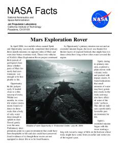
found, it may tell us if the early planet had a carbon dioxide atmosphere. The rover has shown that it can find good rocks, drill samples out of them, and take the samples back to a lander.
2. FIELD INTEGRATED OPERATIONS (FIDO) ROVER
FIDO's advanced technology includes the ability to navigate over distances on its own and avoid natural obstacles without receiving directions from a controller. The rover also uses a robot arm to manipulate science instruments and it has a new mini-corer or drill to extract and cache rock samples. There are also several camera systems onboard that allow the rover to collect science and navigation images by remote-control.
DESIGN
AND
Recently, the newest JPL rover vehicle was taken for a few practice trials around an ancient lake bed in the Mojave Desert. This next-generation Mars rover is helping NASA scientists and engineers learn more about driving the real thing on Mars. Future robotic rovers on Mars will need to find the best rocks to bring back to Earth, samples that are likely to contain the evidence scientists need to prove that life once existed on the red planet. To find the best sample, scientists need a good retriever. The FIDO -- Field Integrated Design and Operations -is helping them figure out how to use the kinds of instruments the next Mars rovers will need to fetch the most scientifically interesting rocks. FIDO [1,2] is designed to test the advanced technology of the Athena flight rover and science payload that will be launched as part of NASA's Mars Sample Return missions in 2003 and 2005. FIDO was recently tested in full-scale terrestrial field simulations of the planned Mars ’03 Sample Return mission (ref: NASA Mars Surveyor Program, Athena science rover payload). It demonstrated a complete “loop” of remote science panoramic imaging and target selection, autonomous navigation, in situ sample observation and analysis, and robotic sample coring and extraction functions. This work was performed in the Mojave Desert at Silver Lake, CA, an ancient site replicating Mars-like geological features, mineralogy, and terrain. Field science operations were under direction of Mars’03/’05 Co-I Ray Arvidson (Washington Univ., St. Louis, MO) and PI Steve Squyres (Cornell Univ., Ithaca, NY), providing technology verification and Mission planning insight for the future Mars exploration. No place on Earth is like Mars, but the field site on an ancient lake bed in the Mojave Desert comes close. The intent is to practice looking for rocks that contain carbonate minerals. If those kinds of rocks on Mars are
FIDO is about six times the size of Mars Pathfinder's Sojourner and is far more capable of performing its job without frequent human help. FIDO navigates continuously using on-board computer vision and autonomous control, and has similar capabilities for eyeto-hand coordination of its robotic science arm and mast. The rover has six wheels that are all independently steered and can drive forward or backward allowing FIDO to turn or back up with the use of its rear-mounted cameras. In addition to testing FIDO, the scientists and engineers engaged students from four schools around the country in designing and carrying out their own mission with the rover. This is the first time students have been able to remotely operate a NASA/JPL rover. The students, from Los Angeles, Phoenix, Ithaca, NY, and St, Louis, (LAPIS), formed an integrated mission team responsible for planning, conducting and archiving a two-day mission using FIDO. The FIDO rover shown in Figure 1 has a mass slightly greater than 60 kg. It has six wheels, and its dimensions are 100 cm in length, 80 cm in width, and 50 cm in height. It is a high mobility, multi-km range science vehicle, developed recently as an advance technology prototype for actual future NASA missions. It carries a mast-mounted multi-spectral stereo panoramic camera, a bore-sighted IR point spectrometer, a robot arm with an attached microcamera and a Moessbauer Spectrometer, as well as a body-mounted rock sampling mini-corer.
long-range navigation. The vehicle also carries a mastmounted point spectrometer operating at 1.25 - 2.50 microns. An arm-mounted color imager, and Raman and Mossbauer spectrometers are also part of the onboard instrumentation. A body-mounted mini-corer is used for sampling and a caching subsystem retrieves and stores samples. A belly camera is used for observation Notable outcomes of the just-completed FIDO rover Desert included multiple autonomous traverse maneuvers to science targets, using new hazard detection and avoidance software over a distance of about 100 meters under continuous traverse. Increased dead-reckoning was achieved with new wheel-velocity synchronization techniques. A “Presidential” multi-spectral panorama was constructed from approximately 1800 single images from a Panoramic Camera, totaling over 400MB in data return. Over 600 Navigation Camera images and measurements were taken with the near-IR point spectrometer. The Moessbauer spectrometer was utilized during overnight operations to analyze the field rock samples.
Figure 1: FIDO rover The FIDO Mobility Sub-System consists of a 6-wheel rocker-bogie chassis. Each wheel is independently driven and steered with a 35 N-m torque/wheel at stall. Its flight-related actuator design provides a speed of < 9 cm/sec with 20 cm diameter wheels. Its ground clearance is 23 cm. The vehicle carries a 4 degrees-offreedom mast with integral science instrumentation, and an instrumented science arm with four degrees of freedom and an actuated gripper/scoop. Autonomous rover navigation and control are enabled by an on-board computational consisting of a PC104 80586, 133 MHz CPU. The vehicle has front/rear stereo camera pairs with a 120° field of view for hazard avoidance. An inertial navigation system with a CCDbased sun sensor provides positioning information. Differential GPS is used for ground-truth in field trial applications. On-board science instrumentation includes a mastmounted multi-spectral (650, 740, 855 nm) high resolution stereo camera pair with 10 degrees field of view. A colinear pair of B/W stereo cameras is used for
The Mini-Corer was deployed 3 times with successful cores acquired during 2 of the deployments. The only unsuccessful deployment occured on a very hard rock, which the mini-corer drilled successfully. However, the core sample itself did not remain intact after it was broken off, and the core sample settled in pieces at the bottom of the hole. Athena flight mission scientists directed the entire rover field mission, in cooperation with FIDO rover/instrument advanced technology engineers. FIDO operations lasted between 12 and 20 hours per day, weather permitting. On days when Moessbauer measurements were taken, the rover was on for about 20 hours, including the overnight hours. There were only a few hours of down time before start of the next day's activities. 3. LONG RANGE TRAVERSE AND SAMPLE ACQUISITION Concurrently with the experimental trials conducted with the new FIDO vehicle, there are technology developments and experiments with a range of component and system technologies in robust navigation and position determination. These tests are being conducted with the Rocky 7 experimental vehicle shown in Fig. 2.
plans a local optimal path through them [3]. To be consistent with ground controller specified paths, this path generation produces a similar set of waypoints which are passed to the system's lower level piloting algorithms for motion between them.
Figure 2: Rocky 7 rover.
Experimental Demonstration Scenario To provide the capability of single-day long-range traverses across Mars, the rover system must be capable of quickly and autonomously navigating through an obstacle laden terrain. While short range traverses can be planned by operators on the ground using panoramic stereo images, longer range traverses must be specified with incomplete knowledge of the terrain to be encountered by the rover. For instance, overhead imagery may not exist or be at too low of a resolution to identify obstacles, while ground-based panoramic imagery (beyond the stereo ranging capability) will not provide the distance to obstacles and is subject to terrain occlusions. Further, position error accumulated by the rover during the longer traverses must be minimized if the desired goal is to be attained. Finally, optimization of onboard processing, as well as processing of information in parallel with vehicle actions, is needed to increase the effective speed of the vehicle and thereby go longer distances between communication cycles with ground controllers.
However, safe traversal is only part of the problem, since the rover must maintain accurate knowledge of its position relative to its start point, if it is to accurately achieve the global goal specified by ground controllers [4]. Two separate techniques are employed to add robustness and increase fidelity. First, proprioceptive sensory information processing has been developed to use onboard sensors to determine a continuous estimate of position and heading, as well as the error bounds on those estimates [5]. Second, correlation of the changing relative positions of fixed landmarks in the surrounding terrain is used to visually provide an estimate of changes in the vehicles position and heading [6]. The two techniques are also complementary in their implementation, since the former is typically used while the vehicle is traversing between observation and planning locations along the full traverse, while the latter is used at these locations. Finally, to increase the distance that may successfully be traversed between communication cycles with Earth, we have improve two capabilities which increase the average rover speed. First, on-board stereo processing has been optimized to run over five times faster (while using less memory). Second, we have implemented a continuous driving strategy, whereby, the rover does not need to stop while processing obstacle avoidance imagery [7]. Instead, continuous driving and steering are done in parallel with the sensing, until the intermediate goal locations are achieved and the rover must stop to plan a new path with a corresponding set of waypoints.
Technical Issues Addressed in Demonstration
Pivotal Steps in Demonstration Sequence
The nature of this scenario is such that advances in several technologies must be made and demonstrated at once. First, if the rover is to move beyond the range of stereo imagery where operators can safely specify paths, it is a logical step that new stereo images will be acquired at the border of the known and unknown regions and these images may be used for planning. Since the objective requires traversal of this new terrain without operator interaction, the analysis providing specification of safe routes must be done autonomously on-board. To this end, we have developed a new path planning algorithm which distills the natural terrain imagery into a map of geometric obstacles, and quickly
STEP 1: The Rover Autonomously Plans a Path Through Local Terrain. In this step, the robot receives the goal location, raises the camera mast, and takes stereo images of terrain immediately before itself but in the general direction of the far away goal. Images are processed and path is planned as a series of intermediate waypoints out to the edge of the valid stereo data of about 10 meters. To do this the operator issues a single command with a distant goal point of about 100 meters. This is done in a completely autonomous mode.
STEP 2: Autonomous Sequential Drive to Intermediate Waypoints. Rover begins driving directly to the first intermediate waypoint. Along the way, stereo images are capture by body mounted wide-angle cameras, and analyzed for previously undetected obstacles on the path. If hazards are found, the direct path is abandoned, and a behavior control algorithm is employed to attempt to navigate to the next waypoint. If distance to the goal does not decline, then the sequence of waypoints is abandoned, the mast raised, new images are taken, and a new path is planned. The on-board executive provides the necessary sequences, in a completely autonomous mode. STEP 3: Autonomous Position Determination. During driving, the rover monitors odometry, sun sensor, and accelerometers for tilt of the sun sensor, in order to determine position and heading. Separate tests have also included gyro data and a full kinematic model of the rover in an extended Kaman filter [5]. These techniques provide a position estimate that allows the rover to determine its progress in achieving the geometrically specified waypoints. After the estimated position matches the desired position, the rover raises its mast to image the traversed terrain and compare the topography from this new vantage point with that obtained from the previous position. This comparison yields a more accurate estimate which replaces the prior one. The position estimation operation is fully autonomous, with the on-board sequences provided by the on-board executive. While all of these actions are autonomous, there are continuing improvements in the robustness and precision of all actions. For instance, all path-planning for this demonstration was conducted in a single view provided by the mast stereo cameras. In denser terrain, a clear path may not exist in only one view. Therefore, this technique is being extended to use a map obtained from a mosaic of images. Relationship to Other Work Mars rover research is unique in its emphasis of small vehicles navigating through rough natural terrain. However, there are broad similarities with other mobile robot research. For instance, the path planner described here operates on a geometric map extracted from stereo imagery of the rough terrain. While the vehicle is still executing the traverse in the rough terrain, the path planner is applicable to a more structured environment problem such as indoor navigation [8]. Similarly, while the estimation work is made crucial by the natural
terrain driving, position estimation is a problem common to all moving robots [9]. The crucial difference here is the lack of GPS or a planetary magnetic field to greatly aid the process. 4. ROVER- BASED SMALL ROCK ACQUISITION Experimental Demonstration Scenario The objective of this effort was to demonstrate, in a relevant ground environment, the acquisition of a small rock by a rover and manipulator arm from 1 meter away in a single operator command cycle. The task scenario was to have the operator select a sample to be acquired and indicate it with a mouse click on an image from the rover. The rover would then autonomously approach the specified target and deploy its sampling arm to pick up the target. The Rocky 7 rover [10] was used as the platform for this demonstration. Images from rovermounted stereo black and white (B&W) wide-angle (120°) cameras was assumed to be available as was a sampling arm capable of picking up small rocks from the ground. The on-board computing for the demonstration was performed with a Motorola 68060 based VME board. The reduced computational resources available on Mars rovers will result in longer task execution times. Vision from the two B&W cameras onboard the rover was the primary means of sensing. In addition, odometry from wheel encoders (six-wheel driving and two-wheel steering) and joint angle sensors on the two degrees-of-freedom arm were used to accomplish the demonstration. These conditions and assumptions reflect a realistic scenario for a rover on Mars. New technology elements from this demonstration are relevant to NASA’s Mars Surveyor Program missions involving the use of rovers to perform science exploration and sample return. Technical Issues Addressed in the Demonstration A detailed description of the procedure used in this demonstration is reported in [11]. The key technology element that enabled this demonstration was the small rock tracking algorithm developed in this effort. Upon operator specification of the small rock to be acquired, the rover control software determined the target location for the rover in order to pick up the rock and drive towards that location. It periodically updated the target location with the tracking algorithm and re-planed its approach to the target. Once at the target location, the sampling arm was deployed to pick up the target.
The tracking algorithm assumed that the target was a local maximum in elevation around the specified target location. In each update to the vision sensing, an estimate of the new location of the target was found using the vehicle odometry. Stereo camera images were taken and a range map was built in a small window around the estimated target location. The local maximum within the window was found and refined using an intensity threshold. The new target location was used to re-plan the vehicle approach. The vehicle was then driven to the new target. After driving a preset distance (20 cm in the experiments we have conducted), the cycle was repeated. This procedure continued until the target was within 1 cm of the target location. When that condition was met, the sampling arm was deployed to pick up the rock. Supporting technology elements that enabled the demonstration included: • • • • •
A graphics user interface (GUI) that displayed an image from the rover and accepted the user input for target specification. Bilateral communication software to transfer images, target designation and debugging data between the operator interface and the rover. Stereo processing algorithms to generate range maps from stereo images. Vehicle trajectory planning and driving towards a target. Sampling arm deployment, sensing ground elevation and rock grip sensing.
Pivotal Steps in Demonstration Sequence STEP 1: Rover Sends Image to Operator Station. The rover is initialized to begin the small rock acquisition procedure. It acquires an image pair and sends the left image to the operator station. From the initialized configuration, the rover automatically sends the image to the operator station over an Ethernet communication link. The communication of the image to the operator station is first half of the single command cycle used in this operation. STEP 2: The Operator Specifies the Target Small Rock and an Intensity Threshold. This is the only operator input for the entire procedure. The rover waits for a reply from the operator after acquiring the image. The image is displayed on the operator station. The operator clicks on the desired target in the image and types in the threshold intensity. The operator makes a decision and issues a command to the rover.
STEP 3: The Image Plane Target Location and Intensity are Sent to the Rover. The rover receives the command from the operator. The command is sent using a communication protocol that is designed to transfer data and images over an Ethernet link. The return communication is the second half of the command cycle in this operation. No further communication between the operator and the rover is needed. All subsequent processing occurs onboard the rover. STEP 4: Determine the 3-D Location of the Rock. The rover process images to determine the rock location. To do this, it uses stereo processing and calibrated camera models. This operation is fully autonomous. STEP 5: The Rover Drives towards the Target Rock. This is done by computing a rover trajectory to the target and driving towards it. The operation is also fully autonomous. STEP 6: Update the Target Location Estimate. The rover polls the target tracking software to get an update to the target location. This is done periodically, every 10 cm, to acquire a new set of stereo images and odometry and compute a new estimate of the target location. This is the most difficult and critical step in the procedure. Loss of tracking of the target results in failure of the procedure. Complete autonomy is used in this step in the operation. STEP 7: Rover Re-directs Itself towards New Target The rover stops its previous Location Estimate. motion, changes steering wheel angles and starts driving again. A new trajectory towards the target is computed and the rover steering is corrected to drive towards the new target location. This operation is done in full autonomy. This operation is repeated every 10 cm until the rover is within 1 cm of the target location. STEP 8: Deploy the Sampling Arm to Pick Up the Small Rock. The sampling arm is un-stowed and driven to pick up the rock. The scoops on the arm are opened and driven vertically down. A resistance (large difference between commanded and actual shoulder joint position) is used as an indication that the ground is touched. The scoops are lifted up slightly and then closed until resistance is again felt. This is an indication that either the ground or the rock is felt. The arm is lifted up slightly and then the scoops are closed again. This is repeated until the scoops do not close any more, indicating that the rock is grasped. The arm is lifted up
indicating that the procedure is completed. The level of autonomy according to the following definition: Metrics for the Degree of Autonomy It is of interest to evaluate in a quantitative manner the degree of autonomy in the operational sequence just outlined. To this end, consider the following two possible metrics: •
Autonomy Metric #1: The degree of autonomy in the overall sequence equals one minus the ratio of the number of operator interventions to the total number of sequence steps. Under this definition, the degree of autonomy is 1 – 1/9 = 0.89
•
Autonomy Metric #2: The degree of autonomy equals one minus the ratio of operator interventions with this method to the number of operator interventions with Sojourner. Sojourner is the rover that was deployed on Mars in 1997. It is estimated that Sojourner with its associated operations architecture, under similar environmental (terrain, etc) conditions, would take 3-5 command cycles to perform a small rock pick-up (if it had an arm that would allow it to do so) while it took 1 command cycle with the demonstration we describe. If we use an average of 4 command cycles as the estimate for Sojourner, the degree of autonomy is 1 – 1/4 = 0.75.
While such performance metrics are imperfect, and do not take into account many important issues, they nonetheless provide a coarse indication of the degree of autonomy that was achieved in the described operation. Relationship to Other Work The autonomous small rock pick-up procedure described here is presented with greater detail in [11]. It builds on previous work done at JPL and elsewhere. The platform used in this demonstration is the Rocky 7 rover [10] – a prototype for Mars science exploration. The stereo image-processing algorithm used to compute a range map from a stereo pair of images was also developed at JPL [12,13]. Related earlier work at JPL was the demonstration of small rock identification and pick-up with off-board computation and imaging [2]. There has also been much work done elsewhere on related problems. Work at the NASA Ames Research Center [15] developed a visual servoing algorithm and applied it to the Marsokhod rover. Their approach relies on tracking texture in successive images and requires a continuous view of the target. A demonstration of
autonomous grasping rocks within the workspace of a robot arm from a stationary platform has also been reported [14] using overhead gimbaled cameras. In contrast, the development reported here uses realistic assumptions on the resources available and configurations to be used on future Mars rovers. 5. TWO-ROVER SURFACE RENDEZVOUS AND SAMPLE TRANSFER The SAMPLE RETURN ROVER (SRR) is a novel 10 kg-class vehicle, 88 cm in length, 55 cm in width, and 36 cm in height. It has four wheels, and is a hybrid composite-metal vehicle for rapid (10-30 cm/sec) autonomous location, rendezvous, and retrieval of collected samples under integrated visual and beacon guidance. SRR collapses to less than one third its deployed field volume, and carries a powerful, visuallyservoed all-composite manipulator. The rover was designed as an approach to the “sample cache grab” problem. For this problem, the function is to quickly, robustly, and autonomously, go from a landed spacecraft, find a nearby sample cache, and retrieve the cache to a Mars Ascent Vehicle containment. The operational horizon of the sample grab can in principle be small, given that techniques are currently under development to allow precision landing within as little as a hundred meters. Thus, SRR could possibly communicate remote via the lander link, versus a rover up-link to orbiter or direct-to-earth link, and be under visual observation and reference by the lander stereo cameras. The operational model we have developed is broader. We assume that SRR may need to transit over the horizon, start with approximate knowledge of the cache site (referenced to the lander surface coordinates), provide its own on-board visual sensing, and maintain an accurate state estimate of vehicle location. During its cross-terrain transits, SRR must in real time capture and analyze a visual terrain map, and must detect and avoid hazards. As it approaches the target cache site, SRR must detect the presence of the cache, accurately localize in relative distance and orientation, and take a suitable inbound heading. Finally, once this “terminal guidance” phase into the cache is completed, SRR must, in a cooperative robotic workspace, visually maneuver its arm to acquire and transfer the cache. See an example of this operation in the lower left inset in the figure. As a system design, SRR is optimized to the short-range sample cache grab operation. However, the technology functions it embeds are quite general and include: continuous, high speed autonomous driving; visual detection, tracking and precision terminal
guidance; and accurate visual manipulation from a mobile platform.
Figure 3: SRR rover The major characteristics of the vehicle are summarized below: SRR Mobility: The rover has 4 wheels, all actuated with DC brushed/Maxon RE025 motors. It has skid steering on variable footprint and strut angles that is being upgraded to four-wheel steer-ability. The chassis is an articulated rocker/shoulder assembly with active control. It has 20 cm diameter deployable rigid wheels that are volume efficient, and it has self-deployable strut hinges with a ratio of 1:3 volume stowage. Mass & Volume: The rover has a 7.2 kg mass that includes