mote Agent autonomy architecture, Livingstone and the Smart .... Fringe. Detector. Beam. Combiner. Baseline. Internal. Metrology. Laser Source. Fiducial.
Autonomous Sequencing and Model-based Fault Protection for Space Interferometry Michel Ingham, Brian Williams Space Systems Laboratory Massachusetts Institute of Technology Cambridge, MA 02139 {ingham, williams}@mit.edu
Keywords model-based autonomy, autonomous agents, execution, sequencing, fault protection, fault recovery, mode estimation, reconfiguration, optical interferometry, space telescopes
Abstract The Remote Agent is a software set for sophisticated monitoring and control of complex systems. Flight validated as an experiment on the Deep Space One spacecraft, it has been repackaged as the foundation for process control in space-based optical interferometry applications. Two main elements of the Remote Agent autonomy architecture, Livingstone and the Smart Executive, are being integrated with the Real-Time Control software controlling various interferometry testbeds at the Jet Propulsion Laboratory. The application of these technologies to robust autonomous sequencing, model-based fault protection and control of a ground-based interferometer testbed has been demonstrated, in the context of a representative observation scenario. This paper describes the functionality of these software elements, provides an overview of the system models developed for this task, and discusses the demonstrated capabilities of the integrated system. The goal of this paper is to provide an example of how state-of-the-art modelbased autonomy technology is integrated with a complex aerospace system, and to highlight the lessons learned from the integration process.
1
Introduction
Model-based autonomy is emerging as a technology with significant potential for application to the next generation of highly autonomous aerospace systems. The current state-of-the-art in model-based autonomy software is embodied in the Remote Agent (RA), a software set for sophisticated monitoring and
Thomas Lockhart, Amalaye Oyake, Micah Clark, Abdullah Aljabri Jet Propulsion Laboratory California Institute of Technology Pasadena, CA 91109 {firstname.lastname}@jpl.nasa.gov control of complex systems. In the Remote Agent approach, Artificial Intelligence technology is used to encode the operational rules and system constraints within the flight software. The software may be considered a ”remote agent” of the spacecraft’s ground operators: the operators rely on the RA to monitor the spacecraft and achieve particular mission goals [1]. The RA was flown and demonstrated onboard the Deep Space One (DS1) spacecraft in May 1999. In two separate experiments, the RA was given control of DS1 and demonstrated the ability to respond to high-level goals by generating and executing plans, under the watchful eye of model-based mode identification and reconfiguration (MIR) software [2]. This paper documents an effort to integrate modelbased autonomy technology into a complex aerospace system. In particular, the main goal of this task is to demonstrate autonomous control of an interferometer instrument by implementing a model-based fault protection system and autonomous sequencing on an interferometer testbed, in the context of a representative observation scenario. Two main elements of the RA autonomy architecture, the MIR element (Livingstone), and the Smart Executive element (EXEC), are being integrated with the RealTime Control (RTC) software controlling various interferometry testbeds at the Jet Propulsion Laboratory. The RA components adapted for use in optical interferometers, along with the necessary interface software packages, are collectively dubbed Remote Agent for Interferometry (RAI). Motivation Model-based autonomy has significant potential for application to future NASA missions: Livingstone and EXEC are being considered to provide highlevel control on the Space Interferometry Mission (SIM), currently scheduled for launch in 2009, and
on the StarLight (formerly Space Technology 3) mission, planned for 2005. These two technologies, combined with an autonomous planner, provide the core of the RA architecture. In addition, a more advanced MIR system, called Burton [3], is currently being integrated with the US Air Force’s TechSat21 Autonomous Sciencecraft Constellation mission [4]. Considering the significant dependence of future missions on such key autonomy capabilities, it is critical to perform rigorous testing of the integrated autonomous system, in order to anticipate its behavior under all possible operational scenarios. An optical interferometer instrument consists of numerous components, with significant component interaction. Each component is likely to have multiple possible failure modes, often involving multistep recovery procedures. When dealing with such a complex system, integrated pre-flight testing is all the more essential. A successful demonstration on a ground testbed is the first step toward broader acceptance of autonomy technology in the aerospace community, and possible adoption in future missions. A successful demonstration consists of showing that the RAI system can provide the basic capabilities required for monitored execution of complex sequences during nominal interferometer operations, but even more importantly, that it can robustly recover from most likely types of failure (e.g. loss of metrology lock, unsuccessful metrology pointing search, etc), and provide robustness in the face of more subtle failures. Paper Overview First, background on the design of an optical interferometer and on the Livingstone and EXEC software packages is provided. The overall system architecture of the integrated RAI/RTC system is also described. The paper then provides an overview of the testbed component models developed for use by Livingstone, the model-based fault protection system. It discusses the EXEC sequencer constructs used to robustly control the testbeds. The paper then highlights the demonstrated capabilities, addresses the lessons learned in developing the autonomous control system, and finally, proposes avenues for future work.
2
Background
This section presents background on optical interferometry and the Remote Agent software technology. It should be noted that it is beyond the scope of this paper to delve into either of these topics in extensive detail. References are suggested here, which provide
External Delay
Stell ar
a
Wav
efron
t
Baseline
Fiducial
Fiducial
Siderostat
Internal Metrology Laser Source
Beam Combiner
Siderostat Delay Line
Fringe Detector
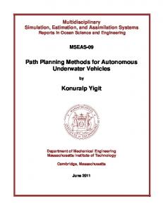
Figure 1: Simplified single-baseline Michelson interferometer a more thorough description of this background material.
2.1
Optical Interferometry
Long-baseline optical interferometry has been identified by NASA as a critical technology for the next generation of ground- and space-based telescopes. The basic idea is that light from multiple apertures can be interfered, providing the equivalent resolution of a much larger telescope. In order to eliminate the image-polluting effects of the Earth’s atmosphere, which reduce the effectiveness of groundbased telescopes, NASA is designing a series of spacebased telescopes to be launched in the next decade or so. These space observatories, including the StarLight interferometer, SIM, and the Terrestrial Planet Finder, are part of NASA’s Origins program. Figure 1 shows a simplified diagram representing a single-baseline optical Michelson stellar interferometer. Two physically separated telescopes (siderostats) collect starlight, and via a series of mirrors, bring the light to a beam combiner. Based on the interference pattern from the combined beams, a measurement of the external delay can be obtained, providing information on the angular position (a) of the observed star. In this section, the mechanisms used to measure external delay are discussed, with the goal of introducing the behavior and interactions of the components modeled in the RAI system. Prior to acquiring any science data, the instrument’s steerable optics must be pointed toward the target star. The accurate pointing of the instrument is enabled by the star tracker component, which encompasses the closed-loop system involving a siderostat (for low-bandwidth, coarse pointing control), at least one fast-steering mirror (for high-bandwidth,
fine pointing control) and one detector. There is a star tracker associated with each of the two optical paths in the interferometer system. Once the two individual science light paths have been established, light from the two collectors is combined at the beam combiner, typically with a half-silvered mirror, through reflection of one beam and transmission of the other. The combined beam is then focused onto a detector, which senses either a bright fringe (constructive interference) or a dark fringe (destructive interference), depending on the total optical path difference (OPD) between the two light paths (or ”arms”). A bright fringe is seen on the detector when the OPD is an integral number of wavelengths. Furthermore, for the usual case of white light, a peak in the fringe intensity is seen when the OPD is exactly zero. As OPD increases, the interference pattern becomes incoherent, and the detector records the mean intensity of the two beams. To achieve zero OPD, the instrument must introduce an internal delay in one of the two light paths, usually by adjusting the position of a movable delay line. The delay line is a multi-staged device consisting of a movable trolley (coarse stage), a voice-coil (intermediate stage), and piezoceramic actuator (fine stage). When the delay line position is set such that the peak intensity is detected, the fringe visibility amplitude can be read off the detector. Fringe visibility phase, which is necessary to obtain precise astrometric measurements, is extracted by dithering the path delay (using a dither input to the piezo stage on the delay line). The fringe tracker component, consisting of the closed-loop system involving the delay line and the science detector, is entrusted with keeping the central peak fringe ”locked” on the detector during observations. The measurement of the internal delay introduced in the delay line is done with an internal metrology system, consisting of a laser source which is split into two different beams, one for each arm of the interferometer. These two beams travel down the same two paths as the science light beams, from the beam combiner to the outer-most siderostats and back. A laser counter sensor is used to monitor the phase of the laser light fringes seen in the recombined metrology beam, providing an ongoing measure of the relative pathlength difference between the two arms. The discussion of the design and operation of an optical interferometer as presented in this subsection has been significantly simplified. A more thorough description of the instrument can be found in [5]. The corresponding operational details for a separatedspacecraft interferometer, such as the StarLight mis-
Internal Metrology Component Model Mode constraint: (not (counter_delta = out))
Locked
No mode constraints “likely”
homeset cmd “likely” reached homeset cmd Reset
Unlocked homeset cmd
Mode constraint: (not (counter_delta = out))
Figure 2: Transition system model for the Internal Metrology component sion, are provided in [6].
2.2
Remote Agent
The Remote Agent is a set of software allowing sophisticated monitoring and control for complex process control problems. Flight-validated as an experiment on the DS1 spacecraft [2], it has been repackaged as the foundation for process control in optical interferometry applications. Remote Agent for Interferometry consists of two of the original RA software elements, Livingstone and EXEC. Each of these elements will now be discussed in further detail. 2.2.1
Livingstone
Livingstone is a model-based monitoring, diagnosis and reconfiguration engine that performs significant deduction in the sense/response loop [7]. It uses common-sense qualitative models of spacecraft components and subsystems, expressed in a transition system formulation. The model dynamics are captured in concurrent automata, as shown in Figure 2 for the simple ”Internal Metrology” component. The states of each component automaton correspond to modes, with behaviors described by associated constraints. Transitions between modes can be either probabilistic or deterministic. System models are built compositionally by connecting the transition system models of the different components. In the Internal Metrology component example, the locked and reset modes are ”nominal” modes, and the unlocked mode is a ”fault” mode. Mode constraints are expressed in terms of variables over finite domains, e.g.: counter delta ∈ { hold, track, slew, out } Livingstone models compile down to propositional
Model
Controller
Goals
• s’(t) mode identification
mode reconfiguration
c(t)
o(t) s (t)
gg
•
ff
Plant
Figure 3: Control diagram showing Livingstone interface to a system (plant) • logic clauses, e.g.: (mode = locked) ⇒ (¬(counter delta = out)) (mode = locked) ∧ (dl cmd in = homeset) ⇒ (next(mode = reset))
•
It should be noted that only transitions to nominal modes are modeled deterministically within the clauses. Fault modes are associated with probability values (e.g. ”likely”, in the example from Figure 2 corresponds to a probability value of 1%), which are used during the diagnosis procedure. As shown in Figure 3, Livingstone is essentially a discrete model-based controller. Its sensing component (Mode Identification) takes as inputs observations from the plant. Based on these observations and its internal model of the system, it monitors the state of the system. As soon as a discrepancy between predicted and observed state is detected, it reasons through the propositional models to determine the most likely current state of the system. In the event of a failure, Livingstone’s commanding component (Mode Reconfiguration) can suggest a recovery action to take in order to achieve a desired goal configuration. 2.2.2
EXEC
EXEC is a robust, event-driven, goal-oriented and multi-threaded plan execution system. It is written in a rich procedural language, Execution Support Language (ESL), which is an extension to multithreaded Common Lisp. ESL provides the following features, allowing the encoding of execution knowledge into embedded autonomous agents [8]: • Contingency Handling - ESL provides constructs for signaling that failures have occurred and for specifying recovery procedures. • Timekeeping - ESL is designed to integrate seamlessly with external timekeeping sources,
providing capabilities for scheduling and timeout specification. Goal Achievement - ESL provides special syntax for decoupling achievement conditions and the methods of achieving those conditions. These goal achievement capabilities are similar to those provided by the RAPs executive [9]. Task Management - ESL supports multiple concurrent tasks, by leveraging Common Lisp’s multi-threading features. Task synchronization is provided by data objects called ’events’. A task can be made to wait for an event, causing it to block until another task signals that event. Logical Database - A logical database is provided as a modular functionality in ESL. The database can be used by an executive to store the monitored state variables of the system. Property Locks - ESL provides a mechanism for controlling inter-task conflicts (e.g. one task thread trying to turn on a device while a concurrent task requires it to be off). Property locks are used to coordinate tasks so they do not try to achieve different values for a single property at the same time.
Using ESL constructs corresponding to the above features, EXEC code can be structured so as to provide plan running and sequencing capabilities for the RA [10]. Since the RAI architecture does not currently include a planner/scheduler component, the discussion in this paper will refer to EXEC’s sequencing capabilities, rather than plan running. EXEC’s ability to express time-driven, event-driven, and context-sensitive relationships between activities provides a rich framework for robust sequencing.
3
RAI/RTC Architecture
As illustrated in the system architecture diagram (Figure 4), the Remote Agent and Real-Time Control software can run on separate processors. In the ground testbed environment, the Unix station hosting RA communicates with the PowerPC board running the VxWorks-based RTC, via a CORBA (Common Object Request Broker Architecture) interface. Commands flow from the EXEC element of the RA to the RTC, while telemetry streams from RTC are received by the RA monitor processes, and converted to the qualitative information used by Livingstone. The monitor values can be sent to Livingstone directly, or they can be ”disguised” as commands (called ”pseudo-commands”) if the monitor values need to be able to trigger nominal state changes. These translations to pseudo-commands are neces-
CORBA MESSAGES CLASH MESSAGES
REMOTE AGENT
offline Commands
RTC
EXEC
ping
ACE -TAO ORB
Telemetry Data
Telemetry Server
idle− cmd
off Commands
State updates
Recovery Requests
unknown
reached− homeset− cmd
back− cmd
reached− back− cmd
homing
backing front− cmd
Monitor Values ALLEGRO ORBLINK CLASH IPC
home
back
fronting
reached− front− cmd
slewing
reached− track− cmd
track− cmd
ACE -TAO ORB
Monitors
homeset− cmd
Recoveries
Livingstone Pseudo Commands
idle
front
track
Telemetry Data
Figure 4: RAI and RTC system architecture sary, because direct monitor values (”observables”) can only be used to trigger failure transitions. Interfacing between EXEC and Livingstone is done through CLASH, a socket-based inter-process communication system. The interface allows for information exchange in the form of commands, state updates, recovery strategy requests and recovery suggestions. Livingstone uses the telemetry information from RTC and knowledge of the EXEC-issued commands to monitor the state of the system, and informs EXEC of any inferred configuration changes. This interaction with MIR provides a level of abstraction to the EXEC, allowing it to reason at the level of system states. If a transition to a failure state is diagnosed, EXEC uses Livingstone’s mode reconfiguration capability to come up with a recovery action, which it can then execute by issuing the appropriate commands to RTC.
4
Livingstone Modeling
This section of the paper provides an overview of the various interferometer component models built for Livingstone, with the goal of conveying the complexity of their behavior and interactions. The models discussed here are those required to establish linear metrology and fringe tracking for a single interferometer baseline of the SIM Test Bed 3 (STB-3) at JPL. The components modeled for this task are: delay line, front and back limit switch sensors, path dither, laser counter, internal metrology and fringe tracker. Space limitations preclude a full description of each assembled component model. However, a brief overview of each model follows, highlighting the inputs, outputs and modes. Limit Switch Sensor - The limit switch sensors for the delay line are modeled as distinct components. A common model for sensors is used, allowing instantiation of limit switches at the front and back of the
Figure 5: Delay Line model (not all possible transitions are shown) trolley track. These sensors indicate when the trolley has reached the front or back of its travel. This type of component takes no input, and outputs an on-off signal, as well as a health state. The model for the limit switch is very simple, consisting of one nominal mode (in which the signal output is ”on” when the DL is on the sensor, and ”off” otherwise), and one broken mode (capturing any off-nominal behavior). It should be noted that there is currently no measure of the health-state of a sensor on STB-3. This lack of observability precludes transitions into broken mode. Delay Line - The delay line (DL) provides coarse and fine path length control within an arm of an interferometer baseline. However, control of the fine stages is captured within the fringe tracker and path dither models. As such, the DL model mainly captures the coarse action of the trolley stage. The DL component takes as inputs signals from the front and back limit switch sensors, the home sensor signal (which turns on when the trolley passes over the fixed home sensor), the laser counter delta (rate of change between successive laser counter readings), and a delay line command. It outputs a DL servostate telemetry item. Figure 5 illustrates the model for the DL, including the modes and some of the commanded transitions. Here, as for all the following components, the mode constraints are omitted from the figure for the sake of clarity. It should also be noted that all transition label commands beginning with ”reached” correspond to pseudo-commands, as described in Section 3 (e.g. when the DL trolley finally settles onto the home sensor after being issued the ’homeset’ command, the ’reached-homeset’ pseudo-command is fired). Path Dither - The path dither (PD) component is modeled as distinct from the DL, though it represents dithering of its piezo stage. Once the form of the dither signal has been calibrated, the PD enables
off
on−cmd
offline
uncalibrated
idle− cmd
idle− cmd
idle
calibrate− cmd
off−cmd
off−cmd
off−cmd
off
search
unknown
reached− calibrated− cmd
reached− search− cmd
idle− cmd
calibrating
calibrate− cmd
track
track− cmd
ping
calibrated idle− cmd
idle− cmd reached− lock− cmd
lock
reached− semi−lock− cmd
semi− lock
reached− search− cmd reached− search− cmd
Figure 6: Path Dither model "any DL motion cmd"
zeroed
"any DL motion cmd"
not−zeroed zero− cmd
reached− homeset− cmd
implicitly− zeroed
unknown zero− cmd
reached− homeset− cmd
Figure 7: Laser Counter model an integrated measurement over a full wavelength of the science light. The PD component takes as input a PD command, and outputs a health state. There is currently no telemetry for PD health on STB-3, so it is assumed to behave nominally. Figure 6 illustrates the model for the PD. Laser Counter - The laser counter (LC) component is used to measure the relative delay between two arms of an interferometer baseline. It counts the number of metrology laser beam wavefronts seen on its detector, starting from a ”zero” reference point. The LC takes as inputs a laser counter command and a delay line command (the LC gets implicitly-zeroed when the ’reached-homeset’ pseudo-command is issued). The LC outputs the counter value and the counter delta (sudden jumps in the counter delta value signal that metrology lock has been broken). Figure 7 describes the LC model. Internal Metrology - The internal metrology (IM) state is modeled as a distinct component, separate from the LC. The IM system takes as inputs the LC counter delta and DL command. The model is simple, as shown in Figure 2. The IM is reset when the ’homeset’ DL command is issued, and becomes locked when the ’reached-homeset’ pseudo-command is fired. IM becomes unlocked if a jump in counter delta is detected, as a result of the metrology laser beam being broken.
Figure 8: Fringe Tracker model (not all possible transitions are shown) Fringe Tracker - The fringe tracker (FT) component encompasses the closed-loop system involving the DL and the science camera. As mentioned above, the fine stages of the DL are controlled by the FT. It should be noted that correct operation of the FT component depends on the activation and successful calibration of the PD component. The FT component takes as input the FT command, and it outputs a FT servo-state telemetry item. Figure 8 describes the FT model. The track, search and semi-lock are transient intermediate states passed through on the way to the lock mode. Lock is achieved once the RTC indicates via telemetry that the closed-loop control of the FT is successfully tracking the science fringe. Other models, corresponding to components of the starlight pointing subsystem (including the star tracker ) and components of the angular metrology subsystem, have been developed, but they will not be discussed here. The angular metrology subsystem is required to establish and maintain the IM laser beam link between the individual free-flying spacecraft in a separated spacecraft interferometer.
5
EXEC Constructs
In order to construct a robust sequencing engine for an interferometer system, many of the features provided by ESL are leveraged. The EXEC code must incorporate constructs for exception handling, timeouts, concurrent thread spawning, event synchronization, goal achievement, and resource management. In building up the EXEC sequencing constructs, a hierarchical object-based approach was adopted, to maximize modularity of the procedural code. The following architectural principles were established:
1. Use a single Application Programming Interface (API) for low-level commanding of all devices 2. Provide a common API for issuing state achievement requests to all devices 3. Bound all operations and commands by welldefined timeouts, to allow exception handling in case of communication or hardware failures 4. Allow context-sensitive recovery actions, for all anticipated failure scenarios 5. Define a common structure for similar EXEC objects associated with different devices The set of EXEC constructs is divided into general and component-specific constructs. The general constructs include code for issuing commands over the CLASH and CORBA links, state database initialization, and state transition event definition. The component-specific constructs include timeout definitions, state achievement functions, and recovery procedures. By layering and combining the component-specific constructs, it then becomes straightforward to define ”composite” or subsystemlevel constructs, e.g. constructs enabling achievement and maintenance of fringe tracking, which requires establishing IM lock (by homesetting the delay line and implicitly zeroing the laser counter), establishing delay line tracking, activating and calibrating the path dither, and finally, closing the fringe tracker servo loop.
6
Demonstrated Capabilities
Using the Livingstone models presented in Section 4 and the EXEC code described in Section 5, autonomous control of a nominal operation scenario was demonstrated on the STB-3 testbed. A variety of features were successfully implemented, ranging from basic interactive commanding of testbed components to more complex constructs for state achievement and maintenance, with autonomous recoveries. The demonstrated scenario consisted of bringing the interferometer instrument online from an idle state, achieving internal metrology lock, and acquiring the science fringe. In particular, the steps of the nominal procedure were as follows: • Initial state: DL and FT both in idle mode, LC not-zeroed, PD off, IM unlocked ; • Send DL to front of track; • Calibrate PD; • Homeset DL (which zeroes LC and locks IM); • Slew DL to estimated fringe position; • With DL tracking, perform fringe search;
• When science fringe is detected, FT locks onto fringe. Robustness of the system was tested by artificially introducing a fault into the system while fringe tracking: in this case, causing the internal metrology to lose lock (by introducing a transient interruption in the metrology beam). The RAI system correctly diagnosed the fault and initiated a recovery sequence, resulting in re-acquisition of internal metrology lock, followed by re-acquisition of fringe tracking.
7
Lessons Learned
The principal lessons learned during development, integration and testing of the RAI modules were: Interface complexity - Dealing with the complex interfaces between various modules in the system (Livingstone, EXEC, and RTC) proved to be one of the most significant challenges encountered. This highlights the importance of establishing clear interface specifications for future integration efforts. Scoping of the models - As currently modeled, there are Livingstone models of ”primitive” components, like the limit switch sensors, more complex components like the delay line and fringe tracker (which encompasses some delay line functionality coupled with a science camera), and at an even more abstract level, the internal metrology component (which is not a physical component at all, but rather an abstraction for the lock state of the delay line/laser counter subsystem). Although the current model captures the required functionality, scoping the models differently might prove more effective. Flexibility of the Interface Definition Language (IDL) - For the purposes of this task, the IDL established by the RTC system was assumed fixed. The RA models proved flexible enough to accommodate the fixed command and object vocabulary, at least for the purposes of this preliminary demonstration. However, in order to optimize the effectiveness of the system for future development, feedback from the RA modeling process should be used in defining/refining the IDL. Parallel and mutually influencing development of the RA process control code and the RTC software can only improve the overall performance of the system. System observability - One frustration that was frequently encountered was the absence or inaccessibility of a desired telemetry item (e.g. limit switch health, path dither calibration status). This challenge points again to the potential benefit of using the RA modeling process to help define the RTC
telemetry structure for optimal system performance. Multi-step recoveries - The MIR implementation used for this task only provides single-step recovery actions. In order to accomplish multiple-step recovery procedures such as restoring internal metrology lock, knowledge of the recovery sequences must be encoded within EXEC. It would be better to allow MIR to reason through multiple steps of model interactions. This capability has been developed in the Burton reactive planner [3]. Incorporation of Burton into RAI is targeted as future work. Commanded nominal transitions - Another limitation of the MIR implementation used in this task is that its underlying transition system model requires that transitions between nominal modes be conditioned only on commands. A workaround was implemented within the RAI monitors, effectively allowing transitions to be conditioned on observables (in the form of pseudo-commands), but this is not an elegant or particularly intuitive solution to the problem. A more general transition system model, allowing transitions between nominal modes conditioned on any variable, including observable and state variables, would lead to a more capable MIR module.
8
Future Work
The following tasks are identified for future work: - Streamlining of the RAI/RTC interface code and file structure, including replacement of CLASH interfaces with CORBA. - Improvement of model fidelity. Each component has been modeled such that its operational states are captured as modes. Future work might include independent consideration of operational states, health states, power states, and calibration states. A component ”mode” would then consist of an assignment to each of these states. Also, the interferometer system performance might be improved by accurately modeling the ”quality” of the FT lock, which might degrade over the tracking process, and might require returning to the search mode. - Investigation of issues arising from concurrent commanding of multiple interferometer baselines, as will be the case for SIM. - RAI deployment on other interferometer testbeds. - Integration of the Burton reactive planner. - Integration of an updated C++ MIR system [11]. - Investigation of an alternative to EXEC, possibly including an integrated model-based execution framework [12], or an integrated planning/execution system [13], both currently under development.
9
Acknowledgments
This paper describes work performed at the Jet Propulsion Laboratory, California Institute of Technology, under contract from the National Aeronautics and Space Administration.
References [1] Bernard, D.E. et al., ”Design of the Remote Agent Experiment for Spacecraft Autonomy”, Proc. of the IEEE Aerospace Conference, 1999. [2] Nayak, P.P. et al., ”Validating the DS1 Remote Agent Experiment”, Proc. of iSAIRAS1999, 1999. [3] Williams, B.C. and Nayak, P.P., ”A Reactive Planner for a Model-Based Executive”, Proc. of IJCAI-97, 1997. [4] Chien, S. et al., ”An Autonomous Sciencecraft Constellation”, Proc. of iSAIRAS-2001, 2001. [5] Space Interferometry Mission - Taking the Measure of the Universe, Danner, R. and Unwin, S., editors, NASA/JPL publication, California Institute of Technology, Pasadena, CA, March 1999. [6] Lay, O., ST3 Instrument Requirements and Design Document, version 1.0, JPL Internal Document ST3-3-5101, January 2000. [7] Williams, B.C. and Nayak, P.P., ”A ModelBased Approach to Reactive Self-Configuring Systems”, Proc. of AAAI-96, 1996. [8] Gat, E., ”ESL: A Language for Supporting Robust Plan Execution in Embedded Autonomous Agents”, Proc. of the AAAI Fall Symposium on Plan Execution, 1996. [9] Firby, R.J., Adaptive Execution in Dynamic Domains, Ph.D. Thesis, Yale University Department of Computer Science, 1989. [10] Pell, B. et al., ”The Remote Agent Executive: Capabilities to Support Integrated Robotic Agents”, Proc. of the AAAI Spring Symposium on Integrated Robotic Architectures, 1998. [11] Kurien, J. and Nayak, P.P., ”Back to the Future with Consistency-based Trajectory Tracking”, Proc. of AAAI-2000, 2000. [12] Ingham, M., Ragno, R. and Williams, B., ”A Reactive Model-based Programming Language for Robotic Space Explorers”, Proc. of iSAIRAS-2001, 2001. [13] Muscettola, N., et al.,”A Unified Approach to Model-Based Planning and Execution”, Proc. of the 6th International Conference on Intelligent Autonomous Systems (IAS-6), 2000.